EP0609640A2 - Schalterkalibriermechanismus - Google Patents
Schalterkalibriermechanismus Download PDFInfo
- Publication number
- EP0609640A2 EP0609640A2 EP93630102A EP93630102A EP0609640A2 EP 0609640 A2 EP0609640 A2 EP 0609640A2 EP 93630102 A EP93630102 A EP 93630102A EP 93630102 A EP93630102 A EP 93630102A EP 0609640 A2 EP0609640 A2 EP 0609640A2
- Authority
- EP
- European Patent Office
- Prior art keywords
- switch
- bushing
- cam
- cam surface
- calibrating
- Prior art date
- Legal status (The legal status is an assumption and is not a legal conclusion. Google has not performed a legal analysis and makes no representation as to the accuracy of the status listed.)
- Granted
Links
Images


Classifications
-
- H—ELECTRICITY
- H01—ELECTRIC ELEMENTS
- H01H—ELECTRIC SWITCHES; RELAYS; SELECTORS; EMERGENCY PROTECTIVE DEVICES
- H01H37/00—Thermally-actuated switches
- H01H37/02—Details
- H01H37/12—Means for adjustment of "on" or "off" operating temperature
-
- H—ELECTRICITY
- H01—ELECTRIC ELEMENTS
- H01H—ELECTRIC SWITCHES; RELAYS; SELECTORS; EMERGENCY PROTECTIVE DEVICES
- H01H37/00—Thermally-actuated switches
- H01H37/02—Details
- H01H37/12—Means for adjustment of "on" or "off" operating temperature
- H01H37/24—Means for adjustment of "on" or "off" operating temperature by adjustment of position of the movable contact on its driving member
-
- H—ELECTRICITY
- H01—ELECTRIC ELEMENTS
- H01H—ELECTRIC SWITCHES; RELAYS; SELECTORS; EMERGENCY PROTECTIVE DEVICES
- H01H37/00—Thermally-actuated switches
- H01H37/02—Details
- H01H37/12—Means for adjustment of "on" or "off" operating temperature
- H01H37/30—Means for adjustment of "on" or "off" operating temperature by varying the position of the contact unit in relation to switch base or casing
-
- Y—GENERAL TAGGING OF NEW TECHNOLOGICAL DEVELOPMENTS; GENERAL TAGGING OF CROSS-SECTIONAL TECHNOLOGIES SPANNING OVER SEVERAL SECTIONS OF THE IPC; TECHNICAL SUBJECTS COVERED BY FORMER USPC CROSS-REFERENCE ART COLLECTIONS [XRACs] AND DIGESTS
- Y10—TECHNICAL SUBJECTS COVERED BY FORMER USPC
- Y10T—TECHNICAL SUBJECTS COVERED BY FORMER US CLASSIFICATION
- Y10T74/00—Machine element or mechanism
- Y10T74/21—Elements
- Y10T74/2101—Cams
-
- Y—GENERAL TAGGING OF NEW TECHNOLOGICAL DEVELOPMENTS; GENERAL TAGGING OF CROSS-SECTIONAL TECHNOLOGIES SPANNING OVER SEVERAL SECTIONS OF THE IPC; TECHNICAL SUBJECTS COVERED BY FORMER USPC CROSS-REFERENCE ART COLLECTIONS [XRACs] AND DIGESTS
- Y10—TECHNICAL SUBJECTS COVERED BY FORMER USPC
- Y10T—TECHNICAL SUBJECTS COVERED BY FORMER US CLASSIFICATION
- Y10T74/00—Machine element or mechanism
- Y10T74/21—Elements
- Y10T74/2101—Cams
- Y10T74/2107—Follower
Definitions
- This application relates to the art of switches and, more particularly, to calibration mechanisms for switches.
- the invention is particularly applicable for use in a temperature responsive switch and will be described with specific reference thereto. However, it will be appreciated that the invention has broader aspects and can he used in any switch requiring calibration.
- a calibration mechanism for a switch having a movable calibrating member to vary the switch operating point.
- the calibration mechanism includes a rotatable cam member that is rotatable about a longitudinal axis and also moves axially along such axis responsive to rotation thereof.
- a cam surface on the rotatable cam member cooperates with the switch calibrating member for adjustably moving same responsive to axial movement of the rotatable cam member.
- the cam surface on the cam member lies on the surface of a cone that has a cone axis coincidental with the rotational longitudinal axis of the cam member.
- the rotatable cam member has an externally threaded portion that is threadably received in a threaded bushing.
- the bushing has an external flat surface engaging an abutment for preventing rotation of the bushing and this provides enhanced stability by preventing unintentional rotation of the bushing and cam member.
- the bushing preferably extends through a hole in a support arm for the calibrating member and is secured to a switch case.
- the external flat surface on the bushing for preventing rotation thereof is preferably provided by a polygonal bushing portion located inside of the switch case.
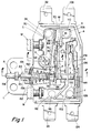
- Figure 1 shows a switch case A of dielectric material having a limit switch and a hot light warning switch mounted therein.
- the limit switch includes normally closed fixed and movable contacts 10, 12 that are opened when an excessive temperature condition occurs and this prevents damage to a cooktop due to overheating.
- the limit switch can be calibrated to open at a temperature between 545°C - 750°C.
- the hot light warning switch has normally open, fixed and movable contacts 16, 18 that are closed when a cooktop reaches a predetermined temperature.
- the hot light warning switch can be calibrated to close when the sensed temperature of the cooktop is between 75°C - 140°C.
- Temperature sensing means B for sensing the temperature of the cooktop and operating the switches includes a metal rod 20 extending through a glass tube 22.
- Metal rod 20 has a much larger coefficient of thermal expansion than glass tube 22, and rod 20 moves to the right in Figure 1 as sensing means B is heated.
- the temperature of sensing means B rises until rod 20 expands far enough to operate the hot light warning switch and close contacts 16, 18.
- rod 20 will expand far enough to operate the limit switch and open contacts 10, 12 to de-energize the heating element.
- the hot light warning switch includes a support C having a base portion 30 attached to switch case A and to a terminal 32 by a rivet 34.
- Support C has an upright portion 36 perpendicular to base portion 30.
- An elongated slot 38 in upright portion 36 adjacent to base portion 30 forms an elongated bendable arm 40 that terminates in an integral perpendicular finger 42 having a generally V-shaped groove 44 therein.
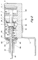
- An internally threaded bushing D has a cylindrical portion 46 extending through suitable holes in switch case A and base portion 30 of support C.
- a washer 48 is positioned over the free end portion of bushing cylindrical portion 46 outside of switch case A and the terminal end portion of bushing cylindrical portion 46 is turned over as indicated at 50 in Figure 3.
- Bushing D has an enlarged polygonal portion 52 located on the opposite side of support base portion 30 from switch case A.
- Bushing polygonal portion 52 has a plurality of flats thereon and one such flat 54 defines engaging means that is closely received against an abutment provided by upright support portion 36 below slot 38 to prevent rotational movement of bushing D.
- a rotatable cam member E has a threaded shank 56 that is threadably received in bushing D.
- Cam member E has a cam surface 58 that lies on the surface of a cone for cooperation with a boss 60 that is deformed outwardly on arm 40 of support C.
- the end portion of cam member E has a recess 62 shaped for receiving a driving tool for selectively rotating cam member E.
- Rotational movement of cam member E also moves same axially along its longitudinal axis 64, and the cooperative engagement between cam surface 58 and the boss 60 moves arm 40 toward or away from axis 64 depending upon the direction of rotation of cam member E.
- the movable arm 40 defines a movable calibrating member that is adjustably moved by rotation of cam member E. Movement of the calibrating member varies the location of groove 44 in finger 42 for adjusting the operating point of the hot light switch. After cam member E has been adjusted, thread sealant can be positioned within the open end of bushing D to prevent rotation of the cam member. Cam member E is effective to adjustably move the calibrating member defined by arm 40 during rotation of the cam member through a plurality of complete 360° rotations in the same direction.
- the tapered cam surface defined by frusto-conical portion 58 increases in diameter in a direction away from its threaded shank 56.
- the inclination of the tapered surface defined by frusto-conical portion 58 is such that it forms an included angle with longitudinal axis 64 between about 15° - 25°.
- the length of tapered surface 58 along longitudinal axis 64 is at least 0.375 inch.
- the degree of adjustment made by each rotation of cam member E will depend upon the pitch of the threads. In one arrangement, each complete 360° rotation of cam member E moves the calibrating member defined by arm 40 about 0.005 - 0.007 inch toward or away from longitudinal axis 64. This makes it possible to achieve a very fine adjustment of the operating point for the hot light warning switch.
- a carrier F for the movable contact of the hot light warning switch has one end portion secured to upright portion 36 of support C by rivet 70. Integral flanges 72 are provided over a major portion of the length of carrier F to impart stiffness thereto. An enlarged aperture 74 is provided in carrier F for receiving a leaf spring 76 on a snap blade G that carries movable contact 18.
- the free end portion of carrier F has a hole 77 therethrough with opposite flat sides, 78, 80.
- a pair of pimples 82 are deformed outwardly from the free end portion of carrier F on opposite sides of hole 77.
- a bumper H has an enlarged head 84 and an elongated pin portion 86 that extends through hole 77 in carrier F. Opposite flat surfaces 88, 90 on pin portion 86 of bumper H cooperate with flats 78, 80 of hole 77 to prevent rotation of bumper H. This maintains more accurate adjustment of the operating points of the switches.
- the flat radial surface 92 at the intersection of bumper head 84 with pin portion 86 defines a shoulder that engages pimples 82 on carrier F.
- End portion 94 of snap blade G is welded to the free end portion of carrier F.
- a hole 96 in snap blade end portion 94 is aligned with carrier hole 77 for freely receiving pin portion 86 on bumper H.
- Integral spring member 76 on snap blade G is under bending stress with its terminal end 98 received in groove 44 of finger 82 on the calibrating member defined by arm 40 on support C.
- a tab 102 bent outwardly from carrier F provides a stop engageable by snap blade G on the opposite side thereof from movable contact 18 in the open contact position of the hot light warning switch. Movement of the welded together end portions of carrier F and snap blade G by bumper H relative to groove 44 and terminal end 98 of spring portion 76 causes snap movement of blade G to open and close contacts 16, 18. Adjustment of cam member E moves groove 44 and terminal end 98 of spring portion 76 relative to the welded together end portions of carrier F and snap blade G to adjust the point at which snap action occurs.
- Fixed contact 16 of the hot light warning switch is on a support R having a base portion 106 attached to switch case A and to a terminal 108 by a rivet 110.
- a limit switch support I has a base portion 112 secured to switch case A and to a terminal 114 by rivet 116.
- An upright portion 118 of limit switch support I has fixed contact 10 thereon and has a hole 120 aligned with holes 96, 77 for freely receiving pin portion 86 of bumper H.
- Limit switch support J has a base portion 122 secured to switch case A and to a terminal 124 by rivet 126. Upright portion 128 of support J has end portion 130 of snap blade K attached thereto by a rivet 132. A finger 134 on upright portion 128 of support J has a generally V-shaped groove 136 therein receiving terminal end 140 on leaf spring 142 integral with snap blade K that carries movable contact 12. An integral lateral boss 144 on snap blade K is engaged by the terminal end of bumper H to move snap blade K relative to groove 134 and spring member terminal end 140 to effect snap movement of snap blade K between contacts open and closed positions.
- a switch mounting bracket L is attached to one side of switch case A by nut and bolt assemblies M, N.
- a spherically curved boss 150 on bracket L has a similarly curved washer 152 received thereover and a similarly curved bearing member 154 has a cylindrical recess 156 receiving an end portion of glass tube 22.
- a retaining member 158 attached to the free end portion of metal rod 20 traps glass tube 22 on rod 20.
- a coil spring 160 acts between a flange 162 on an eyelet P and the inner side of spherically curved boss 150 to urge rod 20 to the right in Figure 1.
- the end of rod 20 engages enlarged head 84 on bumper H. When rod 20 expands, it moves to the right along with bumper H to close contacts 16, 18 of the hot light warning switch. In the event of an over-temperature condition, rod 20 will expand far enough to the right for moving bumper H a sufficient distance to open limit switch contacts 10, 12.
- switch mounting bracket L in which spherically curved boss 150 is formed has an upper end 170 that is overlapped by switch cover 172.
- Cover 172 has a suitable hole therethrough for receiving a screw that threads into a tapped hole 174 in switch case A. This overlapping arrangement of the cover with the mounting bracket helps to seal the interior of the switch case against dirt.
Landscapes
- Thermally Actuated Switches (AREA)
- Rotary Switch, Piano Key Switch, And Lever Switch (AREA)
- Push-Button Switches (AREA)
Applications Claiming Priority (2)
| Application Number | Priority Date | Filing Date | Title |
|---|---|---|---|
| US11532 | 1993-02-01 | ||
| US08/011,532 US5297446A (en) | 1993-02-01 | 1993-02-01 | Switch calibration mechanism |
Publications (3)
| Publication Number | Publication Date |
|---|---|
| EP0609640A2 true EP0609640A2 (de) | 1994-08-10 |
| EP0609640A3 EP0609640A3 (de) | 1995-05-17 |
| EP0609640B1 EP0609640B1 (de) | 1997-07-16 |
Family
ID=21750799
Family Applications (1)
| Application Number | Title | Priority Date | Filing Date |
|---|---|---|---|
| EP93630102A Expired - Lifetime EP0609640B1 (de) | 1993-02-01 | 1993-12-09 | Schalter mit Kalibriermechanismus |
Country Status (5)
| Country | Link |
|---|---|
| US (1) | US5297446A (de) |
| EP (1) | EP0609640B1 (de) |
| JP (1) | JPH06243766A (de) |
| CA (1) | CA2113136A1 (de) |
| DE (1) | DE69312256T2 (de) |
Families Citing this family (2)
| Publication number | Priority date | Publication date | Assignee | Title |
|---|---|---|---|---|
| US6272949B1 (en) * | 1998-12-23 | 2001-08-14 | Amsted Industries Incorporated | Air operated fifth wheel uncoupling apparatus |
| US12140398B2 (en) * | 2022-01-06 | 2024-11-12 | Copper John Corporation | Archery trigger adjuster and method for archery release devices |
Family Cites Families (12)
| Publication number | Priority date | Publication date | Assignee | Title |
|---|---|---|---|---|
| GB1094735A (en) * | 1966-01-18 | 1967-12-13 | Ass Elect Ind | Improvements in electric thermal switches |
| US3527117A (en) * | 1968-05-28 | 1970-09-08 | Pegasus Lab Inc | Structure for and method of tracing stylus deflection limiting |
| US3517913A (en) * | 1968-10-23 | 1970-06-30 | Walter J Van Rossem | Vibrating table construction |
| US3841626A (en) * | 1973-03-01 | 1974-10-15 | Miller Printing Machinery Co | Sheet feeding apparatus |
| US3915129A (en) * | 1974-09-18 | 1975-10-28 | Robert H Rust | Internal combustion engine |
| US4160225A (en) * | 1977-11-14 | 1979-07-03 | General Electric Company | Temperature responsive control device with improved hydraulic diaphragm |
| US4164097A (en) * | 1978-05-08 | 1979-08-14 | Walter Hernandez | Optical lens grinder device |
| US4388505A (en) * | 1981-02-09 | 1983-06-14 | Puritan-Bennett Corp. | Adjustable pressure-actuated switch |
| US4471859A (en) * | 1982-06-07 | 1984-09-18 | Eaton Corporation | Drum brake |
| US4448550A (en) * | 1982-07-14 | 1984-05-15 | The Torrington Company | Bearing |
| US4841792A (en) * | 1988-01-21 | 1989-06-27 | The United States Of America As Represented By The United States Department Of Energy | Variable loading roller |
| US5152188A (en) * | 1990-02-20 | 1992-10-06 | Beckman Instruments, Inc. | Floating reciprocating shaft |
-
1993
- 1993-02-01 US US08/011,532 patent/US5297446A/en not_active Expired - Fee Related
- 1993-12-09 DE DE69312256T patent/DE69312256T2/de not_active Expired - Fee Related
- 1993-12-09 EP EP93630102A patent/EP0609640B1/de not_active Expired - Lifetime
- 1993-12-28 JP JP5350611A patent/JPH06243766A/ja active Pending
-
1994
- 1994-01-10 CA CA002113136A patent/CA2113136A1/en not_active Abandoned
Also Published As
| Publication number | Publication date |
|---|---|
| DE69312256D1 (de) | 1997-08-21 |
| JPH06243766A (ja) | 1994-09-02 |
| DE69312256T2 (de) | 1997-10-30 |
| US5297446A (en) | 1994-03-29 |
| EP0609640A3 (de) | 1995-05-17 |
| CA2113136A1 (en) | 1994-08-02 |
| EP0609640B1 (de) | 1997-07-16 |
Similar Documents
| Publication | Publication Date | Title |
|---|---|---|
| US2265629A (en) | Coil spring connector | |
| JPH0561756B2 (de) | ||
| US2249837A (en) | Thermostat | |
| JPS63252376A (ja) | 温度制限器 | |
| US4695816A (en) | Thermal cut-out | |
| US5297446A (en) | Switch calibration mechanism | |
| JPS63141229A (ja) | 電気スイッチ装置 | |
| US3164701A (en) | Method of assembling thermostatic switches | |
| US4555688A (en) | Thermostat for cooking utensil | |
| US2768263A (en) | Switch mechanism | |
| US5627507A (en) | Temperature control device with a spring-biased stem and a switch spring of bridge-like configuration | |
| GB2156157A (en) | Dual temperature thermostat | |
| US2518595A (en) | Positive "off" thermostatic switch | |
| US4362916A (en) | Miniature precision snap action switch having operating lever providing large overtravel | |
| US4782318A (en) | Thermally responsive electric switch apparatus | |
| US5548266A (en) | Thermostat construction | |
| GB2293048A (en) | Snap-acting spring switch element | |
| CN112786494B (zh) | 热电偶固定装置、半导体工艺设备 | |
| DE68916025T2 (de) | Einstellbarer elektrischer Thermostat mit Temperaturkompensation. | |
| US4733026A (en) | Adjustable switch and actuator arm | |
| US5304004A (en) | Thermometer movement cap nut assembly | |
| US5173679A (en) | Thermostatically controlled switch | |
| US4301438A (en) | Adjustable force producing means for manually movable control levers in a space thermostat | |
| JPS6123617B2 (de) | ||
| GB2293049A (en) | Method for assembly of a condition-responsive electric switch |
Legal Events
| Date | Code | Title | Description |
|---|---|---|---|
| PUAI | Public reference made under article 153(3) epc to a published international application that has entered the european phase |
Free format text: ORIGINAL CODE: 0009012 |
|
| AK | Designated contracting states |
Kind code of ref document: A2 Designated state(s): DE GB IT |
|
| PUAL | Search report despatched |
Free format text: ORIGINAL CODE: 0009013 |
|
| AK | Designated contracting states |
Kind code of ref document: A3 Designated state(s): DE GB IT |
|
| 17P | Request for examination filed |
Effective date: 19950727 |
|
| 17Q | First examination report despatched |
Effective date: 19960625 |
|
| GRAG | Despatch of communication of intention to grant |
Free format text: ORIGINAL CODE: EPIDOS AGRA |
|
| GRAH | Despatch of communication of intention to grant a patent |
Free format text: ORIGINAL CODE: EPIDOS IGRA |
|
| GRAH | Despatch of communication of intention to grant a patent |
Free format text: ORIGINAL CODE: EPIDOS IGRA |
|
| GRAA | (expected) grant |
Free format text: ORIGINAL CODE: 0009210 |
|
| AK | Designated contracting states |
Kind code of ref document: B1 Designated state(s): DE GB IT |
|
| REF | Corresponds to: |
Ref document number: 69312256 Country of ref document: DE Date of ref document: 19970821 |
|
| ITF | It: translation for a ep patent filed | ||
| PG25 | Lapsed in a contracting state [announced via postgrant information from national office to epo] |
Ref country code: GB Free format text: LAPSE BECAUSE OF NON-PAYMENT OF DUE FEES Effective date: 19971209 |
|
| PLBE | No opposition filed within time limit |
Free format text: ORIGINAL CODE: 0009261 |
|
| STAA | Information on the status of an ep patent application or granted ep patent |
Free format text: STATUS: NO OPPOSITION FILED WITHIN TIME LIMIT |
|
| 26N | No opposition filed | ||
| GBPC | Gb: european patent ceased through non-payment of renewal fee |
Effective date: 19971209 |
|
| PG25 | Lapsed in a contracting state [announced via postgrant information from national office to epo] |
Ref country code: DE Free format text: LAPSE BECAUSE OF NON-PAYMENT OF DUE FEES Effective date: 19980901 |
|
| PG25 | Lapsed in a contracting state [announced via postgrant information from national office to epo] |
Ref country code: IT Free format text: LAPSE BECAUSE OF NON-PAYMENT OF DUE FEES Effective date: 20051209 |