EP0609867A2 - Procédé de fabrication d'une couche semi-conductrice cristallisée et procédé de fabrication d'un dispositif semi-conducteur l'utilisant - Google Patents
Procédé de fabrication d'une couche semi-conductrice cristallisée et procédé de fabrication d'un dispositif semi-conducteur l'utilisant Download PDFInfo
- Publication number
- EP0609867A2 EP0609867A2 EP94101571A EP94101571A EP0609867A2 EP 0609867 A2 EP0609867 A2 EP 0609867A2 EP 94101571 A EP94101571 A EP 94101571A EP 94101571 A EP94101571 A EP 94101571A EP 0609867 A2 EP0609867 A2 EP 0609867A2
- Authority
- EP
- European Patent Office
- Prior art keywords
- silicon film
- substrate
- forming
- plasma
- coating
- Prior art date
- Legal status (The legal status is an assumption and is not a legal conclusion. Google has not performed a legal analysis and makes no representation as to the accuracy of the status listed.)
- Ceased
Links
Images


Classifications
-
- H—ELECTRICITY
- H10—SEMICONDUCTOR DEVICES; ELECTRIC SOLID-STATE DEVICES NOT OTHERWISE PROVIDED FOR
- H10D—INORGANIC ELECTRIC SEMICONDUCTOR DEVICES
- H10D86/00—Integrated devices formed in or on insulating or conducting substrates, e.g. formed in silicon-on-insulator [SOI] substrates or on stainless steel or glass substrates
-
- H—ELECTRICITY
- H10—SEMICONDUCTOR DEVICES; ELECTRIC SOLID-STATE DEVICES NOT OTHERWISE PROVIDED FOR
- H10D—INORGANIC ELECTRIC SEMICONDUCTOR DEVICES
- H10D30/00—Field-effect transistors [FET]
- H10D30/01—Manufacture or treatment
- H10D30/021—Manufacture or treatment of FETs having insulated gates [IGFET]
- H10D30/031—Manufacture or treatment of FETs having insulated gates [IGFET] of thin-film transistors [TFT]
- H10D30/0312—Manufacture or treatment of FETs having insulated gates [IGFET] of thin-film transistors [TFT] characterised by the gate electrodes
- H10D30/0314—Manufacture or treatment of FETs having insulated gates [IGFET] of thin-film transistors [TFT] characterised by the gate electrodes of lateral top-gate TFTs comprising only a single gate
-
- H—ELECTRICITY
- H10—SEMICONDUCTOR DEVICES; ELECTRIC SOLID-STATE DEVICES NOT OTHERWISE PROVIDED FOR
- H10D—INORGANIC ELECTRIC SEMICONDUCTOR DEVICES
- H10D30/00—Field-effect transistors [FET]
- H10D30/01—Manufacture or treatment
- H10D30/021—Manufacture or treatment of FETs having insulated gates [IGFET]
- H10D30/031—Manufacture or treatment of FETs having insulated gates [IGFET] of thin-film transistors [TFT]
- H10D30/0321—Manufacture or treatment of FETs having insulated gates [IGFET] of thin-film transistors [TFT] comprising silicon, e.g. amorphous silicon or polysilicon
-
- H—ELECTRICITY
- H10—SEMICONDUCTOR DEVICES; ELECTRIC SOLID-STATE DEVICES NOT OTHERWISE PROVIDED FOR
- H10D—INORGANIC ELECTRIC SEMICONDUCTOR DEVICES
- H10D30/00—Field-effect transistors [FET]
- H10D30/60—Insulated-gate field-effect transistors [IGFET]
- H10D30/67—Thin-film transistors [TFT]
- H10D30/674—Thin-film transistors [TFT] characterised by the active materials
- H10D30/6741—Group IV materials, e.g. germanium or silicon carbide
- H10D30/6743—Silicon
- H10D30/6744—Monocrystalline silicon
-
- H—ELECTRICITY
- H10—SEMICONDUCTOR DEVICES; ELECTRIC SOLID-STATE DEVICES NOT OTHERWISE PROVIDED FOR
- H10D—INORGANIC ELECTRIC SEMICONDUCTOR DEVICES
- H10D86/00—Integrated devices formed in or on insulating or conducting substrates, e.g. formed in silicon-on-insulator [SOI] substrates or on stainless steel or glass substrates
- H10D86/01—Manufacture or treatment
- H10D86/021—Manufacture or treatment of multiple TFTs
- H10D86/0221—Manufacture or treatment of multiple TFTs comprising manufacture, treatment or patterning of TFT semiconductor bodies
- H10D86/0223—Manufacture or treatment of multiple TFTs comprising manufacture, treatment or patterning of TFT semiconductor bodies comprising crystallisation of amorphous, microcrystalline or polycrystalline semiconductor materials
- H10D86/0225—Manufacture or treatment of multiple TFTs comprising manufacture, treatment or patterning of TFT semiconductor bodies comprising crystallisation of amorphous, microcrystalline or polycrystalline semiconductor materials using crystallisation-promoting species, e.g. using a Ni catalyst
-
- H—ELECTRICITY
- H10—SEMICONDUCTOR DEVICES; ELECTRIC SOLID-STATE DEVICES NOT OTHERWISE PROVIDED FOR
- H10D—INORGANIC ELECTRIC SEMICONDUCTOR DEVICES
- H10D86/00—Integrated devices formed in or on insulating or conducting substrates, e.g. formed in silicon-on-insulator [SOI] substrates or on stainless steel or glass substrates
- H10D86/01—Manufacture or treatment
- H10D86/021—Manufacture or treatment of multiple TFTs
- H10D86/0221—Manufacture or treatment of multiple TFTs comprising manufacture, treatment or patterning of TFT semiconductor bodies
- H10D86/0223—Manufacture or treatment of multiple TFTs comprising manufacture, treatment or patterning of TFT semiconductor bodies comprising crystallisation of amorphous, microcrystalline or polycrystalline semiconductor materials
- H10D86/0229—Manufacture or treatment of multiple TFTs comprising manufacture, treatment or patterning of TFT semiconductor bodies comprising crystallisation of amorphous, microcrystalline or polycrystalline semiconductor materials characterised by control of the annealing or irradiation parameters
-
- H—ELECTRICITY
- H10—SEMICONDUCTOR DEVICES; ELECTRIC SOLID-STATE DEVICES NOT OTHERWISE PROVIDED FOR
- H10P—GENERIC PROCESSES OR APPARATUS FOR THE MANUFACTURE OR TREATMENT OF DEVICES COVERED BY CLASS H10
- H10P14/00—Formation of materials, e.g. in the shape of layers or pillars
- H10P14/20—Formation of materials, e.g. in the shape of layers or pillars of semiconductor materials
- H10P14/29—Formation of materials, e.g. in the shape of layers or pillars of semiconductor materials characterised by the substrates
- H10P14/2901—Materials
- H10P14/2922—Materials being non-crystalline insulating materials, e.g. glass or polymers
-
- H—ELECTRICITY
- H10—SEMICONDUCTOR DEVICES; ELECTRIC SOLID-STATE DEVICES NOT OTHERWISE PROVIDED FOR
- H10P—GENERIC PROCESSES OR APPARATUS FOR THE MANUFACTURE OR TREATMENT OF DEVICES COVERED BY CLASS H10
- H10P14/00—Formation of materials, e.g. in the shape of layers or pillars
- H10P14/20—Formation of materials, e.g. in the shape of layers or pillars of semiconductor materials
- H10P14/32—Formation of materials, e.g. in the shape of layers or pillars of semiconductor materials characterised by intermediate layers between substrates and deposited layers
- H10P14/3202—Materials thereof
- H10P14/3238—Materials thereof being insulating materials
-
- H—ELECTRICITY
- H10—SEMICONDUCTOR DEVICES; ELECTRIC SOLID-STATE DEVICES NOT OTHERWISE PROVIDED FOR
- H10P—GENERIC PROCESSES OR APPARATUS FOR THE MANUFACTURE OR TREATMENT OF DEVICES COVERED BY CLASS H10
- H10P14/00—Formation of materials, e.g. in the shape of layers or pillars
- H10P14/20—Formation of materials, e.g. in the shape of layers or pillars of semiconductor materials
- H10P14/34—Deposited materials, e.g. layers
- H10P14/3402—Deposited materials, e.g. layers characterised by the chemical composition
- H10P14/3404—Deposited materials, e.g. layers characterised by the chemical composition being Group IVA materials
- H10P14/3411—Silicon, silicon germanium or germanium
-
- H—ELECTRICITY
- H10—SEMICONDUCTOR DEVICES; ELECTRIC SOLID-STATE DEVICES NOT OTHERWISE PROVIDED FOR
- H10P—GENERIC PROCESSES OR APPARATUS FOR THE MANUFACTURE OR TREATMENT OF DEVICES COVERED BY CLASS H10
- H10P14/00—Formation of materials, e.g. in the shape of layers or pillars
- H10P14/20—Formation of materials, e.g. in the shape of layers or pillars of semiconductor materials
- H10P14/38—Formation of materials, e.g. in the shape of layers or pillars of semiconductor materials characterised by treatments done after the formation of the materials
- H10P14/3802—Crystallisation or recrystallisation of non-monocrystalline semiconductor materials, e.g. regrowth
- H10P14/3806—Crystallisation or recrystallisation of non-monocrystalline semiconductor materials, e.g. regrowth using crystallisation-enhancing elements
-
- H—ELECTRICITY
- H10—SEMICONDUCTOR DEVICES; ELECTRIC SOLID-STATE DEVICES NOT OTHERWISE PROVIDED FOR
- H10P—GENERIC PROCESSES OR APPARATUS FOR THE MANUFACTURE OR TREATMENT OF DEVICES COVERED BY CLASS H10
- H10P14/00—Formation of materials, e.g. in the shape of layers or pillars
- H10P14/20—Formation of materials, e.g. in the shape of layers or pillars of semiconductor materials
- H10P14/38—Formation of materials, e.g. in the shape of layers or pillars of semiconductor materials characterised by treatments done after the formation of the materials
- H10P14/3802—Crystallisation or recrystallisation of non-monocrystalline semiconductor materials, e.g. regrowth
- H10P14/3808—Crystallisation or recrystallisation of non-monocrystalline semiconductor materials, e.g. regrowth using laser beams
-
- H—ELECTRICITY
- H10—SEMICONDUCTOR DEVICES; ELECTRIC SOLID-STATE DEVICES NOT OTHERWISE PROVIDED FOR
- H10D—INORGANIC ELECTRIC SEMICONDUCTOR DEVICES
- H10D30/00—Field-effect transistors [FET]
- H10D30/60—Insulated-gate field-effect transistors [IGFET]
- H10D30/67—Thin-film transistors [TFT]
- H10D30/6729—Thin-film transistors [TFT] characterised by the electrodes
- H10D30/673—Thin-film transistors [TFT] characterised by the electrodes characterised by the shapes, relative sizes or dispositions of the gate electrodes
- H10D30/6731—Top-gate only TFTs
-
- H—ELECTRICITY
- H10—SEMICONDUCTOR DEVICES; ELECTRIC SOLID-STATE DEVICES NOT OTHERWISE PROVIDED FOR
- H10D—INORGANIC ELECTRIC SEMICONDUCTOR DEVICES
- H10D30/00—Field-effect transistors [FET]
- H10D30/60—Insulated-gate field-effect transistors [IGFET]
- H10D30/67—Thin-film transistors [TFT]
- H10D30/674—Thin-film transistors [TFT] characterised by the active materials
- H10D30/6741—Group IV materials, e.g. germanium or silicon carbide
- H10D30/6743—Silicon
- H10D30/6745—Polycrystalline or microcrystalline silicon
Definitions
- the present invention relates to a process for fabricating a crystalline semiconductor for use in thin film devices such as thin-film insulated-gate field-effect transistors (hereinafter referred to simply as "thin film transistors" or “TFTs”).
- TFTs thin film transistors
- the present invention also relates to a process for fabricating a semiconductor device using the same.
- Thin films of crystalline silicon semiconductor for use in thin film devices such as TFTs known heretofore have been fabricated by crystallizing an amorphous silicon film formed through plasma CVD (chemical vapor deposition) or thermal CVD, using an apparatus such as an electric furnace maintained at a temperature of not lower than 600°C for a duration of 12 hours or longer.
- Thin films of crystalline silicon semiconductor having sufficiently high quality are available only after subjecting the amorphous film to a heat treatment for a still longer duration.
- a TFT is fabricated using a quartz glass substrate comprising pure silicon oxide or an alkali-free borosilicate glass substrate such as the #7059 glass substrate manufactured by Corning Incorporated (hereinafter referred to simply as "Corning #7059 substrate").
- the former substrate has such an excellent heat resistance that it can be treated in the same manner as in a conventional wafer process for semiconductor integrated circuits.
- it is expensive, and, moreover, the price increases exponentially with increasing the area of the substrate.
- the use of quartz glass substrates is limited to TFT integrated circuits having a relatively small area.
- alkali-free borosilicate glass substrates are inexpensive as compared to those made of quartz glass, however, they have shortcomings with respect to their heat resistance. Since an alkali-free glass substrate undergoes deformation at a temperature in the range of from 550 to 650°C, and more particularly, since a readily available material initiates its deformation at a temperature not higher than 600°C, any heat treatment at 600°C causes an irreversible shrinkage and warping to form on the substrate. These deformations appear particularly distinctly on a substrate having a diagonal length of more than 10 inches. Accordingly, it is believed requisite to perform the heat treatment on a silicon semiconductor film at a temperature of 550°C or lower and for a duration of within 4 hours to reduce the entire process cost.
- an object of the present invention is to provide a process for fabricating a semiconductor which can resist to a heat treatment conducted under the above conditions, and to provide a process for fabrication a semiconductor device using such semiconductors.
- An embodiment according to the present invention provides a process for fabricating a semiconductor, which is characterized in that it comprises forming an insulator coating on a substrate; exposing said insulator coating to a plasma; forming an amorphous silicon film on said insulator coating after its exposure to said plasma; and crystallizing said silicon film by photo annealing said silicon film and/or heat treating said silicon film in the temperature range of from 400 to 650 °C or at a temperature not higher than the glass transition temperature of the substrate.
- Another embodiment according to the present invention provides a process for fabricating a semiconductor, which is characterized in that it comprises forming an insulator coating on a substrate; selectively coating said insulator film with a masking material; exposing said substrate to a plasma; forming an amorphous silicon film on said insulator coating after exposing the substrate to said plasma; crystallizing said silicon film by photo annealing said silicon film and/or heat treating said silicon film in the temperature range of from 400 to 650 °C or at a temperature not higher than the glass transition temperature of the substrate; and selectively etching said silicon film.
- Still another embodiment according to the present invention comprises fabricating a thin film transistor which is characterized in that it comprises forming an insulator coating on a substrate; selectively coating said insulator coating with a masking material; exposing said substrate to a plasma; forming an amorphous silicon film on said insulator coating after exposing the substrate to said plasma; crystallizing said silicon film by photo annealing said silicon film and/or heat treating said silicon film in the temperature range of from 400 to 650 °C or at a temperature not higher than the glass transition temperature of the substrate; selectively etching said silicon film; and establishing a channel forming region of a thin film transistor from the portion previously coated with the masking material.
- Yet another embodiment according to the present invention provides a process for fabricating a semiconductor, which is characterized in that it comprises forming an amorphous silicon film on a substrate; forming, in intimate contact with the upper or the lower surface of said silicon film, a substance comprising an element which accelerates the crystallization of amorphous silicon by exerting a catalytic effect thereto; and crystallizing the silicon film by photo annealing the silicon film and/or heating the silicon film in the temperature range of from 400 to 650 °C or at a temperature not higher than the glass transition temperature of the substrate.
- the present process is accomplished by coating the surface of a base coating of the amorphous film with a solution containing water, an alcohol (either monohydric or polyhydric), a petroleum solvent (which may be a saturated or an unsaturated hydrocarbon), and the like, dissolved or dispersed therein an acetate or a nitrate, any type of carboxylate, or any other organic acid salt of an element which accelerates the crystallization.
- the coating may be otherwise provided on the upper surface of the amorphous coating film.
- the resulting amorphous coating is then subjected to heat treatment.
- Still another embodiment according to the present invention provides a process for fabrication a semiconductor, characterized in that it comprises forming an insulator coating on a substrate; selectively coating said insulator coating with a masking material; exposing said substrate to a plasma or forming a coating of a substance containing an element which has a catalytic effect and accelerates the crystallization of the amorphous silicon; forming an amorphous silicon film on said insulator coating after subjecting the substrate to said previous step; crystallizing said silicon film by photo annealing said silicon film and/or heat treating said silicon film in the temperature range of from 400 to 650 °C or at a temperature not higher than the glass transition temperature of the substrate; and selectively etching said silicon film.
- the present inventors After an extensive study, the present inventors have found a means for overcoming the aforementioned problems. More specifically, the present inventors formed a lower insulator layer on a substrate to prevent impurities from intruding into the semiconductor layer from the substrate, and, after once exposing the insulator layer to plasma, deposited a layer of amorphous silicon and optically and/or thermally crystallized the amorphous silicon. Thus, it has been found that a silicon semiconductor film deposited on the resulting structure can be crystallized considerably easily.
- the nuclei thus formed during the latent period are highly disorder, and the concentration of the nuclei differs from a place to place. Thus, in particular regions, it happens that the crystallization greatly proceeds; but in other regions, substantially no crystallization is observed to occur. However, with passage of time, nucleation occurs also in those regions in which no nucleation had been observed, or the region of crystallization extends to gradually cover the entire substrate. It can be seen that a period of 12 hours or longer is necessary to obtain a completely crystallized substrate.
- a catalyst which accelerates the nucleation signifies, for example, a charge or a defeat which results from the damage caused by the plasma, or a deposit from a material which constitutes the chamber or the substrate. More specifically, those from materials having a catalytic effect on crystallization, such as nickel, iron, cobalt, and platinum, are found to have marked effects as catalysts.
- the presence of these catalysts facilitates nucleation and shortens the latent period.
- a larger number of crystal nuclei can be obtained by increasing the amount of these catalysts. This can be assumed by the fact that a longer plasma treatment allows nucleation to occur at a higher density and that it leads to the generation of finer crystals.
- nucleation occurs in an extremely uniform density over the entire substrate. This can be confirmed by observing the lightly etched surface of a silicon film crystallized by the present invention. More specifically, the surface of a specimen obtained by depositing an amorphous silicon film on a plasma-treated substrate and thermally treating the resulting structure at 550 °C for a duration of 4 hours is observed under an optical microscope, electron microscope, and the like after lightly etching the surface using a fluoronitric acid. Then, it can be found that crater-like minute holes are formed at approximately the same spacing. These holes are believed attributable to the presence of materials liable to be readily etched.
- the etched pattern corresponds to the density distribution of crystal nuclei inside the silicon film. It can be assumed that the catalyst is distributed in the same manner as the density distribution pattern of the holes.
- a preferred nickel concentration is in the range of from 1 x 10¹⁵ atoms ⁇ cm ⁇ 3 to 1 % by atomic, and more preferably, the nickel concentration is in the range of from 1 x 10¹⁶ atoms ⁇ cm ⁇ 3 to 0.001 % by atomic. Most preferably, the minimum concentration is in the range of from 1 x 10¹⁵ to 1 x 10¹⁷ atoms ⁇ cm ⁇ 3 as observed by SIMS (secondary ion mass spectrometer). If the nickel concentration exceeds the above value, the characteristics of the resulting semiconductor would be greatly impaired. On the other hand, if the nickel concentration should fall lower than the defined range, no crystallization proceeds at a temperature of 590°C or lower.
- the crystallization occurs more easily by heating the substrate to a temperature range of from 100 to 500°C during the plasma treatment, and more specifically, the substrate is preferably heated to a temperature of 200°C or higher. This is because the catalytic substance can be mare readily obtained at higher temperatures.
- Best results on plasma treatment can be obtained by generating the plasma in an atmosphere containing nitrogen, oxygen, argon, neon, or krypton, and particularly, when these gases are contained in an amount of 10 volume by % or more.
- the gas is preferable diluted using hydrogen or helium.
- the silicon films which yield the best results were found to be intrinsic or substantially intrinsic, and they were found to contain the foreign elements carbon, oxygen, and nitrogen each at a concentration of 1 x 1019 cm ⁇ 3 or lower by SIMS (secondary ion mass spectroscopy).
- the process according to the present invention comprises plasma treating the surface of a base insulator film.
- a substrate once subjected to plasma treatment is exposed to the atmosphere, dust, water, and other impurities adhere to the surface to greatly impair the crystallinity of the silicon film.
- substrates having a non-uniform characteristics result by the exposure of the substrate to the atmosphere.
- Such a problem can be circumvented by performing the film deposition and the plasma treatment in a closed system, and maintaining an environment in which the film deposition can be performed continuously without exposing the plasma-treated substrate to air.
- the surface of the substrate and the insulating coating is maintained at a sufficiently clean state. For instance, carbon, organic matter, and the like are preferably removed from the surface by employing ultraviolet irradiation, ozone treatment, or a combination thereof.
- the present inventors further extended the study above, and thought of a simple process which comprises applying a substance containing an element capable of accelerating the crystallization or a compound thereof to achieve similar results as those obtained by plasma treating the surface of the insulator coating.
- a substance containing an element capable of accelerating the crystallization or a compound thereof to achieve similar results as those obtained by plasma treating the surface of the insulator coating.
- the conventional installation can be used as it is without additionally furnishing it with a vacuum apparatus.
- oxygen and carbon included in the salt may diffuse into the silicon film and that they may degrade the semiconductor characteristics of the silicon film.
- the present inventors conducted a study using thermogravimetry and differential thermal analysis to find that, by properly selecting the material, such additional substances decompose to yield oxides or elements at a temperature of 450 °C or lower, and that no further diffusion of such substances occurs to allow them penetrate into the silicon film.
- a reducing atmosphere such as nitrogen gas
- salts such as acetates and nitrates were found to yield elemental metal at a temperature of 400 °C or lower. These salts yield oxides at first through decomposition in an oxygen atmosphere, but they finally yield elemental metal at higher temperatures upon the desorption of oxygen.
- the entire structure was subjected to annealing in the temperature range of from 400 to 650 °C. Similar to the foregoing process which comprises applying a plasma treatment, crystallization was found to occur on the amorphous silicon film after the passage of 2 hours.
- the catalytic elements above i.e., nickel, iron, cobalt, and platinum themselves are not favorable for silicon. Accordingly, their concentration is preferable suppressed as low as possible.
- the present inventors have found, through an extensive study, that the concentration of these elements for a semiconductor to be used in a semiconductor device such as a TFT is preferable controlled, from the viewpoint of assuring favorable characteristics and reliability, to be in the range of from 1 x 10¹⁵ atoms ⁇ cm ⁇ 3 to 1 atom%, and more preferably, in the range of from 1 x 10¹⁶ atoms ⁇ cm ⁇ 3 to 0.001 atom%.
- the minimum concentration of the catalytic metal elements is in the range of from 1 x 10¹⁵ to 1 x 10¹⁹ atoms ⁇ cm ⁇ 3 as observed by SIMS (secondary ion mass spectrometer). If the concentration of the catalytic metal elements should fall below this range, sufficient crystallization would not result. If the concentration should exceed this range, on the other hand, semiconductors with poor characteristics and reliability would be obtained.
- a process for crystallizing a planar amorphous silicon film formed on a Corning #7059 substrate is described below.
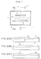
- a 2,000 ⁇ thick silicon oxide film was deposited on the substrate as a base film using RF sputtering, and the resulting silicon oxide film was treated in nitrogen plasma.
- a plasma treating apparatus was of a parallel plane type as shown schematically in FIG. 1. It comprises a chamber 11, a gas inlet system 12, an evacuation system 13, an RF power source 14, and nickel-alloy electrodes 15 and 16, so that the substrate 17 may be placed under an RF plasma 18.
- the plasma treatment was performed for a duration of 5 minutes by applying an RF power of 20 W or 60 W under a reaction pressure of 10 Pa (where, a vacuum degree of 10 ⁇ 3 Pa or lower is achieved), while flowing nitrogen as the reactive gas at a flow rate of 100 SCCM (standard cubic centimeters per minute) and setting the substrate temperature to 200 °C.
- a 1,500 ⁇ thick amorphous silicon film was deposited by plasma CVD, and after removing hydrogen from the film by keeping it at a temperature of 430 °C for 1 hour, solid phase growth was allowed to take place thereon in the temperature range of from 500 to 580 °C for a duration of from 10 minutes to 8 hours.
- the solid phase growth may be carried out by irradiating a laser light thereto before or after or at the same time as heating in the above temperature range.
- the above steps may be performed otherwise using, for example, an apparatus having two or more chambers as shown in FIG. 5, so that the steps can be performed continuously.
- the above processes comprise depositing the amorphous silicon film after once exposing the plasma-treated silicon oxide base to air.
- the process according to the present invention is sensitive to the surface conditions, and the characteristics of the resulting crystalline silicon film tend to be greatly influenced by the inclusions which may adhere to the surface of the substrate during its exposure to air.
- the apparatus illustrated in FIG. 5 it comprises a chamber 501 which is a sputtering apparatus, and a plasma is generated by supplying electric power to two electrodes (sample holder and a backing plate) 502 and 503 from an RF power source 504.
- a substrate 506, which is the sample, and a target 505 are placed on the respective electrodes.
- the target 505 in this case is silicon oxide.
- the chamber 501 is further equipped with a gas system 507 for introducing a gas mixture comprising oxygen gas and argon gas, and another gas system 508 for introducing nitrogen gas.
- An evacuation system 509 is also provided to the chamber 501.
- the apparatus further comprises a chamber 521 which is a plasma CVD apparatus of a parallel plane type.
- a plasma can be generated inside the chamber 521 by supplying an electric power from a power source 524 to two electrodes 522 and 523 provided inside the chamber 521.
- a sample substrate 525 is mounted on the electrode 522 so that a coating which generates by a plasma reaction would form on the substrate upon introducing a gas mixture of silane and hydrogen into the chamber through a gas system 526.
- a mechanism is provided to those chambers as such that the substrate can be heated to a proper temperature.
- An additional chamber 510 in which a substrate 511 is placed, is provided between the two plasma chambers.
- nitrogen plasma treatment is performed immediately after the completion of silicon oxide film deposition using sputtering in the chamber 501, by replacing the atmosphere inside the chamber with nitrogen. If a silicon oxide target should remain inside the chamber, further deposition of silicon oxide film occurs by sputtering. To prevent this from occurring, the RF power must be lowered or the silicon oxide target must be isolated from the plasma. Fortunately, as described hereinafter, plasma treatment is performed optimally at a power of 60 W or lower, and preferably, at a power of 20 W, as compared to an RF power of 100 W or higher required for sputtering. Accordingly, no deposition of silicon oxide occurred during the treatment in nitrogen plasma. To further assure the process, however, a chamber for depositing the silicon oxide film is preferably installed separately from the chamber for use in plasma treatment. An amorphous silicon film thus deposited was also subjected to solid-phase crystallization under the same conditions described hereinbefore.
- the crystallization proceeds as a function of the RF power applied at the plasma treatment. More specifically, the crystallization proceeds rather sluggishly when plasma treatment is performed under a low power of 20 W. At least an annealing for a duration of 1 hour is necessary to crystallize the amorphous silicon film at 550 °C. In other words, the latent period in this case is 1 hour. However, after the passage of an hour, the crystallization proceeds swiftly to attain a saturated state within 2 hours of annealing. By comparing the Raman peak intensity, it can be seen that a crystallization degree well comparable to that of a standard sample, i.e., a single crystal silicon, is achieved for the sample after the annealing of 2 hours.
- crystallization proceeds relatively swiftly in the case a high RF power of 60 W is applied at the plasma treatment.
- an annealing for 4 hours allows the amorphous silicon film to crystallize at a temperature as low as 480 °C, and by increasing the temperature to 550 °C, an annealing for a duration of mere 10 minutes (i.e., a latent period of 10 minutes) initiates crystallization and achieves a saturated state in an hour.
- the degree of crystallization is low, and by comparing the Raman intensity, it can be seen that the degree of crystallization achieve in this case only corresponds to less than 70 % of that obtained for a silicon film crystallized under a low power of 20 W.
- nuclei generate at a low density when the plasma treatment is applied under a low power condition, because the concentration of the catalytic substance is low.
- the crytallization of these nuclei requires a treatment at a high temperature and a long duration.
- the resulting crystallites have high crystallinity and yield a high Raman intensity ratio.
- catalytic substances are generated at a high concentration by applying a plasma treatment under a condition of high power. Since nucleation occurs at high nuclei interfere each other during their growth, and the film which is obtained as a result has a poor crystallinity.
- the application of a plasma treatment enables crystallization to take place at a low temperature and within a short period of time as compared to the case with no plasma treatment.
- the crystallization at a low temperature and in a short period of time is achieved by applying a plasma treatment.
- the concentration of the catalytic substance was controlled by controlling the RF power, however, other factors, such as the pressure applied during the plasma treatment, the type and the component of gas, the temperature of the sample, and the duration of processing, are all important factors for controlling the concentration of the catalytic substance.
- a process for selectively crystallizing an amorphous silicon film by selectively treating the oxide film base using a plasma treatment is described below.
- a 2,000 ⁇ thick silicon oxide film 22 was deposited as a base on a Corning #7059 substrate 21 by sputtering, and a heat-resistant photoresist 24 was applied thereon by spin-coating.
- the entire substrate was exposed to nitrogen plasma in the same manner as in Example 1 to perform plasma treatment on the exposed portion 23 of the oxide film base.
- the plasma treatment was effected under the same conditions as those employed in Example 1, except for setting the RF power to 60 W.
- FIG. 2(A) A process for selectively crystallizing an amorphous silicon film by selectively treating the oxide film base using a plasma treatment.
- the masking material to be used herein must at least resist to the same temperature. Furthermore, preferably, the masking material is removable without using a plasma. Thus, the use of a heat-resistant photoresist for the mask is preferred from these points of view. Otherwise, inorganic materials such as titanium nitride, silicon oxide, and silicon nitride can be used as well.
- an annealing at 550 °C for a duration of 4 hours is performed after depositing a 1,500 ⁇ thick amorphous silicon film 25 by low pressure CVD.
- crystalline silicon 26 was observed to form around the portions remained uncovered by the masking material on plasma treatment.
- the crystallization extended into portions covered by the masking material (but only portions treated by the plasma) for about 5 ⁇ m along the longitudinal direction. No crystallization was observed to occur on other portions 27 covered by the masking material.
- the annealing may be carried out by irradiating a laser light thereto before or after or at the same time as heating at 550°C as described above.
- the crystallinity for the portions subjected to plasma treatment were lower than that of the peripheral portions at a distance of 5 ⁇ m from those plasma-treated portions.
- the fact is that the crystallites initiate growth from a plurality of independent nuclei, and that then they collide with each other to interfere their growth.
- the peripheral portions contain no nucleus, and the direction of crystal growth is confined to a single direction. It can be seen that the crystal growth is allowed to take place without any limitations.
- a process for fabricating a TFT having particularly high mobility by selectively performing a plasma treatment is described below. More specifically, the masking material was formed only on a portion for fabricating a channel forming region (i.e., a region located under the gate contact and between a source and a drain in an island-like semiconductor region) of a TFT to prevent this portion from being exposed to plasma.
- a channel forming region i.e., a region located under the gate contact and between a source and a drain in an island-like semiconductor region
- this process is not suitable for a device having loo long a channel length and too wide a channel width.
- the surface of the silicon oxide base is subject to defects due to the impact exerted by the plasma.
- various types of foreign matter adhere to the surface.
- a part of these defects and foreign matter functions as a catalyst to accelerate nucleation, however, it also may cause leak current if it is found in the channel forming region of a TFT.
- a TFT having high mobility can be obtained only by using semiconductors of high crystallinity.
- the peripheral portions are preferred to the plasma treated portions in this case.
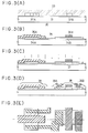
- a 2,000 ⁇ thick silicon oxide film 31 was deposited as a base on a Corning #7059 substrate 30 by sputtering, and a heat-resistant photoresist was applied thereon to form masks 32A and 32B each at the same size as the channel, i.e., 5 ⁇ m x 15 ⁇ m. Otherwise, the mask can be patterned using the patterning for the gate connection, because, as described hereinafter, the effect is the same for both considering that the crystallization is effected after patterning the amorphous silicon film.
- the resulting substrate was placed into a plasma 33 to perform the plasma treatment as shown in FIG. 3(A).
- the same plasma treating apparatus as that used in EXAMPLE 1 was used.
- the plasma treatment was performed for a duration of 5 minutes by applying an RF power of 60 W under a reaction pressure of 10 Pa (where, a vacuum degree of 10 ⁇ 3 Pa or lower is achieved), while flowing nitrogen as the reactive gas at a flow rate of 100 SCCM (standard cubic centimeters per minute) and maintaining the substrate temperature to 200 °C.
- the masks 32A and 32B were removed after the plasma treatment, and a 1,500 ⁇ thick amorphous silicon film was deposited thereon by low pressure CVD using monosilane (SiH4) as the material gas. Subsequently, annealing was effected at 550 °C for a duration of 4 hours to allow the film to crystallize. A laser light may be irradiated to the film for crystallization of the film before or after or at the same time as the annealing. The thus crystallized film was patterned to form island-like silicon regions 34A and 34B, and this was followed by the deposition of a 1,000 ⁇ thick silicon oxide film 35 by plasma CVD using tetraethoxysilane (TEOS) and oxygen as the material gases. After depositing an N-type polysilicon film by low pressure CVD, the resulting structure was subjected to patterning to form a gate connection with gate contact 36A and 36B. The resulting structure is shown in FIG. 3(B).
- TEOS
- phosphine (PH3) gas and diborane (B2H6) gas were used as the N-type and P-type impurity sources, respectively.
- Phosphine was doped by applying an accelerating voltage of 80 keV, and diborane was doped under a voltage of 65 keV.
- the impurity region 37 was formed by further annealing the structure at 550 °C for 4 hours to activate the impurities.
- the activation of the impurities can be performed by a method using an optical energy, such as laser annealing and flash lamp annealing.
- the resulting structure is shown in FIG. 3(C).
- a 5,000 ⁇ thick silicon oxide film was deposited as an interlayer insulator 38 in the same manner as in an ordinary process for fabricating a TFT.
- connection and contacts 39A and 39B were formed in the source region and the drain region.
- FIG. 3(D) the final structure of the TFT as shown in FIG. 3(D).
- FIG. 3(E) The final structure of the TFT circuit as viewed from the upper side is given in FIG. 3(E).
- the cross section views in FIGs. 3(A) to 3(D) are taken along the dashed line drawn in FIG. 3(E).
- the TFT thus obtained was found to have a field-effect mobility of from 40 to 60 cm2/Vs in the N-channel type, and of from 30 to 50 cm2/Vs in the P-channel type.
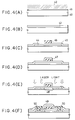
- a 2,000 ⁇ thick silicon oxide film 41 was deposited as a base on a Corning #7059 substrate 40 by sputtering, and the entire substrate was exposed to plasma 42 as shown in FIG. 4(A) to effect the plasma treatment.
- the same plasma treatment apparatus as that used in EXAMPLE 1 was employed.
- the plasma treatment was performed for a duration of 5 minutes by applying an RF power of 60 W under a reaction pressure of 10 Pa (where, a vacuum degree of 10 ⁇ 3 Pa or lower is achieved), while flowing argon as the reactive gas at a flow rate of 100 SCCM (standard cubic centimeters per minute) and maintaining the substrate temperature to 200 °C.
- a 1,500 ⁇ thick amorphous silicon film 43 was deposited thereon by low pressure CVD using monosilane (SiH4) as the material gas.
- annealing was effected at 550 °C for a duration of 4 hours to allow the film to crystallize.
- a laser light may be irradiated to the film for the crystallization of the film before or after or at the same time as the annealing.
- the resulting structure is shown in FIG. 4(B).
- the thus crystallized film was patterned to form an island-like silicon region 44, and this was followed by the deposition of a 1,000 ⁇ thick silicon oxide film 45 by plasma CVD using tetraethoxysilane (TEOS) and oxygen as the material gases. After depositing a 5,000 ⁇ thick aluminum film containing 1 % of silicon by sputtering, the aluminum film was patterned to form a gate connection and contact 46. The resulting structure is shown in FIG. 4(C).
- TEOS tetraethoxysilane
- the entire substrate was subjected to anodic oxidation by dipping it into an ethylene glycol solution containing 3 % of tartaric acid and applying current between a platinum cathode and the aluminum connection 46 (anode).
- the current was applied in such a manner that the voltage thereof would increase in the initial state at a rate of 2 V/minute, and that a constant voltage is maintained after a voltage of 220 V is attained.
- the current was turned off at the point the current dropped to 10 ⁇ A/m2 or lower.
- a 2,000 ⁇ thick anodic oxide 47 as shown in FIG. 4(D).
- phosphine (PH3) gas and diborane (B2H6) gas were used as the N-type and P-type impurity sources, respectively.
- Phosphine was doped by applying an accelerating voltage of 80 keV, and diborane was doped under a voltage of 65 keV.
- the impurity region 48 was formed by further laser annealing the structure applying 5 shots using a KrF excimer laser operating at a wavelength of 248 nm and emitting a laser beam at an energy denity of from 250 to 300 mJ/cm2. The resulting structure is shown in FIG. 4(E).
- the TFT thus obtained was found to have a field-effect mobility of from 40 to 60 cm2/Vs in the N-channel type, and of from 30 to 50 cm2/Vs in the P-channel type. Furthermore, a shift resistor fabricated using this TFT was observed to operate at 6 MHz with a drain voltage of 17 V, and at 11 MHz with a drain voltage of 20 V.
- a process which comprises selectively crystallizing an amorphous silicon film by selectively treating the oxide film base using a plasma treatment, and further enhancing the crystallization by irradiating a laser light is described below.
- the present example comprises a treatment using laser irradiation in addition to the process described in EXAMPLE 2.
- a 2,000 ⁇ thick silicon oxide film 22 was deposited as a base on a Corning #7059 substrate 21 by sputtering, and a heat-resistant photoresist 24 was applied thereon by spin-coating. After patterning the resulting photoresist film 24, the entire substrate was exposed to nitrogen plasma in the same manner as in Example 1 to perform plasma treatment on the exposed portion 23 of the oxide film base. The plasma treatment was effected under the same conditions as those employed in Example 1, except for setting the RF power to 20 W. Thus was obtained a structure shown in FIG. 8(A).
- the masking material to be used herein must at least resist to the same temperature. Furthermore, preferably, the masking material is removable without using a plasma. Thus, the use of a heat-resistant photoresist for the mask is preferred from these points of view. Otherwise, inorganic materials such as titanium nitride, silicon oxide, and silicon nitride can be used as well.
- an annealing at 550 °C for a duration of 4 hours is performed after depositing a 1,500 ⁇ thick amorphous silicon film 25 by reduced pressure CVD.
- crystalline silicon 26 was observed to form around the portions remained uncovered by the masking material on plasma treatment.
- the crystallization extended into portions covered by the masking material (but only portions treated by the plasma) for about 5 ⁇ m along the longitudinal direction. No crystallization was observed to occur on other portions 27 covered by the masking material.
- a laser beam 80 was irradiated to the resulting structure.
- the laser annealing was performed by irradiating 2 shots using a KrF excimer laser operating at a wavelength of 248 nm and a pulse width of 20 nsec, and emitting a laser beam at an energy density of from 200 to 400 mJ/cm2.
- the temperature of the substrate was maintained in the temperature range of from 150 to 300 °C, for instance, at 200 °C by heating, to make the best of the effect exerted by laser irradiation.
- Other usable laser light include those emitted from a XeC1 excimer laser operating at a wavelength of 308 nm and an Arf excimer laser operating at a wavelength of 193 nm. Otherwise, an intense light may be irradiated in the place of a laser light.
- RTA rapid thermal annealing
- a silicon film having a favorable crystallinity can be obtained by employing any of the aforementioned methods.
- the crystallized region 26 obtained as a result of thermal annealing was found to change into a silicon film 26' having a further improved crystallinity.
- a polycrystalline film 27' was obtained from the region remained uncrystallized 27 as a result of laser irradiation.
- This film 27' though apparently modified, was confirmed to have poor crystallinity by Raman spectroscopy. Furthermore, observation by transmission electron microscope revealed that numerous minute crystallites constitute the film 27', and that grain-oriented relatively large crystallites constitute the film 26'.
- the resulting crystallized silicon film 26' was processed into island-like portions in the same manner as in EXAMPLE 3 (see FIG. 3) to obtain a TFT with considerably improved characteristics. More specifically, an N-channel TFT fabricated using the silicon film obtained in the present example yielded a field-effect mobility in the range of from 150 to 200 cm2/Vs and a threshold voltage of from 0.5 to 1.5 V, which are in clear contrast with the values obtained on a previously obtained TFT using the silicon film obtained in EXAMPLE 2, namely, a mobility in the range of from 50 to 90 cm2/Vs and a threshold value of 3 to 8 V. It can be seen that the mobility is greatly increased, and that the fluctuation in the threshold voltage is considerably decreased.
- the above improvements in characteristics were only achievable by laser crystallization of the amorphous silicon film.
- the silicon films which were obtained by a prior art process by laser crystallization had considerable fluctuation in the film characteristics. Moreover, they could not be fabricated by mass production because the crystallization thereof required a temperature of 400 °C or higher and an irradiation of a laser beam at an energy density of 350 mJ/cm2 or higher.
- the process according to the present example can be performed at a substrate temperature lower than the conventional one and by irradiating a laser beam at a far lower energy density.
- films of uniform quality can be obtained by the process according to the present invention at a yield well comparable to those fabricated by solid phase growth crystallization according to a conventional thermal annealing process. Thus, the TFTs fabricated therefrom also exhibited uniform characteristics.
- the process according to the present example provides a silicon film whose insufficient crystallinity is compensated by the effect of laser irradiation. Accordingly, silicon films containing nickel at a low concentration were also made usable in TFTs by the process of the present example without impairing the characteristics of the resulting TFT. Thus, devices containing less nickel in the active layer region, i.e., those more favorable from the viewpoint of electric stability and reliability, could be implemented.
- the present example provides a process for introducing a catalytic element into the amorphous silicon film by coating the upper surface of the amorphous film with a solution prepared by introducing a catalytic element which accelerates the crystallization.
- the catalytic element is selectively introduced to allow the crystallites in this region to grow into the portions remained free from the catalytic elements. In this manner, crystalline silicon film can be obtained without increasing the concentration of the catalytic element.
- a silicon oxide film 902 was deposited on a Corning #7059 substrate 901 (10 cm2 in size) by sputtering or by plasma CVD. Then, after depositing a 1,000 ⁇ thick amorphous silicon film by plasma CVD, a 500 ⁇ thick silicon oxide film 905 was deposited by sputtering to provide a protective coating. To this structure was dropped 5 ml (for a 10-cm2 square substrate) of an acetate solution added therein 100 ppm by weight of nickel. A spinner 900 was operated at 50 rpm for a duration of 10 seconds to effect spin coating, thereby forming a uniform aqueous film 907 over the entire surface of the substrate.
- the resulting structure was subjected to 60 seconds of spin drying by operating the spinner 900 at a rate of 2,000 rpm.
- the retention above may be otherwise conducted by applying a spinner rotating at 150 rpm or lower.
- the amorphous silicon film 904 was crystallized by heating it at 550 °C under a nitrogen atmosphere for a duration of 8 hours.
- the crystal growth takes place during the heat treatment in such a manner that the crystals grow transversely along a direction indicated with an arrow 916, from a region 906 into which nickel was introduced to a region 903 free from the incorporation of nickel.
- crystallization occurs also in the region 904 into which nickel was introduced directly.
- the crystallization occurs on the region 904 into which nickel had been directly introduced, and also on the region 903 in which the crystallization proceeds along a transverse direction.
- the concentration distribution for nickel in the region 903 is illustrated in FIG. 10.
- the distribution curve in FIG. 10 is based on the data of nickel concentration obtained by SIMS (secondary ion mass spectroscopy). It is confirmed that the nickel concentration in the region 904 into which nickel had been directly introduced is about a digit or more higher than the concentration shown in the graph of FIG. 10.
- the nickel concentration distribution illustrated in the graph of FIG. 10 can be controlled by controlling the nickel concentration of the solution.
- the nickel concentration of the solution was adjusted to 100 ppm.
- crystallization also occurs even if the concentration of the solution is set to 10 ppm.
- the nickel concentration in the region 903 in FIG. 9 can be further lowered by a digit by setting the nickel concentration of the solution to 10 ppm.
- a problem newly arises by decreasing the nickel concentration of the solution, because the distance 916 of crystal growth along the transverse direction is shortened.
- Example 5 it is also effective to further improve the crystallinity of the crystalline silicon film thus obtained by irradiating a laser beam or an intense light equivalent thereto in the similar manner as in EXAMPLE 5.
- the morphology of the film was impaired because, due to nickel included at a relatively high concentration, nickel precipitated from the silicon film to form grains of nickel silicide from about 0.1 to 10 ⁇ m in size in the silicon film.
- the nickel concentration can be far lowered in the present case. Accordingly, no precipitation of nickel silicide is found to form, and surface roughening of the film due to laser irradiation can be prevented from occurring.
- the crystalline silicon film thus subjected to crystallization can be used directly in the active layer of a TFT.
- the use of the region 903 as the active layer of a TFT is extremely useful because this region contain catalytic elements at a very low concentration.
- the process for fabricating a TFT using the crystalline silicon film above comprises, as shown in FIG. 9(B) and the subsequent figures, etching the silicon film into an island-like portion to form an island-like silicon region 908.
- the resulting structure is subjected to an oxidizing atmosphere in the temperature range of from 500 to 750 °C, preferably in the range of from 550 to 650 °C, to form a silicon oxide film 909 which functions as a gate insulator film on the surface of the silicon region.
- the oxidizing reaction can be further accelerated by incorporating water vapor, nitrous oxide, and the like into the atmosphere.
- a known vapor phase growth process such as plasma CVD and sputtering can be used as an alternative means for forming the silicon oxide film 909, instead of performing the aforementioned thermal oxidation step.
- connection 910 which functions as a gate contact is formed using a material capable of being anodically oxidized, such as aluminum, is formed in such a manner that it may transverse the island-like silicon region.
- a material capable of being anodically oxidized such as aluminum
- aluminum preferably, aluminum containing from 0.05 to 0.3 % by weight of scandium is used herein to prevent hillock from occurring.
- connection 910 was anodically oxidized to form a 0.1 to 1 ⁇ m thick anodically oxidized film 911 on the surface thereof.
- the resulting structure is shown in FIG. 9(C).
- an impurity was introduced into the structure using plasma doping.
- phosphine (PH3) gas was used as the doping gas.
- Phosphine was doped at an accelerating voltage of 80 keV, and the thus doped impurity was activated by further laser annealing the structure applying 5 shots of laser using a KrF excimer laser operating at a wavelength of 248 nm and emitting a laser beam at an energy density of from 250 to 300 mJ/cm2.
- the impurity regions 912 and 913 are formed.
- the gate contact is offset from the impurity region by a distance corresponding to the thickness x of the anodic oxide.
- the resulting structure is shown in FIG. 9(D).
- a 5,000 ⁇ thick silicon oxide film was deposited as an interlayer insulator 914 in the same manner as in an ordinary process for fabricating a TFT. Additionally, a light-transmitting polyimide film 915 was formed by spin coating to form a further smoother surface. By forming contact holes in the resulting film, connection and contacts 917 and 918 were formed in the source region and the drain region. Thus was obtained the final structure of the TFT as shown in FIG. 9(E).
- an acetate solution was used as the solution containing the catalytic element.
- an aqueous solution, a solution based on an organic solvent, etc., which is selected from a wide variety, can be used as well.
- the catalytic element may not be included in the solution as a compound, and it may be simply dispersed in the solution.
- the catalytic element can be incorporated into a solvent selected from polar solvents, for example, water, an alcohol, an acid, and ammonia.
- polar solvents for example, water, an alcohol, an acid, and ammonia.
- nickel When nickel is selected as the catalytic element, nickel is incorporated into a polar solvent by using a nickel compound.
- the nickel compounds to be used for this purpose include, representatively, nickel bromide, nickel acetate, nickel oxalate, nickel carbonate, nickel chloride, nickel iodide, nickel nitrate, nickel sulfate, nickel formate, nickel acetylacetate, nickel 4-cyclohexylbutyrate, nickel oxide, and nickel hydroxide.
- Solvents to be used in the present invention include a non-polar solvent such as benzene, toluene, xylene, carbon tetrachloride, chloroform, and ethers.
- nickel is introduced in the form of a nickel compound.
- the nickel compounds to be used for this purpose include nickel acetylacetate and nickel 2-ethylhexanate.
- a surfactant in the solution containing the catalytic element.
- the incorporation increases the adhesion strength of the solution to the coating surface and controls the adsorptivity. Otherwise, the surfactant may be previously applied to the surface to be coated with the solution.
- metallic nickel When metallic nickel is used as the catalytic element, it must be previously dissolved in an acid to use it in the form of a solution thereof.
- the foregoing cases refer to examples using a solution into which the catalytic element, nickel, is completely dissolved.
- Nickel need not be completely dissolved in the solution, and materials in an other form, for instance, an emulsion comprising a powder of metallic nickel or a powder of a compound of nickel uniformly dispersed in a dispersion medium can be used as well.
- a non-polar solution such as a toluene solution of nickel 2-ethylhexanate can be directly applied to the surface of an amorphous silicon film.
- it is also effective to previously coat the amorphous silicon film with an adhesive generally used in coating a resist.
- the use thereof must be done carefully, because the application thereof in too large an amount reversely interferes the addition of the catalytic element into the amorphous silicon film.
- the catalytic element is incorporated into the solution approximately in an amount of, though depending on the type of the solution, from 1 to 200 ppm by weight, and preferably, from 1 to 50 ppm by weight. This range of addition is determined by taking the nickel concentration of the crystallized film and the resistance against hydrofluoric acid into consideration.
- the present invention is epoch-making in that it enables the crystallization of an amorphous silicon to take place at an even lower temperature and within a shorter period of time. Furthermore, the process according to the present invention is suitable for mass production, and yet, it can be performed employing the most commonly used equipments, apparatuses, and methods. Accordingly, it is a promising and a beneficial process for the electronic industry.
- a conventional solid phase growth process requires an annealing step for a duration of at least 24 hours.
- the process time per substrate is preferably 2 minutes, 15 annealing furnaces are necessary to make the process practically feasible.
- the present invention allows the process to complete within 8 hours, and under optimal conditions, the process can be even more shortened to a mere 4 hours or less. This signifies that the process can be performed while reducing the number of furnaces to only a sixth or less of the above calculated number.
- economical TFTs can be produced, and this might call novel demands.
- the present invention is greatly beneficial for the industry.
Landscapes
- Recrystallisation Techniques (AREA)
- Thin Film Transistor (AREA)
Priority Applications (2)
| Application Number | Priority Date | Filing Date | Title |
|---|---|---|---|
| EP01124710A EP1207549A3 (fr) | 1993-02-03 | 1994-02-02 | Procédé de fabrication d'un composant à base de semiconducteur |
| EP99124492A EP0997950A3 (fr) | 1993-02-03 | 1994-02-02 | Procédé d amélioration de crystallisation des couches semi-conductrices particulièrement pour transistors à couches minces |
Applications Claiming Priority (2)
| Application Number | Priority Date | Filing Date | Title |
|---|---|---|---|
| JP39499/93 | 1993-02-03 | ||
| JP03949993A JP3497198B2 (ja) | 1993-02-03 | 1993-02-03 | 半導体装置および薄膜トランジスタの作製方法 |
Related Child Applications (2)
| Application Number | Title | Priority Date | Filing Date |
|---|---|---|---|
| EP99124492A Division EP0997950A3 (fr) | 1993-02-03 | 1994-02-02 | Procédé d amélioration de crystallisation des couches semi-conductrices particulièrement pour transistors à couches minces |
| EP01124710A Division EP1207549A3 (fr) | 1993-02-03 | 1994-02-02 | Procédé de fabrication d'un composant à base de semiconducteur |
Publications (2)
| Publication Number | Publication Date |
|---|---|
| EP0609867A2 true EP0609867A2 (fr) | 1994-08-10 |
| EP0609867A3 EP0609867A3 (fr) | 1995-01-11 |
Family
ID=12554743
Family Applications (3)
| Application Number | Title | Priority Date | Filing Date |
|---|---|---|---|
| EP94101571A Ceased EP0609867A3 (fr) | 1993-02-03 | 1994-02-02 | Procédé de fabrication d'une couche semi-conductrice cristallisée et procédé de fabrication d'un dispositif semi-conducteur l'utilisant. |
| EP01124710A Withdrawn EP1207549A3 (fr) | 1993-02-03 | 1994-02-02 | Procédé de fabrication d'un composant à base de semiconducteur |
| EP99124492A Withdrawn EP0997950A3 (fr) | 1993-02-03 | 1994-02-02 | Procédé d amélioration de crystallisation des couches semi-conductrices particulièrement pour transistors à couches minces |
Family Applications After (2)
| Application Number | Title | Priority Date | Filing Date |
|---|---|---|---|
| EP01124710A Withdrawn EP1207549A3 (fr) | 1993-02-03 | 1994-02-02 | Procédé de fabrication d'un composant à base de semiconducteur |
| EP99124492A Withdrawn EP0997950A3 (fr) | 1993-02-03 | 1994-02-02 | Procédé d amélioration de crystallisation des couches semi-conductrices particulièrement pour transistors à couches minces |
Country Status (6)
| Country | Link |
|---|---|
| US (1) | US6610142B1 (fr) |
| EP (3) | EP0609867A3 (fr) |
| JP (1) | JP3497198B2 (fr) |
| KR (5) | KR0168693B1 (fr) |
| CN (5) | CN100416750C (fr) |
| TW (1) | TW266315B (fr) |
Cited By (8)
| Publication number | Priority date | Publication date | Assignee | Title |
|---|---|---|---|---|
| JPH0855848A (ja) * | 1994-08-11 | 1996-02-27 | Semiconductor Energy Lab Co Ltd | 酸化珪素膜の加熱処理方法 |
| EP1119053A2 (fr) | 1993-02-15 | 2001-07-25 | Semiconductor Energy Laboratory Co., Ltd. | Semiconducteur, dispositif semiconducteur, et méthode pour sa fabrication |
| US6613613B2 (en) | 1994-08-31 | 2003-09-02 | Semiconductor Energy Laboratory Co., Ltd. | Thin film type monolithic semiconductor device |
| EP1445802A1 (fr) * | 2003-02-06 | 2004-08-11 | Centre National De La Recherche Scientifique (Cnrs) | Transistor pour dispositif d'affichage à matrice active, dispositif d'affichage comprenant un tel transistor et son procédé de fabrication |
| US6997985B1 (en) | 1993-02-15 | 2006-02-14 | Semiconductor Energy Laboratory Co., Ltd. | Semiconductor, semiconductor device, and method for fabricating the same |
| US7465958B2 (en) | 2004-03-12 | 2008-12-16 | Semiconductor Energy Laboratory Co., Ltd. | Thin film transistor, semiconductor device, and method for manufacturing the same |
| WO2008104346A3 (fr) * | 2007-02-27 | 2008-12-31 | Zeiss Carl Laser Optics Gmbh | Installation de revêtement en continu, procédés de production de films minces cristallins et de cellules solaires, et cellule solaire |
| US7550765B2 (en) | 1994-08-19 | 2009-06-23 | Semiconductor Energy Laboratory Co., Ltd. | Semiconductor device and fabrication method thereof |
Families Citing this family (63)
| Publication number | Priority date | Publication date | Assignee | Title |
|---|---|---|---|---|
| KR100306527B1 (ko) | 1994-06-15 | 2002-06-26 | 구사마 사부로 | 박막반도체장치의제조방법,박막반도체장치 |
| US5834827A (en) * | 1994-06-15 | 1998-11-10 | Seiko Epson Corporation | Thin film semiconductor device, fabrication method thereof, electronic device and its fabrication method |
| US5915174A (en) * | 1994-09-30 | 1999-06-22 | Semiconductor Energy Laboratory Co., Ltd. | Semiconductor device and method for producing the same |
| JP4130237B2 (ja) * | 1995-01-28 | 2008-08-06 | 株式会社半導体エネルギー研究所 | 結晶性珪素膜の作製方法及び半導体装置の作製方法 |
| TW305063B (fr) | 1995-02-02 | 1997-05-11 | Handotai Energy Kenkyusho Kk | |
| US7075002B1 (en) | 1995-03-27 | 2006-07-11 | Semiconductor Energy Laboratory Company, Ltd. | Thin-film photoelectric conversion device and a method of manufacturing the same |
| TW463378B (en) | 1995-06-01 | 2001-11-11 | Semiconductor Energy Lab | Method of manufacturing semiconductor device |
| US6228751B1 (en) | 1995-09-08 | 2001-05-08 | Semiconductor Energy Laboratory Co., Ltd. | Method of manufacturing a semiconductor device |
| TW371796B (en) | 1995-09-08 | 1999-10-11 | Semiconductor Energy Lab Co Ltd | Method and apparatus for manufacturing a semiconductor device |
| JP3235817B2 (ja) * | 1995-09-21 | 2001-12-04 | シャープ株式会社 | 半導体回路、半導体装置およびそれらの製造方法 |
| US6204101B1 (en) | 1995-12-15 | 2001-03-20 | Semiconductor Energy Laboratory Co., Ltd. | Method of manufacturing semiconductor device |
| TW319912B (fr) * | 1995-12-15 | 1997-11-11 | Handotai Energy Kenkyusho Kk | |
| US6478263B1 (en) | 1997-01-17 | 2002-11-12 | Semiconductor Energy Laboratory Co., Ltd. | Semiconductor device and its manufacturing method |
| JP3645378B2 (ja) | 1996-01-19 | 2005-05-11 | 株式会社半導体エネルギー研究所 | 半導体装置の作製方法 |
| JP3645380B2 (ja) | 1996-01-19 | 2005-05-11 | 株式会社半導体エネルギー研究所 | 半導体装置の作製方法、情報端末、ヘッドマウントディスプレイ、ナビゲーションシステム、携帯電話、ビデオカメラ、投射型表示装置 |
| JP3729955B2 (ja) | 1996-01-19 | 2005-12-21 | 株式会社半導体エネルギー研究所 | 半導体装置の作製方法 |
| JP3645379B2 (ja) * | 1996-01-19 | 2005-05-11 | 株式会社半導体エネルギー研究所 | 半導体装置の作製方法 |
| US6180439B1 (en) | 1996-01-26 | 2001-01-30 | Semiconductor Energy Laboratory Co., Ltd. | Method for fabricating a semiconductor device |
| US7056381B1 (en) | 1996-01-26 | 2006-06-06 | Semiconductor Energy Laboratory Co., Ltd. | Fabrication method of semiconductor device |
| TW335503B (en) | 1996-02-23 | 1998-07-01 | Semiconductor Energy Lab Kk | Semiconductor thin film and manufacturing method and semiconductor device and its manufacturing method |
| TW374196B (en) | 1996-02-23 | 1999-11-11 | Semiconductor Energy Lab Co Ltd | Semiconductor thin film and method for manufacturing the same and semiconductor device and method for manufacturing the same |
| TW317643B (fr) | 1996-02-23 | 1997-10-11 | Handotai Energy Kenkyusho Kk | |
| JP3476320B2 (ja) * | 1996-02-23 | 2003-12-10 | 株式会社半導体エネルギー研究所 | 半導体薄膜およびその作製方法ならびに半導体装置およびその作製方法 |
| US6100562A (en) | 1996-03-17 | 2000-08-08 | Semiconductor Energy Laboratory Co., Ltd. | Method of manufacturing a semiconductor device |
| US8603870B2 (en) | 1996-07-11 | 2013-12-10 | Semiconductor Energy Laboratory Co., Ltd. | Semiconductor device and method of manufacturing the same |
| TW556263B (en) | 1996-07-11 | 2003-10-01 | Semiconductor Energy Lab | Semiconductor device and method of manufacturing the same |
| US6369410B1 (en) | 1997-12-15 | 2002-04-09 | Semiconductor Energy Laboratory Co., Ltd. | Semiconductor device and method of manufacturing the semiconductor device |
| US6396147B1 (en) | 1998-05-16 | 2002-05-28 | Semiconductor Energy Laboratory Co., Ltd. | Semiconductor device with metal-oxide conductors |
| US6362027B1 (en) | 1998-07-08 | 2002-03-26 | Semiconductor Energy Laboratory Co., Ltd. | Semiconductor device, active matrix substrate, method of manufacturing the semiconductor device and method of manufacturing the active matrix substrate |
| JP3592535B2 (ja) | 1998-07-16 | 2004-11-24 | 株式会社半導体エネルギー研究所 | 半導体装置の作製方法 |
| JP4030193B2 (ja) | 1998-07-16 | 2008-01-09 | 株式会社半導体エネルギー研究所 | 半導体装置の作製方法 |
| US6294441B1 (en) | 1998-08-18 | 2001-09-25 | Semiconductor Energy Laboratory Co., Ltd. | Method of manufacturing a semiconductor device |
| US6380007B1 (en) | 1998-12-28 | 2002-04-30 | Semiconductor Energy Laboratory Co., Ltd. | Semiconductor device and manufacturing method of the same |
| US6878968B1 (en) | 1999-05-10 | 2005-04-12 | Semiconductor Energy Laboratory Co., Ltd. | Semiconductor device |
| US6680487B1 (en) | 1999-05-14 | 2004-01-20 | Semiconductor Energy Laboratory Co., Ltd. | Semiconductor comprising a TFT provided on a substrate having an insulating surface and method of fabricating the same |
| JP4298131B2 (ja) | 1999-05-14 | 2009-07-15 | 株式会社半導体エネルギー研究所 | 液晶表示装置の作製方法 |
| TW459275B (en) | 1999-07-06 | 2001-10-11 | Semiconductor Energy Lab | Semiconductor device and method of fabricating the same |
| JP3599679B2 (ja) * | 2000-04-04 | 2004-12-08 | 松下電器産業株式会社 | 薄膜トランジスタの製造方法 |
| US6913986B2 (en) | 2000-04-04 | 2005-07-05 | Matsushita Electric Industrial Co., Ltd. | Method and apparatus for fabricating a thin film and thin film transistor and method of fabricating same |
| JP4558140B2 (ja) * | 2000-05-02 | 2010-10-06 | 株式会社半導体エネルギー研究所 | 半導体装置の作製方法 |
| JP2001326175A (ja) * | 2000-05-12 | 2001-11-22 | Semiconductor Energy Lab Co Ltd | 半導体装置の作製方法 |
| US6875674B2 (en) | 2000-07-10 | 2005-04-05 | Semiconductor Energy Laboratory Co., Ltd. | Method of manufacturing a semiconductor device with fluorine concentration |
| US7332273B2 (en) | 2002-06-20 | 2008-02-19 | Affymetrix, Inc. | Antireflective coatings for high-resolution photolithographic synthesis of DNA arrays |
| US20070275411A1 (en) | 2006-05-25 | 2007-11-29 | Mcgall Glenn H | Silane mixtures |
| TWI227565B (en) * | 2003-04-16 | 2005-02-01 | Au Optronics Corp | Low temperature poly-Si thin film transistor and method of manufacturing the same |
| KR100738068B1 (ko) * | 2004-08-20 | 2007-07-12 | 삼성전자주식회사 | 산화 환원 반응을 이용한 귀금속 전극 형성 방법 |
| JP4730034B2 (ja) * | 2005-09-20 | 2011-07-20 | 日新電機株式会社 | シリコンドット付き基板の形成方法 |
| JP4497068B2 (ja) * | 2005-09-26 | 2010-07-07 | 日新電機株式会社 | シリコンドット形成方法及びシリコンドット形成装置 |
| WO2008150769A2 (fr) * | 2007-05-31 | 2008-12-11 | Thinsilicon Corporation | Dispositif photovoltaïque et procédé de fabrication de dispositifs photovoltaïques |
| JP5503857B2 (ja) | 2007-09-14 | 2014-05-28 | 株式会社半導体エネルギー研究所 | 薄膜トランジスタの作製方法 |
| JP5311957B2 (ja) * | 2007-10-23 | 2013-10-09 | 株式会社半導体エネルギー研究所 | 表示装置及びその作製方法 |
| JP5311955B2 (ja) | 2007-11-01 | 2013-10-09 | 株式会社半導体エネルギー研究所 | 表示装置の作製方法 |
| US8591650B2 (en) * | 2007-12-03 | 2013-11-26 | Semiconductor Energy Laboratory Co., Ltd. | Method for forming crystalline semiconductor film, method for manufacturing thin film transistor, and method for manufacturing display device |
| US8187956B2 (en) * | 2007-12-03 | 2012-05-29 | Semiconductor Energy Laboratory Co., Ltd. | Method for manufacturing microcrystalline semiconductor film, thin film transistor having microcrystalline semiconductor film, and photoelectric conversion device having microcrystalline semiconductor film |
| JP2009272402A (ja) * | 2008-05-02 | 2009-11-19 | Dainippon Screen Mfg Co Ltd | 基板処理方法および基板処理装置 |
| CN101746547B (zh) * | 2008-12-08 | 2011-04-20 | 中国石油天然气股份有限公司 | 改性沥青包装薄膜袋及其制备方法 |
| WO2010144459A2 (fr) * | 2009-06-10 | 2010-12-16 | Thinsilicon Corporation | Modules photovoltaïques et procédés de production de modules photovoltaïques comprenant des empilements tandem de couches semi-conductrices |
| US8258025B2 (en) * | 2009-08-07 | 2012-09-04 | Semiconductor Energy Laboratory Co., Ltd. | Method for manufacturing microcrystalline semiconductor film and thin film transistor |
| US8343858B2 (en) | 2010-03-02 | 2013-01-01 | Semiconductor Energy Laboratory Co., Ltd. | Method for manufacturing microcrystalline semiconductor film and method for manufacturing semiconductor device |
| CN103634960A (zh) * | 2013-12-06 | 2014-03-12 | 阳泉市新鑫科技研究所有限责任公司 | 等离子氦气和氙气高压气体发热装置 |
| US11158504B2 (en) | 2017-07-31 | 2021-10-26 | Corning Incorporated | Flash-lamp annealing method of making polycrystalline silicon |
| TWI750375B (zh) * | 2018-05-16 | 2021-12-21 | 力智電子股份有限公司 | 溝槽閘極金氧半場效電晶體及其製造方法 |
| CN111564365A (zh) * | 2020-04-10 | 2020-08-21 | 中国科学院微电子研究所 | 一种沉积薄膜的方法及其应用、形成半导体有源区的方法 |
Family Cites Families (47)
| Publication number | Priority date | Publication date | Assignee | Title |
|---|---|---|---|---|
| USRE28385E (en) | 1968-03-20 | 1975-04-08 | Method of treating semiconductor devices | |
| US3556880A (en) | 1968-04-11 | 1971-01-19 | Rca Corp | Method of treating semiconductor devices to improve lifetime |
| US3783049A (en) | 1971-03-31 | 1974-01-01 | Trw Inc | Method of platinum diffusion |
| US4231809A (en) | 1979-05-25 | 1980-11-04 | Bell Telephone Laboratories, Incorporated | Method of removing impurity metals from semiconductor devices |
| JPS57194518A (en) * | 1981-05-27 | 1982-11-30 | Toshiba Corp | Manufacture of polycrystalline silicon |
| JPS5833822A (ja) * | 1981-08-21 | 1983-02-28 | Mitsubishi Electric Corp | 半導体基体の製作方法 |
| JPS58130517A (ja) * | 1982-01-29 | 1983-08-04 | Hitachi Ltd | 単結晶薄膜の製造方法 |
| AT380974B (de) | 1982-04-06 | 1986-08-11 | Shell Austria | Verfahren zum gettern von halbleiterbauelementen |
| JPS58190020A (ja) | 1982-04-30 | 1983-11-05 | Seiko Epson Corp | エピタキシヤル成長法 |
| JPS5983993A (ja) * | 1982-11-02 | 1984-05-15 | Nec Corp | 単結晶半導体層の成長方法 |
| JPS60202952A (ja) * | 1984-03-28 | 1985-10-14 | Fujitsu Ltd | 半導体装置の製造方法 |
| JPH07105338B2 (ja) | 1985-08-07 | 1995-11-13 | 日本電気株式会社 | 半導体装置の製造方法 |
| JPS63142807A (ja) | 1986-12-05 | 1988-06-15 | Nec Corp | 半導体装置の製造方法 |
| US5225355A (en) | 1988-02-26 | 1993-07-06 | Fujitsu Limited | Gettering treatment process |
| US5010037A (en) | 1988-10-14 | 1991-04-23 | California Institute Of Technology | Pinhole-free growth of epitaxial CoSi2 film on Si(111) |
| JPH02140915A (ja) * | 1988-11-22 | 1990-05-30 | Seiko Epson Corp | 半導体装置の製造方法 |
| JP2765968B2 (ja) | 1989-07-27 | 1998-06-18 | 三洋電機株式会社 | 結晶性シリコン膜の製造方法 |
| US5075259A (en) | 1989-08-22 | 1991-12-24 | Motorola, Inc. | Method for forming semiconductor contacts by electroless plating |
| JPH0395922A (ja) * | 1989-09-07 | 1991-04-22 | Canon Inc | 半導体薄膜の形成方法 |
| JPH03138925A (ja) | 1989-10-24 | 1991-06-13 | Kyocera Corp | 半導体膜の結晶化法 |
| JPH03138625A (ja) * | 1989-10-25 | 1991-06-13 | Fujitsu Ltd | 半導体光学装置及びその製造方法 |
| JPH03200319A (ja) | 1989-12-27 | 1991-09-02 | Nec Corp | 多結晶シリコンの形成方法 |
| JP3054422B2 (ja) * | 1990-03-07 | 2000-06-19 | 株式会社東芝 | 半導体装置の製造方法 |
| JPH03257818A (ja) * | 1990-03-07 | 1991-11-18 | Seiko Epson Corp | 半導体装置の製造方法 |
| US5177826A (en) * | 1990-03-16 | 1993-01-12 | Hagemann International | Rotary toothbrush |
| JPH0760807B2 (ja) | 1990-03-29 | 1995-06-28 | 株式会社ジーティシー | 半導体薄膜の製造方法 |
| DE69125886T2 (de) * | 1990-05-29 | 1997-11-20 | Semiconductor Energy Lab | Dünnfilmtransistoren |
| JPH0462976A (ja) * | 1990-06-30 | 1992-02-27 | Nippon Seiki Co Ltd | 加速度センサの製造方法 |
| GB9014723D0 (en) * | 1990-07-03 | 1990-08-22 | Marconi Gec Ltd | Crystallisation process |
| US5147826A (en) * | 1990-08-06 | 1992-09-15 | The Pennsylvania Research Corporation | Low temperature crystallization and pattering of amorphous silicon films |
| JP2650003B2 (ja) | 1991-02-14 | 1997-09-03 | 信越化学工業株式会社 | 化学的気相成長法によるシリコン単結晶の製造方法およびその原料クロロシラン類中の超微量元素と製造されたシリコン単結晶中の超微量元素の分別定量方法 |
| US5289030A (en) * | 1991-03-06 | 1994-02-22 | Semiconductor Energy Laboratory Co., Ltd. | Semiconductor device with oxide layer |
| JP3257818B2 (ja) | 1991-02-27 | 2002-02-18 | 三井化学株式会社 | メタクロレインの製造方法、メタクロレインの製造に用いる触媒及びその触媒の製造方法 |
| JPH05182923A (ja) * | 1991-05-28 | 1993-07-23 | Semiconductor Energy Lab Co Ltd | レーザーアニール方法 |
| GB9114018D0 (en) | 1991-06-28 | 1991-08-14 | Philips Electronic Associated | Thin-film transistor manufacture |
| JPH05109737A (ja) | 1991-10-18 | 1993-04-30 | Casio Comput Co Ltd | 薄膜トランジスタの製造方法 |
| US5244819A (en) | 1991-10-22 | 1993-09-14 | Honeywell Inc. | Method to getter contamination in semiconductor devices |
| JP3204735B2 (ja) * | 1992-06-01 | 2001-09-04 | 株式会社東芝 | 水素化アモルファスシリコン薄膜トランジスタの製造方法 |
| US5288662A (en) | 1992-06-15 | 1994-02-22 | Air Products And Chemicals, Inc. | Low ozone depleting organic chlorides for use during silicon oxidation and furnace tube cleaning |
| JP3280420B2 (ja) | 1992-07-30 | 2002-05-13 | 株式会社紀文フードケミファ | 豆乳を含むカルシウム吸収促進組成物 |
| US5300187A (en) | 1992-09-03 | 1994-04-05 | Motorola, Inc. | Method of removing contaminants |
| US5843225A (en) | 1993-02-03 | 1998-12-01 | Semiconductor Energy Laboratory Co., Ltd. | Process for fabricating semiconductor and process for fabricating semiconductor device |
| US5275851A (en) | 1993-03-03 | 1994-01-04 | The Penn State Research Foundation | Low temperature crystallization and patterning of amorphous silicon films on electrically insulating substrates |
| JP2847031B2 (ja) | 1993-05-03 | 1999-01-13 | 現代電子産業株式会社 | 半導体素子の配線製造方法 |
| JP3200319B2 (ja) | 1994-02-24 | 2001-08-20 | キヤノン株式会社 | 記録媒体、その製造方法及びこれを用いたインクジェット記録方法 |
| US5426061A (en) | 1994-09-06 | 1995-06-20 | Midwest Research Institute | Impurity gettering in semiconductors |
| JP3138925B2 (ja) | 1999-09-19 | 2001-02-26 | ヤンマー農機株式会社 | 乗用田植機 |
-
1993
- 1993-02-03 JP JP03949993A patent/JP3497198B2/ja not_active Expired - Fee Related
-
1994
- 1994-01-31 TW TW083100774A patent/TW266315B/zh not_active IP Right Cessation
- 1994-02-02 EP EP94101571A patent/EP0609867A3/fr not_active Ceased
- 1994-02-02 EP EP01124710A patent/EP1207549A3/fr not_active Withdrawn
- 1994-02-02 EP EP99124492A patent/EP0997950A3/fr not_active Withdrawn
- 1994-02-03 CN CNB001344838A patent/CN100416750C/zh not_active Expired - Lifetime
- 1994-02-03 CN CN94102771A patent/CN1052564C/zh not_active Expired - Fee Related
- 1994-02-03 KR KR1019940002195A patent/KR0168693B1/ko not_active Expired - Lifetime
-
1997
- 1997-11-24 US US08/977,944 patent/US6610142B1/en not_active Expired - Fee Related
-
1998
- 1998-06-17 KR KR1019980022657A patent/KR100267145B1/ko not_active Expired - Fee Related
-
1999
- 1999-01-29 KR KR1019990002855A patent/KR100285864B1/ko not_active Expired - Fee Related
- 1999-10-06 CN CN99121081A patent/CN1123934C/zh not_active Expired - Lifetime
- 1999-10-06 CN CN99121082A patent/CN1132222C/zh not_active Expired - Fee Related
-
2000
- 2000-10-06 KR KR1020000058774A patent/KR100287485B1/ko not_active Expired - Lifetime
- 2000-10-06 KR KR1020000058775A patent/KR100287486B1/ko not_active Expired - Fee Related
- 2000-11-28 CN CNB00134482XA patent/CN1201380C/zh not_active Expired - Fee Related
Cited By (13)
| Publication number | Priority date | Publication date | Assignee | Title |
|---|---|---|---|---|
| US6997985B1 (en) | 1993-02-15 | 2006-02-14 | Semiconductor Energy Laboratory Co., Ltd. | Semiconductor, semiconductor device, and method for fabricating the same |
| EP1119053A2 (fr) | 1993-02-15 | 2001-07-25 | Semiconductor Energy Laboratory Co., Ltd. | Semiconducteur, dispositif semiconducteur, et méthode pour sa fabrication |
| EP1119053A3 (fr) * | 1993-02-15 | 2002-01-09 | Semiconductor Energy Laboratory Co., Ltd. | Semiconducteur, dispositif semiconducteur, et méthode pour sa fabrication |
| JPH0855848A (ja) * | 1994-08-11 | 1996-02-27 | Semiconductor Energy Lab Co Ltd | 酸化珪素膜の加熱処理方法 |
| US7550765B2 (en) | 1994-08-19 | 2009-06-23 | Semiconductor Energy Laboratory Co., Ltd. | Semiconductor device and fabrication method thereof |
| US7557377B2 (en) * | 1994-08-19 | 2009-07-07 | Semiconductor Energy Laboratory Co., Ltd. | Semiconductor device having thin film transistor |
| US8450743B2 (en) | 1994-08-19 | 2013-05-28 | Semiconductor Energy Laboratory Co., Ltd. | Semiconductor device having parallel thin film transistors |
| US6613613B2 (en) | 1994-08-31 | 2003-09-02 | Semiconductor Energy Laboratory Co., Ltd. | Thin film type monolithic semiconductor device |
| WO2004070848A1 (fr) * | 2003-02-06 | 2004-08-19 | Centre National De La Recherche Scientifique (Cnrs) | Transistor pour ecran a matrice active et procede de production associe |
| EP1445802A1 (fr) * | 2003-02-06 | 2004-08-11 | Centre National De La Recherche Scientifique (Cnrs) | Transistor pour dispositif d'affichage à matrice active, dispositif d'affichage comprenant un tel transistor et son procédé de fabrication |
| US7465958B2 (en) | 2004-03-12 | 2008-12-16 | Semiconductor Energy Laboratory Co., Ltd. | Thin film transistor, semiconductor device, and method for manufacturing the same |
| US8884300B2 (en) | 2004-03-12 | 2014-11-11 | Semiconductor Energy Laboratory Co., Ltd. | Semiconductor device comprising a transistor including an even number of channel formation regions |
| WO2008104346A3 (fr) * | 2007-02-27 | 2008-12-31 | Zeiss Carl Laser Optics Gmbh | Installation de revêtement en continu, procédés de production de films minces cristallins et de cellules solaires, et cellule solaire |
Also Published As
| Publication number | Publication date |
|---|---|
| CN1255742A (zh) | 2000-06-07 |
| EP0997950A3 (fr) | 2009-01-28 |
| KR100285864B1 (ko) | 2001-07-03 |
| KR0168693B1 (ko) | 1999-02-01 |
| KR100287485B1 (ko) | 2001-04-16 |
| CN1095859A (zh) | 1994-11-30 |
| KR100287486B1 (ko) | 2001-04-16 |
| JPH06232059A (ja) | 1994-08-19 |
| CN1316769A (zh) | 2001-10-10 |
| EP1207549A2 (fr) | 2002-05-22 |
| US6610142B1 (en) | 2003-08-26 |
| CN1201380C (zh) | 2005-05-11 |
| TW266315B (fr) | 1995-12-21 |
| CN100416750C (zh) | 2008-09-03 |
| JP3497198B2 (ja) | 2004-02-16 |
| CN1123934C (zh) | 2003-10-08 |
| CN1132222C (zh) | 2003-12-24 |
| CN1316767A (zh) | 2001-10-10 |
| EP1207549A3 (fr) | 2010-07-07 |
| EP0997950A2 (fr) | 2000-05-03 |
| EP0609867A3 (fr) | 1995-01-11 |
| CN1052564C (zh) | 2000-05-17 |
| KR100267145B1 (ko) | 2000-10-16 |
| CN1255732A (zh) | 2000-06-07 |
Similar Documents
| Publication | Publication Date | Title |
|---|---|---|
| US6610142B1 (en) | Process for fabricating semiconductor and process for fabricating semiconductor device | |
| US5843225A (en) | Process for fabricating semiconductor and process for fabricating semiconductor device | |
| US6451638B1 (en) | Semiconductor and process for fabricating the same | |
| US5773327A (en) | Semiconductor device and method of fabricating the same | |
| US6271066B1 (en) | Semiconductor material and method for forming the same and thin film transistor | |
| US7952097B2 (en) | Semiconductor device and method of fabricating the same | |
| EP0612102B1 (fr) | Procédé de fabrication d'une couche semi-conductrice cristallisée | |
| US6881615B2 (en) | Method for crystallizing semiconductor material without exposing it to air | |
| US6997985B1 (en) | Semiconductor, semiconductor device, and method for fabricating the same | |
| US6562672B2 (en) | Semiconductor material and method for forming the same and thin film transistor | |
| US20020034845A1 (en) | Method of forming polycrystalline semiconductor film | |
| KR100326529B1 (ko) | 반도체장치 제작방법 | |
| JP3472226B2 (ja) | 半導体の作製方法 | |
| JP3921162B2 (ja) | 半導体装置の作製方法 | |
| KR100233200B1 (ko) | 반도체장치 제작방법 | |
| KR0180503B1 (ko) | 박막트랜지스터,반도체,반도체장치및박막트랜지스터제작방법 | |
| JP3413162B2 (ja) | 半導体装置の製造方法 | |
| JP2001291876A (ja) | 薄膜トランジスタ | |
| Fonash et al. | Electronic Materials and Processing Research Laboratory The Pennsylvania State University, University Park, PA 16802 |
Legal Events
| Date | Code | Title | Description |
|---|---|---|---|
| PUAI | Public reference made under article 153(3) epc to a published international application that has entered the european phase |
Free format text: ORIGINAL CODE: 0009012 |
|
| AK | Designated contracting states |
Kind code of ref document: A2 Designated state(s): DE FR GB NL |
|
| PUAL | Search report despatched |
Free format text: ORIGINAL CODE: 0009013 |
|
| AK | Designated contracting states |
Kind code of ref document: A3 Designated state(s): DE FR GB NL |
|
| 17P | Request for examination filed |
Effective date: 19950710 |
|
| 17Q | First examination report despatched |
Effective date: 19960619 |
|
| APBT | Appeal procedure closed |
Free format text: ORIGINAL CODE: EPIDOSNNOA9E |
|
| STAA | Information on the status of an ep patent application or granted ep patent |
Free format text: STATUS: THE APPLICATION HAS BEEN REFUSED |
|
| APAF | Appeal reference modified |
Free format text: ORIGINAL CODE: EPIDOSCREFNE |
|
| 18R | Application refused |
Effective date: 20050701 |