EP0609938B1 - Verfahren zum Trocknen bedruckter Streifen - Google Patents
Verfahren zum Trocknen bedruckter Streifen Download PDFInfo
- Publication number
- EP0609938B1 EP0609938B1 EP94200172A EP94200172A EP0609938B1 EP 0609938 B1 EP0609938 B1 EP 0609938B1 EP 94200172 A EP94200172 A EP 94200172A EP 94200172 A EP94200172 A EP 94200172A EP 0609938 B1 EP0609938 B1 EP 0609938B1
- Authority
- EP
- European Patent Office
- Prior art keywords
- drier
- housing
- strip
- burner
- recirculation
- Prior art date
- Legal status (The legal status is an assumption and is not a legal conclusion. Google has not performed a legal analysis and makes no representation as to the accuracy of the status listed.)
- Expired - Lifetime
Links
Images

Classifications
-
- F—MECHANICAL ENGINEERING; LIGHTING; HEATING; WEAPONS; BLASTING
- F26—DRYING
- F26B—DRYING SOLID MATERIALS OR OBJECTS BY REMOVING LIQUID THEREFROM
- F26B21/00—Arrangements for supplying or controlling air or other gases for drying solid materials or objects
- F26B21/20—Circulating air or gases in closed cycles, e.g. wholly within the drying enclosure
-
- F—MECHANICAL ENGINEERING; LIGHTING; HEATING; WEAPONS; BLASTING
- F26—DRYING
- F26B—DRYING SOLID MATERIALS OR OBJECTS BY REMOVING LIQUID THEREFROM
- F26B13/00—Machines and apparatus for drying fabrics, fibres, yarns, or other materials in long lengths, with progressive movement
- F26B13/10—Arrangements for feeding, heating or supporting materials; Controlling movement, tension or position of materials
Definitions
- the invention relates to a process for drying printed strips using a dryer, comprising a housing through which the printed strips are carried, means for supporting the strip, a feed means for feeding heated gas to the housing and a discharge means for discharging gas from the housing.
- the printing process in which the drier plays a part may have to be interrupted temporarily. During such an interruption the printed strip comes to a standstill and doors present in the drier are usually opened so that the temperature level in the drier is reduced and the danger of loss of quality of the printed strips avoided. Embrittlement of the strip is a reduction in quality which can cause breakage of the strip.
- a drier comprising a housing through which the printed strips are carried, means for supporting this strip, supply means for supplying heated gas to the housing and discharge means for discharging gas from the housing, and a recirculation device for recirculating the gas present in the housing during standstill of the strip.
- the aim of the present invention is to provide a process in which during standstill of the strip also in the longitudinal direction, that is in the direction of movement of the strip, a uniform distribution of the temperature is developed, so that the development of local higher temperatures during standstill of the strip is avoided.
- the recirculation system is adapted to extract hot gases from the drier and to supply these gases at another location of the dryer to maintain a circulation of hot gases inside the drier.
- the drier 1 is represented schematically by a block.
- a strip 2 for drying is carried through the drier.
- the drier further comprises an externally arranged burner 3 which provides heated air by means of a duct 4 with feed opening 5.
- Burner 3 is further provided with a feed duct 6 for supply of combustion air.
- Drier 1 is further provided with an outlet opening 7 for discharge of air from the drier 1. This outlet opening 7 debouches into an outlet duct 8.
- a recirculation duct 9 which extends from the one side of the housing to the other side.
- a fan 10 is situated in the recirculation duct.
- a valve 11 is arranged in outlet duct 8. During normal operation of this drier the burner 3 is switched on and the combustion gases coming from burner 3 are supplied to drier 1. On the other side of drier 1 the vapours saturated with the evaporated oils and solvents are removed and discharged via outlet duct 8. No recirculation through the recirculation duct 9 herein takes place.
- the burner 3 is likewise switched on, but at a much lower power; this is only great enough to maintain the temperature inside the drier at the desired level.
- the gases coming from burner 3 are fed via feed duct 4 to the feed opening 5 where they enter the drier 1.
- the gases are partially discharged via outlet opening 7 and outlet duct 8; the flow rate is also determined by the valve 11.
- the hot gases from the drier are recirculated in that by means of a fan 10 gases are extracted from the drier via the recirculation duct 9 and these gases are supplied again to the drier at another location.
- This recirculation results in a uniform temperature distribution inside drier 1, so that local extreme heating, and therewith igniting of the strip or embrittling thereof, is prevented. It is thus possible to maintain the general temperature level inside the drier at the operating temperature.
- valve 11 is here a three-way valve.
- the embodiment shown in fig. 3 only differs from the embodiments shown in fig. 1 and 2 in the fact that the burner 3 is situated inside the actual drier 1. Corresponding components in these embodiments are otherwise designated by corresponding reference numerals.
- the operation of the device shown in fig. 3 corresponds wholly with the operation of the device shown in fig. 1 and 2.
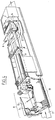
- fig. 4 shows a partly broken away perspective view of such a device.
- a device comprises a housing 12 inside which two layers of nozzles 13 are arranged and inside which fans are arranged to maintain a circulation within separate units inside the drier.
- a drier in which however the invention is not applied, is otherwise described more extensively in the Dutch patent application number 8902825, to which reference is made.
- a burner 3 In the housing of the drier is further arranged a burner 3, while recirculation duct 9 debouches into the space where burner 3 is present.
- the other side of recirculation duct 9 is connected to a valve housing 14 in which is arranged a three-way valve 11. Further shown in this drawing is the outlet duct 8 for gas for discharging.
Landscapes
- Engineering & Computer Science (AREA)
- Mechanical Engineering (AREA)
- General Engineering & Computer Science (AREA)
- Textile Engineering (AREA)
- Drying Of Solid Materials (AREA)
- Supply, Installation And Extraction Of Printed Sheets Or Plates (AREA)
Claims (9)
- Verfahren zum Trocknen von bedruckten Streifen in einem Trockner, der ein Gehäuse umfaßt, durch das die bedruckten Streifen bewegt werden, eine Einrichtung zum Stützen des Streifens, eine Einrichtung zum Zuführen von Heißluft in das Gehäuse, eine Einrichtung zum Ableiten von Gas aus dem Gehäuse und eine Umlufteinrichtung, die derart gestaltet ist, daß eine Zirkulation parallel zur Bewegungsrichtung des Streifens aufrechterhalten wird, wobei beim Stillstand des bedruckten Streifens (2) das Zirkulationssystem (9, 10) dem Trockner (1) heiße Gase entzieht und diese Gase an einer anderen Stelle dem Trockner (1) wieder zuführt und somit die Zirkulation der heißen Gase im Trockner (1) aufrechterhalten wird.
- Verfahren nach Anspruch 1,
dadurch gekennzeichnet,
daß das Zirkulationssystem (9, 10) ein Rohr umfaßt, das sich von der einen Seite zur gegenüberliegenden Seite des Gehäuses (12) erstreckt. - Verfahren nach Anspruch 1 oder 2,
dadurch gekennzeichnet,
daß die Zuführeinrichtung (5, 6) und die Ablaßeinrichtung (7, 8) derart angeordnet sind, daß die Flußrichtung des Gases während des normalen Betriebs die gleiche ist, wie die Bewegungsrichtung des Streifens (2). - Verfahren nach einem der vorangehenden Ansprüche,
dadurch gekennzeichnet,
daß die Zuführeinrichtung (5, 6) mit dem Brenner (3) verbunden ist. - Verfahren nach Anspruch 4,
dadurch gekennzeichnet,
daß der Brenner (3) in dem Gehäuse (12) angeordnet ist. - Verfahren nach einem der Ansprüche 1-5,
dadurch gekennzeichnet,
daß das Zirkulationssystem (9, 10) ein Rohr umfaßt, das sich von der Ablaßeinrichtung zur Zuführeinrichtung erstreckt, und das mit mindestens einem Ventil (11) ausgerüstet ist. - Verfahren nach Anspruch 6,
dadurch gekennzeichnet,
daß das Ventil (11) ein Dreiwegventil ist, das an der Ablaßeinrichtung (7, 8) angeordnet ist. - Verfahren nach Anspruch 4,
dadurch gekennzeichnet,
daß der Brenner (3) mit einem Luftzuführrohr (6) verbunden ist, in welchem ein Ventil angeordnet ist, das während eines Stillstands des Trockners (1) zum Teil geöffnet ist, um dem Brenner (3) Luft zuzuführen. - Verfahren nach einem der Ansprüche 2-7,
dadurch gekennzeichnet,
daß in dem Umluftrohr (9) ein Gebläse angeordnet ist.
Applications Claiming Priority (2)
| Application Number | Priority Date | Filing Date | Title |
|---|---|---|---|
| NL9300199 | 1993-02-01 | ||
| NL9300199A NL9300199A (nl) | 1993-02-01 | 1993-02-01 | Droger met verkorte heropstart. |
Publications (2)
| Publication Number | Publication Date |
|---|---|
| EP0609938A1 EP0609938A1 (de) | 1994-08-10 |
| EP0609938B1 true EP0609938B1 (de) | 1999-05-06 |
Family
ID=19862006
Family Applications (1)
| Application Number | Title | Priority Date | Filing Date |
|---|---|---|---|
| EP94200172A Expired - Lifetime EP0609938B1 (de) | 1993-02-01 | 1994-01-26 | Verfahren zum Trocknen bedruckter Streifen |
Country Status (5)
| Country | Link |
|---|---|
| US (1) | US5584131A (de) |
| EP (1) | EP0609938B1 (de) |
| JP (1) | JP3474617B2 (de) |
| DE (1) | DE69418226T2 (de) |
| NL (1) | NL9300199A (de) |
Cited By (1)
| Publication number | Priority date | Publication date | Assignee | Title |
|---|---|---|---|---|
| US10006712B2 (en) | 2014-10-06 | 2018-06-26 | Westmill Industries Ltd. | Recirculating system for use with green wood veneer dryers and method for drying green wood veneer |
Families Citing this family (4)
| Publication number | Priority date | Publication date | Assignee | Title |
|---|---|---|---|---|
| US5555635A (en) * | 1995-01-18 | 1996-09-17 | W. R. Grace & Co.-Conn. | Control and arrangement of a continuous process for an industrial dryer |
| DE19713529A1 (de) * | 1997-04-01 | 1998-10-08 | Heidelberger Druckmasch Ag | Trockner für eine Materialbahn mit Abgasezirkulation |
| SG11201709802XA (en) * | 2015-06-03 | 2017-12-28 | Kuraray Co | Method for producing conjugated diene |
| CN107953667A (zh) * | 2017-11-29 | 2018-04-24 | 江苏飞视文化发展有限公司 | 一种广告打印纸张油墨快速风干的方法 |
Family Cites Families (13)
| Publication number | Priority date | Publication date | Assignee | Title |
|---|---|---|---|---|
| US3882612A (en) * | 1973-07-27 | 1975-05-13 | Moore Dry Kiln Co | Method and apparatus for limiting the concentration of combustible volatiles in dryer emissions |
| FR2312702A1 (fr) * | 1975-05-29 | 1976-12-24 | Mcv | Vanne pour la substitution a volonte d'un fluide gazeux a un autre fluide gazeux dans un circuit ferme |
| ATE24606T1 (de) * | 1981-05-25 | 1987-01-15 | Meg Materiels Equip Graphiques | Vorrichtung zum trocknen von bahnen durch heissluft bei gleichzeitiger unterstuetzung der bahn, vorzugsweise von papierbahnen aus druckmaschinen. |
| JPS58175662A (ja) * | 1982-04-09 | 1983-10-14 | Toshiba Mach Co Ltd | 印刷機の脱臭装置付き乾燥炉 |
| DE3312226A1 (de) * | 1983-04-05 | 1984-10-11 | Babcock Textilmaschinen GmbH, 2105 Seevetal | Anordnung zur waermebehandlung laufender warenbahnen |
| DE3336331C2 (de) * | 1983-10-06 | 1985-12-05 | A. Monforts GmbH & Co, 4050 Mönchengladbach | Konvektionstrocken- und/oder -fixiermaschine |
| DE3419531A1 (de) * | 1984-05-25 | 1985-11-28 | Babcock Textilmaschinen GmbH, 2105 Seevetal | Anordnung zur vermeidung der beschaedigung von warenbahnen bei der trockenwaermebehandlung mittels stroemender behandlungsmittel |
| DE3535421A1 (de) * | 1985-10-04 | 1987-04-16 | Krantz H Gmbh & Co | Vorrichtung zur waermebehandlung einer warenbahn |
| DE3627904A1 (de) * | 1986-08-16 | 1988-02-18 | Monforts Gmbh & Co A | Konvektionstrocken- und/oder -fixiermaschine |
| DE3727280A1 (de) * | 1987-08-16 | 1989-03-02 | Brueckner Trockentechnik Gmbh | Vorrichtung zur waermebehandlung einer warenbahn |
| NL8800226A (nl) * | 1988-01-29 | 1989-08-16 | Stork Contiweb | Droger voor een materiaalbaan. |
| US5022167A (en) * | 1988-09-05 | 1991-06-11 | Fuji Photo Film Co., Ltd. | Photosensitive material drying apparatus |
| DE4033637A1 (de) * | 1990-10-23 | 1992-04-30 | Babcock Textilmasch | Vorrichtung zur umluftmengenregelung bei waermebehandlungsvorrichtungen, wie trocknern und dgl. |
-
1993
- 1993-02-01 NL NL9300199A patent/NL9300199A/nl not_active Application Discontinuation
-
1994
- 1994-01-26 DE DE69418226T patent/DE69418226T2/de not_active Expired - Lifetime
- 1994-01-26 US US08/186,514 patent/US5584131A/en not_active Expired - Lifetime
- 1994-01-26 EP EP94200172A patent/EP0609938B1/de not_active Expired - Lifetime
- 1994-01-28 JP JP00823494A patent/JP3474617B2/ja not_active Expired - Fee Related
Cited By (1)
| Publication number | Priority date | Publication date | Assignee | Title |
|---|---|---|---|---|
| US10006712B2 (en) | 2014-10-06 | 2018-06-26 | Westmill Industries Ltd. | Recirculating system for use with green wood veneer dryers and method for drying green wood veneer |
Also Published As
| Publication number | Publication date |
|---|---|
| JP3474617B2 (ja) | 2003-12-08 |
| US5584131A (en) | 1996-12-17 |
| EP0609938A1 (de) | 1994-08-10 |
| JPH071714A (ja) | 1995-01-06 |
| NL9300199A (nl) | 1994-09-01 |
| DE69418226D1 (de) | 1999-06-10 |
| DE69418226T2 (de) | 1999-09-30 |
Similar Documents
| Publication | Publication Date | Title |
|---|---|---|
| KR880001525B1 (ko) | 종이웨브 건조장치 및 방법 | |
| US4936025A (en) | Combination infrared and airborne drying of a web | |
| FI82961B (fi) | Anordning foer att aotervinna vaerme i avluften fraon en pappersmaskins tork. | |
| US7316080B1 (en) | Methodology and apparatus to reduce fuel consumption in conveyor dryers and ovens | |
| EP1044813B1 (de) | Trockner für Flexo- und Tiefdruck | |
| CA2145573C (en) | Apparatus and method for treating a sheet of material | |
| US5465504A (en) | System for modifying the moisture profile of a paper web | |
| KR840005208A (ko) | 회전 건조기를 열응력으로 부터 보호하는 장치 | |
| US6869506B2 (en) | Apparatus for dewatering a paper web and associated system and method | |
| WO1988009845A1 (en) | Method in the drying of a paper web or equivalent | |
| EP0609938B1 (de) | Verfahren zum Trocknen bedruckter Streifen | |
| US5784804A (en) | Yankee hood with integral air heating system | |
| WO1998033973A1 (en) | Pocket ventilation and sheet support system in a papermaking machine dryer section | |
| JPH0315552A (ja) | ドライヤから出る材料ウェブの冷却装置 | |
| US4523390A (en) | Peripheral exhaust system for high velocity dryer | |
| JP2000211111A (ja) | 巻取紙をシ―ズニングする装置 | |
| JP3787093B2 (ja) | 乾燥部において排出空気および供給空気を設定する方法および装置 | |
| US6058626A (en) | Dryer for a material web with exhaust gas recirculation | |
| JP2000211205A (ja) | 乾燥した巻取紙を再加湿する装置 | |
| WO2000063628A1 (en) | Infrared dryer with air purge shutter | |
| US6412190B1 (en) | Infrared and hot air dryer combination | |
| US4457087A (en) | Steam trough mangle with heat recycling apparatus | |
| US3328895A (en) | Web dryer | |
| US6332279B1 (en) | Drying device | |
| US5228210A (en) | Method of and apparatus for drying for film developing device |
Legal Events
| Date | Code | Title | Description |
|---|---|---|---|
| PUAI | Public reference made under article 153(3) epc to a published international application that has entered the european phase |
Free format text: ORIGINAL CODE: 0009012 |
|
| AK | Designated contracting states |
Kind code of ref document: A1 Designated state(s): DE FR GB IT NL SE |
|
| 17P | Request for examination filed |
Effective date: 19950113 |
|
| RAP1 | Party data changed (applicant data changed or rights of an application transferred) |
Owner name: HEIDELBERG CONTIWEB B.V. |
|
| 17Q | First examination report despatched |
Effective date: 19970402 |
|
| GRAG | Despatch of communication of intention to grant |
Free format text: ORIGINAL CODE: EPIDOS AGRA |
|
| GRAG | Despatch of communication of intention to grant |
Free format text: ORIGINAL CODE: EPIDOS AGRA |
|
| GRAH | Despatch of communication of intention to grant a patent |
Free format text: ORIGINAL CODE: EPIDOS IGRA |
|
| GRAH | Despatch of communication of intention to grant a patent |
Free format text: ORIGINAL CODE: EPIDOS IGRA |
|
| GRAA | (expected) grant |
Free format text: ORIGINAL CODE: 0009210 |
|
| RAP1 | Party data changed (applicant data changed or rights of an application transferred) |
Owner name: HEIDELBERGER DRUCKMASCHINEN AKTIENGESELLSCHAFT |
|
| AK | Designated contracting states |
Kind code of ref document: B1 Designated state(s): DE FR GB IT NL SE |
|
| PG25 | Lapsed in a contracting state [announced via postgrant information from national office to epo] |
Ref country code: SE Free format text: THE PATENT HAS BEEN ANNULLED BY A DECISION OF A NATIONAL AUTHORITY Effective date: 19990506 Ref country code: IT Free format text: LAPSE BECAUSE OF FAILURE TO SUBMIT A TRANSLATION OF THE DESCRIPTION OR TO PAY THE FEE WITHIN THE PRE;WARNING: LAPSES OF ITALIAN PATENTS WITH EFFECTIVE DATE BEFORE 2007 MAY HAVE OCCURRED AT ANY TIME BEFORE 2007. THE CORRECT EFFECTIVE DATE MAY BE DIFFERENT FROM THE ONE RECORDED.SCRIBED TIME-LIMIT Effective date: 19990506 |
|
| REF | Corresponds to: |
Ref document number: 69418226 Country of ref document: DE Date of ref document: 19990610 |
|
| ET | Fr: translation filed | ||
| PLBE | No opposition filed within time limit |
Free format text: ORIGINAL CODE: 0009261 |
|
| STAA | Information on the status of an ep patent application or granted ep patent |
Free format text: STATUS: NO OPPOSITION FILED WITHIN TIME LIMIT |
|
| 26N | No opposition filed | ||
| REG | Reference to a national code |
Ref country code: GB Ref legal event code: IF02 |
|
| PGFP | Annual fee paid to national office [announced via postgrant information from national office to epo] |
Ref country code: GB Payment date: 20021224 Year of fee payment: 10 |
|
| PGFP | Annual fee paid to national office [announced via postgrant information from national office to epo] |
Ref country code: NL Payment date: 20030121 Year of fee payment: 10 |
|
| PG25 | Lapsed in a contracting state [announced via postgrant information from national office to epo] |
Ref country code: GB Free format text: LAPSE BECAUSE OF NON-PAYMENT OF DUE FEES Effective date: 20040126 |
|
| PG25 | Lapsed in a contracting state [announced via postgrant information from national office to epo] |
Ref country code: NL Free format text: LAPSE BECAUSE OF NON-PAYMENT OF DUE FEES Effective date: 20040801 |
|
| GBPC | Gb: european patent ceased through non-payment of renewal fee |
Effective date: 20040126 |
|
| NLV4 | Nl: lapsed or anulled due to non-payment of the annual fee |
Effective date: 20040801 |
|
| PGFP | Annual fee paid to national office [announced via postgrant information from national office to epo] |
Ref country code: FR Payment date: 20100205 Year of fee payment: 17 |
|
| PGFP | Annual fee paid to national office [announced via postgrant information from national office to epo] |
Ref country code: DE Payment date: 20100127 Year of fee payment: 17 |
|
| REG | Reference to a national code |
Ref country code: FR Ref legal event code: ST Effective date: 20110930 |
|
| PG25 | Lapsed in a contracting state [announced via postgrant information from national office to epo] |
Ref country code: FR Free format text: LAPSE BECAUSE OF NON-PAYMENT OF DUE FEES Effective date: 20110131 |
|
| REG | Reference to a national code |
Ref country code: DE Ref legal event code: R119 Ref document number: 69418226 Country of ref document: DE Effective date: 20110802 |
|
| PG25 | Lapsed in a contracting state [announced via postgrant information from national office to epo] |
Ref country code: DE Free format text: LAPSE BECAUSE OF NON-PAYMENT OF DUE FEES Effective date: 20110802 |