EP0610558A1 - Dispositif d'ouverture et de fermeture d'un battant - Google Patents
Dispositif d'ouverture et de fermeture d'un battant Download PDFInfo
- Publication number
- EP0610558A1 EP0610558A1 EP93118521A EP93118521A EP0610558A1 EP 0610558 A1 EP0610558 A1 EP 0610558A1 EP 93118521 A EP93118521 A EP 93118521A EP 93118521 A EP93118521 A EP 93118521A EP 0610558 A1 EP0610558 A1 EP 0610558A1
- Authority
- EP
- European Patent Office
- Prior art keywords
- fastening
- swivel arm
- fastening device
- length
- fastening devices
- Prior art date
- Legal status (The legal status is an assumption and is not a legal conclusion. Google has not performed a legal analysis and makes no representation as to the accuracy of the status listed.)
- Granted
Links
- 238000000605 extraction Methods 0.000 claims abstract description 9
- 239000000779 smoke Substances 0.000 claims description 29
- 239000002390 adhesive tape Substances 0.000 claims 1
- 230000037431 insertion Effects 0.000 claims 1
- 238000003780 insertion Methods 0.000 claims 1
- 230000008878 coupling Effects 0.000 abstract 1
- 238000010168 coupling process Methods 0.000 abstract 1
- 238000005859 coupling reaction Methods 0.000 abstract 1
- 230000013011 mating Effects 0.000 abstract 1
- 238000013016 damping Methods 0.000 description 20
- 238000009423 ventilation Methods 0.000 description 4
- 238000009434 installation Methods 0.000 description 2
- 239000012530 fluid Substances 0.000 description 1
- 239000003517 fume Substances 0.000 description 1
- 238000000034 method Methods 0.000 description 1
- 238000003801 milling Methods 0.000 description 1
- 230000000414 obstructive effect Effects 0.000 description 1
- 238000004806 packaging method and process Methods 0.000 description 1
Images











Classifications
-
- F—MECHANICAL ENGINEERING; LIGHTING; HEATING; WEAPONS; BLASTING
- F24—HEATING; RANGES; VENTILATING
- F24F—AIR-CONDITIONING; AIR-HUMIDIFICATION; VENTILATION; USE OF AIR CURRENTS FOR SCREENING
- F24F7/00—Ventilation
- F24F7/02—Roof ventilation
-
- E—FIXED CONSTRUCTIONS
- E04—BUILDING
- E04D—ROOF COVERINGS; SKY-LIGHTS; GUTTERS; ROOF-WORKING TOOLS
- E04D13/00—Special arrangements or devices in connection with roof coverings; Protection against birds; Roof drainage ; Sky-lights
- E04D13/03—Sky-lights; Domes; Ventilating sky-lights
- E04D13/035—Sky-lights; Domes; Ventilating sky-lights characterised by having movable parts
- E04D13/0351—Sky-lights; Domes; Ventilating sky-lights characterised by having movable parts the parts pivoting about a fixed axis
- E04D13/0352—Sky-lights; Domes; Ventilating sky-lights characterised by having movable parts the parts pivoting about a fixed axis the parts being of domed or pyramidal shape
-
- E—FIXED CONSTRUCTIONS
- E05—LOCKS; KEYS; WINDOW OR DOOR FITTINGS; SAFES
- E05F—DEVICES FOR MOVING WINGS INTO OPEN OR CLOSED POSITION; CHECKS FOR WINGS; WING FITTINGS NOT OTHERWISE PROVIDED FOR, CONCERNED WITH THE FUNCTIONING OF THE WING
- E05F15/00—Power-operated mechanisms for wings
- E05F15/50—Power-operated mechanisms for wings using fluid-pressure actuators
- E05F15/53—Power-operated mechanisms for wings using fluid-pressure actuators for swinging wings
-
- E—FIXED CONSTRUCTIONS
- E05—LOCKS; KEYS; WINDOW OR DOOR FITTINGS; SAFES
- E05F—DEVICES FOR MOVING WINGS INTO OPEN OR CLOSED POSITION; CHECKS FOR WINGS; WING FITTINGS NOT OTHERWISE PROVIDED FOR, CONCERNED WITH THE FUNCTIONING OF THE WING
- E05F1/00—Closers or openers for wings, not otherwise provided for in this subclass
- E05F1/08—Closers or openers for wings, not otherwise provided for in this subclass spring-actuated, e.g. for horizontally sliding wings
- E05F1/10—Closers or openers for wings, not otherwise provided for in this subclass spring-actuated, e.g. for horizontally sliding wings for swinging wings, e.g. counterbalance
-
- E—FIXED CONSTRUCTIONS
- E05—LOCKS; KEYS; WINDOW OR DOOR FITTINGS; SAFES
- E05Y—INDEXING SCHEME ASSOCIATED WITH SUBCLASSES E05D AND E05F, RELATING TO CONSTRUCTION ELEMENTS, ELECTRIC CONTROL, POWER SUPPLY, POWER SIGNAL OR TRANSMISSION, USER INTERFACES, MOUNTING OR COUPLING, DETAILS, ACCESSORIES, AUXILIARY OPERATIONS NOT OTHERWISE PROVIDED FOR, APPLICATION THEREOF
- E05Y2900/00—Application of doors, windows, wings or fittings thereof
- E05Y2900/10—Application of doors, windows, wings or fittings thereof for buildings or parts thereof
- E05Y2900/13—Type of wing
- E05Y2900/148—Windows
- E05Y2900/152—Roof windows
- E05Y2900/154—Skylights
Definitions
- the invention relates to a device for opening and closing a flap pivotally mounted on one side of a frame of the type specified in the preamble of claim 1.
- Such devices are main components of smoke and heat extraction systems and serve to close the flaps, e.g. Skylights or skylights integrated in skylights, which cannot be opened manually, can be opened and closed hydraulically, pneumatically or electromotively if necessary. Normally, this creates ventilation for the room in question; In the event of a fire, an automatically releasable smoke and heat vent can be provided with such a system.
- the German utility model G 8 808 856 describes a smoke vent and ventilation flap with a device for opening and closing a roof flap. Another smoke and heat extraction device is known from utility model G 8 124 554, an opening angle of over 90 ° being achieved for one or more skylight domes.
- the utility model G 8 006 402 has a device for opening and closing a smoke and heat flap to the subject.
- a specially designed lifting cylinder is described in detail, which is particularly suitable for emergency opening of the flap.
- the device according to the above-mentioned patent is in the assembled and closed state a very bulky unit and, because the three pivot elements are connected at a point that lies far below the surface formed by the underside of the frame, can only be transported individually. Since this type of transport is very complex and expensive, such systems are usually delivered to the destination, unassembled or partially assembled, where the final assembly then takes place. The disadvantages arising from this are high assembly costs at the destination, difficult assembly conditions at the destination, additional safety measures required during assembly and additional costs for packaging, storage and shipping of obstructive components. When the bulky complete system is delivered in single transport, there are high transport costs to the destination.
- the object of the present invention is to provide a device for opening and closing a flap of the specified type, which makes it possible to stack several fume cupboards with already installed, functionally tested opening and closing devices for transport without having to make large installation efforts at the destination or the above-mentioned disadvantages regarding transport in the disassembled state occur.
- Both the lifting cylinder and the swivel arm together with their fastening devices form one-piece units, so that no further individual parts are required for the final assembly. If the connection between the lifting cylinder and swivel arm is released, the opening and closing device already assembled with the flap can be folded into the space under the flap without further disassembly and held together with simple aids, such as cable ties, so that it is possible to complete several Stacking systems for transport on top of each other and delivering them completely and compactly to their destination. There, the transport lock can be easily released and the opening and closing device can be assembled in a few simple steps by connecting the two fastening devices.
- the fixed but detachable connection of the two fastening devices of the lifting cylinder and the swivel arm can be made in different variants.
- Some examples of this are a bayonet lock, a threaded lock, a locking disc lock, a snap lock and a slot lock.
- the present invention has the following advantages over the prior art: At the place of final assembly of the smoke and heat exhaust system, screwing work is no longer necessary, since only the transport lock has to be released and the lifting cylinder has to be locked. Safety devices, such as nets against falling Parts can be omitted due to the use of mechanically secured components. An opening and closing device that has already been functionally tested at the factory no longer has to be dismantled for transport. The lines and connections for the supply of working fluids are not disconnected after the first installation. At the final assembly site, no individual parts can be missing and no construction-like parts of other devices can be confused with those belonging to the opening and closing device. The assembly personnel can work from a secured position during final assembly and do not have to operate over the open roof cutout of the room.
- the lifting cylinder decoupled for transport can be used again without the use of tools.
- An assembly hook-on scaffold is no longer necessary for oversized smoke and heat exhaust ventilators.
- a single function test of the device assembled in the factory can be omitted after the final assembly on site because the important parts no longer have to be dismantled for transport.
- the complete smoke and heat exhaust ventilation systems pre-assembled and secured for transport can be stacked in groups of several. The transport costs per unit can thus be reduced to a minimum.
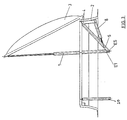
- Figure 1 shows the smoke and heat exhaust system in the closed state.
- a roof opening Frame 2 attached.
- a strut 9 is provided, on which a bracket 4 is attached.
- a swivel arm 5 is articulated on the strut 9.
- a damping element 8 is articulated at the lower end of the console 4.
- the extension part of the damping element 8 is articulated to the swivel arm 5.
- the free end E5 of the swivel arm 5 is fixed, but articulated, to the end E1 of a lifting cylinder 1 by the fastening devices 6 and 7, shown in detail Y.
- the other end of the lifting cylinder 1 is articulated on the side of a flap 3 opposite the articulation side of the frame 2.
- Extending the lifting cylinder 1 causes a pivoting movement of the flap 3 around its articulation point on the frame 2 in a clockwise direction, which corresponds to an opening of the smoke and heat exhaust system.
- the swivel arm 5 and a damping cylinder 8 have the purpose of balancing the mechanically generated forces at the connection point of the fastening devices 6 and 7 and of holding the opening and closing device in the desired opening position.
- the smoke and heat exhaust system in its partially open position is shown in Fig. 3.
- the lifting cylinder 1 is extended into its longest position and the flap 3 is opened to extract smoke and / or warm air from the interior of the room.
- the swivel arm 5 and the damping element 8 hold the opening and closing device in the desired opening position.
- FIG. 2 A smoke and heat extraction device prepared for transport is shown in FIG. 2.
- the fastening devices 6 and 7 are detached from one another, ie, the lifting cylinder 1 and the swivel arm 5 in connection with the damping element 8 can be easily folded into the space under the flap 3.
- they are tied together with simple connecting means, such as cable ties.
- the damping element 8 is in a fully extended position, the lifting cylinder 1 reaching its shortest length.
- Figure 13 shows two stacked smoke and heat exhaust systems, it being apparent that the parts of the upper device for opening and closing a smoke and heat flap do not come into contact with the flap of the lower system.
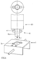
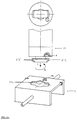
- FIG. 4 shows an enlarged perspective view of the two fastening devices 6 and 7 in the embodiment with a bayonet lock, the cam 64 'having bayonet foot 64, which is located at the free end E1, in the direction of arrow I in a shaped as a counterpart to the bayonet foot and as a shaped hole pronounced recess 74 of the U-shaped, pivotable fastening device 7 is pushed and is rotated for fixing in the direction of arrow II, whereby the cams 64 'slide behind the edge of the recess and thus lock the bayonet foot.
- Fig. 5 shows an enlarged perspective view of the two fastening devices 6 and 7 in a Ausrete tion, in which a chamfered countersunk 65 is inserted at the free end E1 in an opening receiving the countersunk 65 (arrow).
- a lock washer 75 attached to the Opening of the pivotable, U-shaped fastening device 7 is attached, the fixed connection of the countersunk bolt 6 with the fastening device 7.
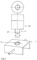
- FIG. 6 shows an enlarged perspective view of the two fastening devices 6 and 7 in the embodiment in which a threaded rod 76 is attached to the pivotable, U-shaped fastening device 7 of the lifting cylinder 1.
- the end E1 of the lifting cylinder 1 has a fastening device 6, which is rotatably mounted about its longitudinal axis and has an internal thread 66, which is screwed onto the threaded rod 76 in order to connect the fastening devices 6 and 7.
- Fig. 7 shows an enlarged perspective view of the fastening devices 6 and 7 in the embodiment in which a threaded rod 67 is attached to the fastening device 6 of the lifting cylinder 1, the screwing of the threaded rod 67 into an internal thread 77, which in the pivotable U-shaped Fastening device 7 is cut in the connection.
- FIG. 8 shows an enlarged perspective view of the fastening devices 6 and 7 in the embodiment in which a spring clip 78 is attached to the pivotable U-shaped fastening device 7 under an opening 78 ′.
- a stepped retaining bolt 68 is provided, which connects the fastening devices 6 and 7 by snapping (in the direction of the arrow) into the spring clip 78.
- FIG. 9 shows an enlarged perspective view of the fastening devices 6 and 7 in the embodiment in which a spring clamp 79 under a slot 79 ′ on the pivotable U-shaped fastening device 7 is appropriate.
- a stepped fastening bolt 69 which, by snapping (in the direction of the arrow) into the spring clamp 79, establishes the connection of the fastening devices 6 and 7.
- FIG. 10 shows an enlarged perspective view of the fastening devices 6 and 7 in the embodiment in which two snap jaws 710 are attached to the pivotable U-shaped fastening device 7 under an opening 710 ′.
- a stepped retaining bolt 610 which, by snapping (in the direction of the arrow) into the snap jaws 710, establishes the connection of the fastening devices 6 and 7.
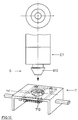
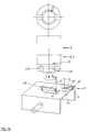
- Fig. 11 shows an enlarged perspective view of the fastening devices 6 and 7 in the embodiment in which a stepped, rotatably mounted holding bolt 611, which is provided with a lateral milling, at the end E1 of the lifting cylinder 1 on the fastening device 6 first in the direction of arrow I in a larger hole 711 'of the pivotable U-shaped fastening device 7, then in the direction of arrow II in a smaller hole 711' ', which is connected to the larger hole 711', and finally secured by turning in the direction of arrow III and locking a guide rod F. , wherein a projection V at the end of the guide rod F engages in the locking hole R in the fastening device 7.
- FIG. 12 shows an enlarged perspective view of the two fastening devices 6 and 7 in the embodiment with a snap-in bayonet lock, the bayonet foot 612, which is located at the free end E1, in the direction of arrow I into a recess 712 shaped as a counterpart to the bayonet foot and shaped as a shaped hole the U-shaped, pivotable fastening device 7 is pushed and is to be rotated in the direction of arrow II for fixing, whereby the protruding ends of the bayonet base 612 'slide behind the edge of the recess and thus lock the bayonet base; this causes a recess A to lie in the lower surface of the free end E1 above a spring holding device FH, which then engages in the recess.
- FIG. 14 shows the smoke and heat extraction system in a configuration in which the damping element 8 is attached to the side on the swivel arm 5, from which a moving part of the damping element also extends, and is articulated on the console 4.
- This embodiment is highly space-saving.
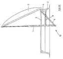
- Figure 15 shows an embodiment of the smoke and heat exhaust system, in which no console is provided for fastening the damping element 8 and the swivel arm 5. Both parts 5, 8 are fastened here to the strut 9, which is attached to the inside of the frame. The point at which the damping element 8 is articulated on the swivel arm 5 is located between the articulation point of the swivel arm 5 on the strut 9 and the connection point of the lifting cylinder 1 with the swivel arm 5.
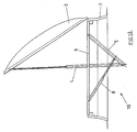
- FIG. 16 also describes an embodiment in which the swivel arm 5 and the damping element 8 are fastened to the strut 9.
- the damping element 8 is articulated with its free end, namely its outer piston, to the outer end of the swivel arm 5, the articulation point of the swivel arm 5 and lifting cylinder 1 coinciding with the articulation point of the swivel arm 5 on the damping element 8.
- Figure 17 shows an embodiment of the smoke and heat exhaust system, in which no damping element is provided, but the swivel arm 5 can be locked to the frame 2 by a locking web 11 attached to it.
- FIG. 18 shows an enlarged perspective view of the two easily mountable fastening devices 6 and 7 in the embodiment with a snap-in bayonet lock and locking spring AF.
- a downwardly open radial bore B lies on the underside of the free end E1 over an upwardly projecting snap-in extension EF of the locking spring AF, which then engages in the bore B.
- the locking spring AF is fastened between the outer edge of the upper surface of the fastening device 7 and the edge of the counterpart 718 to the bayonet foot 618.
- the locking spring AF is formed like a clamp and has at one end the snap-in extension EF which is angled substantially perpendicularly to a central spring clip FB, while at its other end it has a holding extension HF which is bent back essentially parallel to the spring clip FB and has an angled snap-in end EE.
- the snap-in extension EF of the locking spring AF is, when it is fastened to the fastening device 7, in the Retaining notch HI is clamped in the counterpart 718 to the bayonet foot 618 in such a way that the snap-in extension EF projects upward beyond the upper surface of the fastening device 7, while the bent-back retaining extension HF is clamped with its arch into the outer retaining notch HA, the angled snap-in end EE for further
- the spring AF bracket snaps into the elongated hole LL.
- Figure 19 shows a sectional view of the two assembled fastening devices from Figure 18 to illustrate the release process of the locking spring AF.
- a screwdriver presses through a round hole extension LF provided on the elongated hole LL from above onto the lower part of the locking spring AF, as a result of which the upwardly projecting part of the spring detaches from the bore B and releases the bayonet foot 618 for unscrewing.
- Figures 1, 2, 3 and 13 show on the side of the strut 9, which lies opposite the articulation side of the flap 3, an opening unit 20 articulated there for daily ventilation, which can also be used to open the flap.
- This opening unit 20 can easily be folded into the space under the flap 3 for transport like the other individual parts and secured with the aids mentioned above.
Landscapes
- Engineering & Computer Science (AREA)
- Chemical & Material Sciences (AREA)
- Combustion & Propulsion (AREA)
- Mechanical Engineering (AREA)
- General Engineering & Computer Science (AREA)
- Architecture (AREA)
- Civil Engineering (AREA)
- Structural Engineering (AREA)
- Clamps And Clips (AREA)
- Air-Flow Control Members (AREA)
- Power-Operated Mechanisms For Wings (AREA)
Applications Claiming Priority (2)
| Application Number | Priority Date | Filing Date | Title |
|---|---|---|---|
| DE4303767 | 1993-02-09 | ||
| DE4303767A DE4303767C1 (de) | 1993-02-09 | 1993-02-09 | Vorrichtung zum Öffnen und Schließen einer Klappe |
Publications (2)
| Publication Number | Publication Date |
|---|---|
| EP0610558A1 true EP0610558A1 (fr) | 1994-08-17 |
| EP0610558B1 EP0610558B1 (fr) | 1996-08-14 |
Family
ID=6480000
Family Applications (1)
| Application Number | Title | Priority Date | Filing Date |
|---|---|---|---|
| EP93118521A Expired - Lifetime EP0610558B1 (fr) | 1993-02-09 | 1993-11-16 | Dispositif d'ouverture et de fermeture d'un battant |
Country Status (3)
| Country | Link |
|---|---|
| EP (1) | EP0610558B1 (fr) |
| AT (1) | ATE141380T1 (fr) |
| DE (2) | DE4303767C1 (fr) |
Cited By (2)
| Publication number | Priority date | Publication date | Assignee | Title |
|---|---|---|---|---|
| EP1548220A1 (fr) | 2003-12-22 | 2005-06-29 | Poul Erik Halkjaer | Commande pour lanternau |
| CN114352150A (zh) * | 2021-12-07 | 2022-04-15 | 中国建筑标准设计研究院有限公司 | 一种多扇对称折叠式防护密闭门结构 |
Families Citing this family (3)
| Publication number | Priority date | Publication date | Assignee | Title |
|---|---|---|---|---|
| DE4403554A1 (de) * | 1994-02-04 | 1995-08-10 | Kloeckner Humboldt Deutz Ag | Dachluke |
| ITCT20000025A1 (it) * | 2000-10-13 | 2002-04-13 | Domenico Platania | Braccio automatico e manuale per l'apertura e chiusura di cancelli. |
| DE10324444B4 (de) * | 2003-05-28 | 2007-02-15 | Heinrich Strunz Gmbh | Montagevorrichtung |
Citations (2)
| Publication number | Priority date | Publication date | Assignee | Title |
|---|---|---|---|---|
| DE3338092A1 (de) * | 1983-10-20 | 1985-05-02 | Fa. J. Eberspächer, 7300 Esslingen | Vorrichtung zum rauch- und waermeabzug sowie zum be- und entlueften von geschlossenen raeumen |
| EP0291376A1 (fr) * | 1987-05-05 | 1988-11-17 | Societe Industrielle Du Haras Societe Anonyme Dite: | Mécanisme de manoeuvre de la coupole d'un exutoire de fumée |
Family Cites Families (3)
| Publication number | Priority date | Publication date | Assignee | Title |
|---|---|---|---|---|
| DE8006402U1 (de) * | 1980-03-08 | 1983-03-31 | Heinz Essmann Gmbh & Co Kg, 4902 Bad Salzuflen | Vorrichtung zum oeffnen und schliessen einer rauch- und waermeabzugsklappe |
| DE8124554U1 (de) * | 1981-08-22 | 1981-12-17 | Heinz Essmann GmbH & Co KG, 4904 Bad Salzuflen | Rauch- und waermeabzugsvorrichtung |
| DE8808856U1 (de) * | 1988-07-09 | 1988-08-25 | Grescha-Gesellschaft mbH & Co Grefe & Scharf, 4817 Leopoldshöhe | Rauchabzugs- und Lüftungsklappe |
-
1993
- 1993-02-09 DE DE4303767A patent/DE4303767C1/de not_active Expired - Fee Related
- 1993-11-16 AT AT93118521T patent/ATE141380T1/de not_active IP Right Cessation
- 1993-11-16 EP EP93118521A patent/EP0610558B1/fr not_active Expired - Lifetime
- 1993-11-16 DE DE59303440T patent/DE59303440D1/de not_active Expired - Fee Related
Patent Citations (2)
| Publication number | Priority date | Publication date | Assignee | Title |
|---|---|---|---|---|
| DE3338092A1 (de) * | 1983-10-20 | 1985-05-02 | Fa. J. Eberspächer, 7300 Esslingen | Vorrichtung zum rauch- und waermeabzug sowie zum be- und entlueften von geschlossenen raeumen |
| EP0291376A1 (fr) * | 1987-05-05 | 1988-11-17 | Societe Industrielle Du Haras Societe Anonyme Dite: | Mécanisme de manoeuvre de la coupole d'un exutoire de fumée |
Cited By (3)
| Publication number | Priority date | Publication date | Assignee | Title |
|---|---|---|---|---|
| EP1548220A1 (fr) | 2003-12-22 | 2005-06-29 | Poul Erik Halkjaer | Commande pour lanternau |
| CN114352150A (zh) * | 2021-12-07 | 2022-04-15 | 中国建筑标准设计研究院有限公司 | 一种多扇对称折叠式防护密闭门结构 |
| CN114352150B (zh) * | 2021-12-07 | 2023-11-17 | 中国建筑标准设计研究院有限公司 | 一种多扇对称折叠式防护密闭门结构 |
Also Published As
| Publication number | Publication date |
|---|---|
| DE4303767C1 (de) | 1994-04-07 |
| DE59303440D1 (de) | 1996-09-19 |
| ATE141380T1 (de) | 1996-08-15 |
| EP0610558B1 (fr) | 1996-08-14 |
Similar Documents
| Publication | Publication Date | Title |
|---|---|---|
| DE3701341C2 (fr) | ||
| EP2642891B1 (fr) | Adaptateur de châssis avec ferrure d'assemblage | |
| DE68914595T2 (de) | Türscharnier mit Schnellkupplung. | |
| EP2108073B1 (fr) | Ferrure non apparente pour une fenêtre ou une porte | |
| AT12190U1 (de) | Stellantrieb zum bewegen einer klappe eines möbels | |
| DE20006335U1 (de) | Verbindungseinheit zum winkeleinstellbaren Verbinden mindestens zweier Lautsprecherboxen und entsprechend verbundene Lautsprecherboxen | |
| DE29522288U1 (de) | Möbelscharnier | |
| EP3918165B1 (fr) | Ferrure d'abattant pour un meuble | |
| EP0610558B1 (fr) | Dispositif d'ouverture et de fermeture d'un battant | |
| DE3604083C2 (de) | Feststellvorrichtung für Türflügel mit einem Türschließer | |
| EP3805576A2 (fr) | Couplage | |
| AT506979B1 (de) | Gepäckablage für ein passagierflugzeug | |
| DE102009026250B4 (de) | Befestigungssystem für hängend montierbare Deckencontainer | |
| EP0092054B1 (fr) | Panneau d'affichage transportable | |
| EP0237789B1 (fr) | Charnière de porte permettant une ouverture à 180 degrés | |
| DE69300348T2 (de) | Fahrzeugkabine mit Dachluke. | |
| EP0649966A1 (fr) | Lucarne basculante | |
| DE4341422C2 (de) | Topfscharnier | |
| DE102005044132B4 (de) | Befestigungssystem mit Spannverschluss zum Befestigen eines Gepäckstücks auf einem Fahrradgepäckträger | |
| DE3230800A1 (de) | Rohrschelle | |
| WO2011094790A1 (fr) | Dispositif de fixation d'une unité fonctionnelle dans un corps de meuble | |
| DE29902768U1 (de) | Montageplatte für Möbelscharniere | |
| DE102019134407A1 (de) | Beschlaganordnung | |
| DE102010027957A1 (de) | Eckband einer Ecklageranordnung | |
| DE20010748U1 (de) | In einer Oberfläche, insbesondere Tischplatte, in einem Ausschnitt um Befestigungspunkte verschwenkbar angeordnete zumindest bereichsweise ausklappbare Platte |
Legal Events
| Date | Code | Title | Description |
|---|---|---|---|
| PUAI | Public reference made under article 153(3) epc to a published international application that has entered the european phase |
Free format text: ORIGINAL CODE: 0009012 |
|
| AK | Designated contracting states |
Kind code of ref document: A1 Designated state(s): AT BE CH DE FR GB LI LU NL |
|
| 17P | Request for examination filed |
Effective date: 19940921 |
|
| GRAG | Despatch of communication of intention to grant |
Free format text: ORIGINAL CODE: EPIDOS AGRA |
|
| 17Q | First examination report despatched |
Effective date: 19951218 |
|
| GRAH | Despatch of communication of intention to grant a patent |
Free format text: ORIGINAL CODE: EPIDOS IGRA |
|
| GRAH | Despatch of communication of intention to grant a patent |
Free format text: ORIGINAL CODE: EPIDOS IGRA |
|
| GRAA | (expected) grant |
Free format text: ORIGINAL CODE: 0009210 |
|
| AK | Designated contracting states |
Kind code of ref document: B1 Designated state(s): AT BE CH DE FR GB LI LU NL |
|
| REF | Corresponds to: |
Ref document number: 141380 Country of ref document: AT Date of ref document: 19960815 Kind code of ref document: T |
|
| REG | Reference to a national code |
Ref country code: CH Ref legal event code: NV Representative=s name: DR. CONRAD A. RIEDERER PATENTANWALT |
|
| GBT | Gb: translation of ep patent filed (gb section 77(6)(a)/1977) |
Effective date: 19960816 |
|
| REF | Corresponds to: |
Ref document number: 59303440 Country of ref document: DE Date of ref document: 19960919 |
|
| ET | Fr: translation filed |
Free format text: CORRECTIONS |
|
| PLBE | No opposition filed within time limit |
Free format text: ORIGINAL CODE: 0009261 |
|
| STAA | Information on the status of an ep patent application or granted ep patent |
Free format text: STATUS: NO OPPOSITION FILED WITHIN TIME LIMIT |
|
| 26N | No opposition filed | ||
| REG | Reference to a national code |
Ref country code: GB Ref legal event code: IF02 |
|
| PGFP | Annual fee paid to national office [announced via postgrant information from national office to epo] |
Ref country code: GB Payment date: 20031029 Year of fee payment: 11 |
|
| PGFP | Annual fee paid to national office [announced via postgrant information from national office to epo] |
Ref country code: NL Payment date: 20031030 Year of fee payment: 11 Ref country code: CH Payment date: 20031030 Year of fee payment: 11 |
|
| PGFP | Annual fee paid to national office [announced via postgrant information from national office to epo] |
Ref country code: LU Payment date: 20031031 Year of fee payment: 11 |
|
| PGFP | Annual fee paid to national office [announced via postgrant information from national office to epo] |
Ref country code: DE Payment date: 20031103 Year of fee payment: 11 |
|
| PGFP | Annual fee paid to national office [announced via postgrant information from national office to epo] |
Ref country code: AT Payment date: 20031105 Year of fee payment: 11 |
|
| PGFP | Annual fee paid to national office [announced via postgrant information from national office to epo] |
Ref country code: FR Payment date: 20031107 Year of fee payment: 11 |
|
| PGFP | Annual fee paid to national office [announced via postgrant information from national office to epo] |
Ref country code: BE Payment date: 20031209 Year of fee payment: 11 |
|
| PG25 | Lapsed in a contracting state [announced via postgrant information from national office to epo] |
Ref country code: LU Free format text: LAPSE BECAUSE OF NON-PAYMENT OF DUE FEES Effective date: 20041116 Ref country code: GB Free format text: LAPSE BECAUSE OF NON-PAYMENT OF DUE FEES Effective date: 20041116 Ref country code: AT Free format text: LAPSE BECAUSE OF NON-PAYMENT OF DUE FEES Effective date: 20041116 |
|
| PG25 | Lapsed in a contracting state [announced via postgrant information from national office to epo] |
Ref country code: LI Free format text: LAPSE BECAUSE OF NON-PAYMENT OF DUE FEES Effective date: 20041130 Ref country code: CH Free format text: LAPSE BECAUSE OF NON-PAYMENT OF DUE FEES Effective date: 20041130 Ref country code: BE Free format text: LAPSE BECAUSE OF NON-PAYMENT OF DUE FEES Effective date: 20041130 |
|
| BERE | Be: lapsed |
Owner name: *JET KUNSTSTOFFTECHNIK ULRICH KREFT G.M.B.H. Effective date: 20041130 |
|
| PG25 | Lapsed in a contracting state [announced via postgrant information from national office to epo] |
Ref country code: NL Free format text: LAPSE BECAUSE OF NON-PAYMENT OF DUE FEES Effective date: 20050601 Ref country code: DE Free format text: LAPSE BECAUSE OF NON-PAYMENT OF DUE FEES Effective date: 20050601 |
|
| GBPC | Gb: european patent ceased through non-payment of renewal fee |
Effective date: 20041116 |
|
| REG | Reference to a national code |
Ref country code: CH Ref legal event code: PL |
|
| PG25 | Lapsed in a contracting state [announced via postgrant information from national office to epo] |
Ref country code: FR Free format text: LAPSE BECAUSE OF NON-PAYMENT OF DUE FEES Effective date: 20050729 |
|
| NLV4 | Nl: lapsed or anulled due to non-payment of the annual fee |
Effective date: 20050601 |
|
| REG | Reference to a national code |
Ref country code: FR Ref legal event code: ST |
|
| BERE | Be: lapsed |
Owner name: *JET KUNSTSTOFFTECHNIK ULRICH KREFT G.M.B.H. Effective date: 20041130 |