EP0612082B1 - Procédé de fabrication d'un ruban en alliage à basé de fer de 10 micromètres ou moins - Google Patents
Procédé de fabrication d'un ruban en alliage à basé de fer de 10 micromètres ou moins Download PDFInfo
- Publication number
- EP0612082B1 EP0612082B1 EP94106741A EP94106741A EP0612082B1 EP 0612082 B1 EP0612082 B1 EP 0612082B1 EP 94106741 A EP94106741 A EP 94106741A EP 94106741 A EP94106741 A EP 94106741A EP 0612082 B1 EP0612082 B1 EP 0612082B1
- Authority
- EP
- European Patent Office
- Prior art keywords
- strip
- alloy
- thin
- group
- elements
- Prior art date
- Legal status (The legal status is an assumption and is not a legal conclusion. Google has not performed a legal analysis and makes no representation as to the accuracy of the status listed.)
- Expired - Lifetime
Links
- 229910045601 alloy Inorganic materials 0.000 title claims description 50
- 239000000956 alloy Substances 0.000 title claims description 50
- 238000000034 method Methods 0.000 title claims description 26
- 238000004519 manufacturing process Methods 0.000 claims description 30
- 238000001816 cooling Methods 0.000 claims description 24
- 229910001004 magnetic alloy Inorganic materials 0.000 claims description 15
- 230000002093 peripheral effect Effects 0.000 claims description 13
- 238000010438 heat treatment Methods 0.000 claims description 12
- 239000000203 mixture Substances 0.000 claims description 9
- 238000010791 quenching Methods 0.000 claims description 5
- 230000000171 quenching effect Effects 0.000 claims description 4
- 229910052782 aluminium Inorganic materials 0.000 claims description 3
- 229910052799 carbon Inorganic materials 0.000 claims description 3
- 229910052802 copper Inorganic materials 0.000 claims description 3
- 229910052733 gallium Inorganic materials 0.000 claims description 3
- 229910052732 germanium Inorganic materials 0.000 claims description 3
- 229910052738 indium Inorganic materials 0.000 claims description 3
- 229910052748 manganese Inorganic materials 0.000 claims description 3
- 229910052757 nitrogen Inorganic materials 0.000 claims description 3
- 229910052761 rare earth metal Inorganic materials 0.000 claims description 3
- 229910052718 tin Inorganic materials 0.000 claims description 3
- 229910052698 phosphorus Inorganic materials 0.000 claims description 2
- 239000011162 core material Substances 0.000 description 25
- 230000035699 permeability Effects 0.000 description 16
- 229910000808 amorphous metal alloy Inorganic materials 0.000 description 11
- 239000002994 raw material Substances 0.000 description 10
- 238000010586 diagram Methods 0.000 description 7
- 230000000694 effects Effects 0.000 description 7
- 230000009467 reduction Effects 0.000 description 7
- 230000003247 decreasing effect Effects 0.000 description 6
- 230000001976 improved effect Effects 0.000 description 6
- 230000006872 improvement Effects 0.000 description 6
- 238000002844 melting Methods 0.000 description 6
- 230000008018 melting Effects 0.000 description 6
- 229910052751 metal Inorganic materials 0.000 description 5
- 239000002184 metal Substances 0.000 description 5
- 230000007547 defect Effects 0.000 description 4
- 230000000052 comparative effect Effects 0.000 description 3
- 238000010276 construction Methods 0.000 description 3
- 230000007423 decrease Effects 0.000 description 3
- 238000002474 experimental method Methods 0.000 description 3
- 239000000696 magnetic material Substances 0.000 description 3
- 230000001737 promoting effect Effects 0.000 description 3
- 238000006243 chemical reaction Methods 0.000 description 2
- 230000007797 corrosion Effects 0.000 description 2
- 238000005260 corrosion Methods 0.000 description 2
- 230000003467 diminishing effect Effects 0.000 description 2
- 230000004907 flux Effects 0.000 description 2
- 239000000463 material Substances 0.000 description 2
- 229910052750 molybdenum Inorganic materials 0.000 description 2
- 238000001556 precipitation Methods 0.000 description 2
- 230000008569 process Effects 0.000 description 2
- 229920006395 saturated elastomer Polymers 0.000 description 2
- 230000000087 stabilizing effect Effects 0.000 description 2
- 229910052715 tantalum Inorganic materials 0.000 description 2
- 229910052721 tungsten Inorganic materials 0.000 description 2
- 229910001369 Brass Inorganic materials 0.000 description 1
- 229910000881 Cu alloy Inorganic materials 0.000 description 1
- 229910001030 Iron–nickel alloy Inorganic materials 0.000 description 1
- 229910008423 Si—B Inorganic materials 0.000 description 1
- 239000012080 ambient air Substances 0.000 description 1
- 238000005452 bending Methods 0.000 description 1
- 230000015572 biosynthetic process Effects 0.000 description 1
- 239000010951 brass Substances 0.000 description 1
- 150000001875 compounds Chemical class 0.000 description 1
- 238000002425 crystallisation Methods 0.000 description 1
- 230000008025 crystallization Effects 0.000 description 1
- 238000005520 cutting process Methods 0.000 description 1
- 230000006866 deterioration Effects 0.000 description 1
- 230000001747 exhibiting effect Effects 0.000 description 1
- 230000002349 favourable effect Effects 0.000 description 1
- -1 for example Substances 0.000 description 1
- 239000007789 gas Substances 0.000 description 1
- 229910052737 gold Inorganic materials 0.000 description 1
- 229910052735 hafnium Inorganic materials 0.000 description 1
- 230000001771 impaired effect Effects 0.000 description 1
- 239000012535 impurity Substances 0.000 description 1
- 230000006698 induction Effects 0.000 description 1
- 230000001939 inductive effect Effects 0.000 description 1
- 239000011261 inert gas Substances 0.000 description 1
- 239000007788 liquid Substances 0.000 description 1
- 230000005415 magnetization Effects 0.000 description 1
- 230000007246 mechanism Effects 0.000 description 1
- 239000007769 metal material Substances 0.000 description 1
- 229910052758 niobium Inorganic materials 0.000 description 1
- 229910052760 oxygen Inorganic materials 0.000 description 1
- 239000011347 resin Substances 0.000 description 1
- 229920005989 resin Polymers 0.000 description 1
- 239000006104 solid solution Substances 0.000 description 1
- 230000006641 stabilisation Effects 0.000 description 1
- 238000011105 stabilization Methods 0.000 description 1
- 229910052717 sulfur Inorganic materials 0.000 description 1
- 229910052719 titanium Inorganic materials 0.000 description 1
- 229910052726 zirconium Inorganic materials 0.000 description 1
Images
Classifications
-
- H—ELECTRICITY
- H01—ELECTRIC ELEMENTS
- H01F—MAGNETS; INDUCTANCES; TRANSFORMERS; SELECTION OF MATERIALS FOR THEIR MAGNETIC PROPERTIES
- H01F1/00—Magnets or magnetic bodies characterised by the magnetic materials therefor; Selection of materials for their magnetic properties
- H01F1/01—Magnets or magnetic bodies characterised by the magnetic materials therefor; Selection of materials for their magnetic properties of inorganic materials
- H01F1/03—Magnets or magnetic bodies characterised by the magnetic materials therefor; Selection of materials for their magnetic properties of inorganic materials characterised by their coercivity
- H01F1/12—Magnets or magnetic bodies characterised by the magnetic materials therefor; Selection of materials for their magnetic properties of inorganic materials characterised by their coercivity of soft-magnetic materials
- H01F1/14—Magnets or magnetic bodies characterised by the magnetic materials therefor; Selection of materials for their magnetic properties of inorganic materials characterised by their coercivity of soft-magnetic materials metals or alloys
- H01F1/147—Alloys characterised by their composition
- H01F1/153—Amorphous metallic alloys, e.g. glassy metals
- H01F1/15308—Amorphous metallic alloys, e.g. glassy metals based on Fe/Ni
-
- B—PERFORMING OPERATIONS; TRANSPORTING
- B22—CASTING; POWDER METALLURGY
- B22D—CASTING OF METALS; CASTING OF OTHER SUBSTANCES BY THE SAME PROCESSES OR DEVICES
- B22D11/00—Continuous casting of metals, i.e. casting in indefinite lengths
- B22D11/06—Continuous casting of metals, i.e. casting in indefinite lengths into moulds with travelling walls, e.g. with rolls, plates, belts, caterpillars
- B22D11/0611—Continuous casting of metals, i.e. casting in indefinite lengths into moulds with travelling walls, e.g. with rolls, plates, belts, caterpillars formed by a single casting wheel, e.g. for casting amorphous metal strips or wires
-
- B—PERFORMING OPERATIONS; TRANSPORTING
- B22—CASTING; POWDER METALLURGY
- B22D—CASTING OF METALS; CASTING OF OTHER SUBSTANCES BY THE SAME PROCESSES OR DEVICES
- B22D11/00—Continuous casting of metals, i.e. casting in indefinite lengths
- B22D11/06—Continuous casting of metals, i.e. casting in indefinite lengths into moulds with travelling walls, e.g. with rolls, plates, belts, caterpillars
- B22D11/0637—Accessories therefor
- B22D11/0697—Accessories therefor for casting in a protected atmosphere
-
- H—ELECTRICITY
- H01—ELECTRIC ELEMENTS
- H01F—MAGNETS; INDUCTANCES; TRANSFORMERS; SELECTION OF MATERIALS FOR THEIR MAGNETIC PROPERTIES
- H01F1/00—Magnets or magnetic bodies characterised by the magnetic materials therefor; Selection of materials for their magnetic properties
- H01F1/01—Magnets or magnetic bodies characterised by the magnetic materials therefor; Selection of materials for their magnetic properties of inorganic materials
- H01F1/03—Magnets or magnetic bodies characterised by the magnetic materials therefor; Selection of materials for their magnetic properties of inorganic materials characterised by their coercivity
- H01F1/12—Magnets or magnetic bodies characterised by the magnetic materials therefor; Selection of materials for their magnetic properties of inorganic materials characterised by their coercivity of soft-magnetic materials
- H01F1/14—Magnets or magnetic bodies characterised by the magnetic materials therefor; Selection of materials for their magnetic properties of inorganic materials characterised by their coercivity of soft-magnetic materials metals or alloys
- H01F1/147—Alloys characterised by their composition
- H01F1/153—Amorphous metallic alloys, e.g. glassy metals
- H01F1/15316—Amorphous metallic alloys, e.g. glassy metals based on Co
-
- H—ELECTRICITY
- H01—ELECTRIC ELEMENTS
- H01F—MAGNETS; INDUCTANCES; TRANSFORMERS; SELECTION OF MATERIALS FOR THEIR MAGNETIC PROPERTIES
- H01F1/00—Magnets or magnetic bodies characterised by the magnetic materials therefor; Selection of materials for their magnetic properties
- H01F1/01—Magnets or magnetic bodies characterised by the magnetic materials therefor; Selection of materials for their magnetic properties of inorganic materials
- H01F1/03—Magnets or magnetic bodies characterised by the magnetic materials therefor; Selection of materials for their magnetic properties of inorganic materials characterised by their coercivity
- H01F1/12—Magnets or magnetic bodies characterised by the magnetic materials therefor; Selection of materials for their magnetic properties of inorganic materials characterised by their coercivity of soft-magnetic materials
- H01F1/14—Magnets or magnetic bodies characterised by the magnetic materials therefor; Selection of materials for their magnetic properties of inorganic materials characterised by their coercivity of soft-magnetic materials metals or alloys
- H01F1/147—Alloys characterised by their composition
- H01F1/153—Amorphous metallic alloys, e.g. glassy metals
- H01F1/15341—Preparation processes therefor
-
- H—ELECTRICITY
- H01—ELECTRIC ELEMENTS
- H01F—MAGNETS; INDUCTANCES; TRANSFORMERS; SELECTION OF MATERIALS FOR THEIR MAGNETIC PROPERTIES
- H01F41/00—Apparatus or processes specially adapted for manufacturing or assembling magnets, inductances or transformers; Apparatus or processes specially adapted for manufacturing materials characterised by their magnetic properties
- H01F41/02—Apparatus or processes specially adapted for manufacturing or assembling magnets, inductances or transformers; Apparatus or processes specially adapted for manufacturing materials characterised by their magnetic properties for manufacturing cores, coils, or magnets
- H01F41/0206—Manufacturing of magnetic cores by mechanical means
- H01F41/0213—Manufacturing of magnetic circuits made from strip(s) or ribbon(s)
- H01F41/0226—Manufacturing of magnetic circuits made from strip(s) or ribbon(s) from amorphous ribbons
-
- Y—GENERAL TAGGING OF NEW TECHNOLOGICAL DEVELOPMENTS; GENERAL TAGGING OF CROSS-SECTIONAL TECHNOLOGIES SPANNING OVER SEVERAL SECTIONS OF THE IPC; TECHNICAL SUBJECTS COVERED BY FORMER USPC CROSS-REFERENCE ART COLLECTIONS [XRACs] AND DIGESTS
- Y10—TECHNICAL SUBJECTS COVERED BY FORMER USPC
- Y10T—TECHNICAL SUBJECTS COVERED BY FORMER US CLASSIFICATION
- Y10T428/00—Stock material or miscellaneous articles
- Y10T428/12—All metal or with adjacent metals
- Y10T428/12465—All metal or with adjacent metals having magnetic properties, or preformed fiber orientation coordinate with shape
Definitions
- This invention relates to a method for the production of a very thin soft magnetic alloy strip suitable for use in a noise filter, a saturable reactor, a miniature inductance element for abating spike noise, main transformer, choke coil, a zero-phase current transformer, a magnetic head, etc., namely the devices which are expected to exhibit high levels of permeability at high frequencies, a very thin soft magnetic alloy strip by the use of the method, and an apparatus for the production of a soft magnetic alloy strip.
- magnetic parts serving as important functional parts to embody highly advanced improvements.
- the magnetic materials to be used in such magnetic parts are urged to possess outstanding magnetic properties.
- materials of high permeability are effective in numerous magnetic parts such as current sensors in zero-phase current transformers and noise filters, for example.
- a switching power source is widely used as a stabilizing power source for electronic equipments and devices.
- adoption of a measure for the abatement of noise constitutes itself an important task.
- the high-frequency noise including a switching frequency as its basic frequency and the noise of the MHz range issuing from a load such as, for example the logic circuit of a personal computer pose a problem.
- a common mode choke coil has found acceptance for use as a noise filter.
- this filter When this filter is inserted in a power source line, the magnitude of the noise output voltage relative to the noise input voltage has such bearing on the permeability of a magnetic core that the noise output voltage decreases in proportion as the permeability increases. Further, the filter is required to function effectively not only in the low frequency range but equally in the high frequency range exceeding 1 MHz. For this reason, the frequency characteristic of the permeability is required to be favorable as well.
- the main component in the magnetic amplifier is a saturable reactor and is claimed to require a magnetic core material excelling in the angular magnetization characteristic.
- the aforementioned trend of recent electronic machines and devices toward reduction in size and weight and enhancement of quality performance has been strongly urging switching power sources to attain generous reduction in size and weight.
- the magnetic core material as one of the component parts of the saturable reactor is strongly desired to suffer from as small loss in the high frequency range as possible.
- a proprietary product (by trademark designation) made of a Fe-Ni crystalline alloy and found utility to date is far short of fitting use in the high frequency range because it suffers from a notably increase of eddy-current loss in a high frequency range exceeding 20 kHz.
- the magnetic core material using an amorphous alloy capable of exhibiting a low core loss and a high angular shape ratio in the high frequency range is actually used only in a frequency range approximately in the range of 200 to 500 kHz because it entails an increased core loss in the MHz range.
- This alloy is produced by causing a Fe-Si-B type alloy, for example, to incorporate therein Cu and one element selected from among Nb, W, Ta, Zr, Hf, Ti, Mo, etc., forming the resultant alloy tentatively as a thin strip similarly to any amorphous alloy, and thereafter heat-treating the thin amorphous strip in a temperature range exceeding the crystallizing temperature thereof thereby inducing formation of ultrafine crystalline grains.
- the magnetic material for various kinds of magnetic cores is expected to manifest high permeability and low core loss at varying levels of frequency up to the high frequency range (to MHz range). This requirement leads electronic machines and devices toward further improvement of efficiency and further reduction in size and weight and magnetic cores toward reduction of size and improvement of quality.
- An object this invention is to provide a method for the production of an extremely thin amorphous alloy strip which fulfills the magnetic properties mentioned above and maintains a fine state destitute of such defects as pinholes.
- Another object of this invention is to provide a method for producing an extremely thin amorphous alloy strip which is capable of manifesting high permeability and low core loss in varying levels of frequency up to the high frequency range (to MHz range).
- a further object of this invention is to provide a method for the production of an extremely thin Fe-based microcrystalline alloy strip which fulfills the magnetic properties mentioned above and maintains a fine state destitute of such defects as pinholes.
- Yet another object of this invention is to provide a method for producing an extremely thin amorphous alloy strip which is capable of manifesting high permeability and low core loss in varying levels of frequency up to the high frequency range (to MHz range) and which exhibits enhanced resistance to embrittlement.
- Still another object of this invention is to provide a method for the production of a thin soft magnetic alloy strip which fulfills the magnetic properties mentioned above and maintains a fine state destitute of such defects as pinholes.
- the present invention is directed to a method for the production of an extremely thin soft magnetic alloy strip and an alloy strip produced by the method.
- the present invention is defined by claim 1.
- this method involves the following process conditions:
- the alloy to be used for the production of the aforementioned thin Fe-based soft magnetic alloy strip has a composition essentially represented by the following general formula: Fe 100-e-f-g-h-i-j E e G f J g Si h B i Z j [wherein E stands for at least one element selected from the class consisting of Cu and Au, G for at least one element selected from the class consisting of the elements of Group IVa, the elements of Group Va, the elements of Group VIa, and rare-earth elements, J for at least one element of selected the class consisting of Mn, Al, Ga, Ge, In, Sn, and the platinum-group elements, Z for at least one element selected from the class consisting of C, N, and P, and e, f, g, h, i, and j for numbers satisfying the following formulas, 0.1 ⁇ e ⁇ 8, 0.1 ⁇ f ⁇ 10, 0 ⁇ g ⁇ 10, 12 ⁇ h ⁇ 25, 3 ⁇ i ⁇ 12, 0 ⁇
- a thin Co-based amorphous alloy strip possessing a thickness of less than 4.8 ⁇ m, or a thin Fe-based microcrystalline alloy strip possessing a thickness of not more than 10 ⁇ m is obtained as described above. Since these alloy strips exhibit excellent soft magnetic properties such as permeability and core loss in the high frequency range, they can be offered as magnetic materials for use in a noise filer, a saturable reactor, a miniature inductance element for the abatement of spike noise, main transformer, choke coil, a zero-phase current transformer, a magnetic head, etc. which invariably demand excellent soft magnetic properties to be exhibited in the high frequency range.
- the phenomenon of embrittlement can be improved by having the plate thickness decreased below 10 ⁇ m.
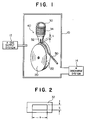
- FIG. 1 is a diagram illustrating the construction of an apparatus for the production of a thin soft magnetic alloy strip embodying the method of this invention for the production of a thin soft magnetic alloy strip.
- a vacuum chamber 10 is provided with a supply system 12 and a discharge system 14. Inside this vacuum chamber 10, a single-roll mechanism 40 consisting mainly of a cooling roll 20 capable of being cooled to a prescribed temperature and controlled to a prescribed peripheral speed and a raw material melting container 30.
- a nozzle 32 which opens in the direction of a peripheral surface 32 of the cooling roll 20.
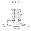
- the shape of the orifice of this nozzle 32 is rectangular as illustrated in Fig. 2.
- the short side of the rectangular cross section of the orifice falls parallelly to the circumferential direction of the cooling roll 20.
- the long side a and the short side b of the orifice of the nozzle 32 are to be set in accordance with the particular raw material to be used.
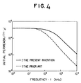
- the nozzle 32 are set so the appropriate distance c between the nozzle 32 and the peripheral surface 22 of the working roll 20 can be formed. This distance c can be varied depending on the particular raw material to be used.
- the angle of ejection onto the cooling roll 20 is not limited to 90°.
- An induction heating coil 34 is disposed on the outer periphery of the raw material melting container 30 and is used for melting the raw material to be introduced.
- the molten raw material is ejected through the nozzle 32 onto the peripheral surface 22 of the cooling roll 20.
- E (Cu or Au) in the aforementioned formula (II) represents an element effective in heightening the corrosion-resistance, preventing crystalline grains from being coarsened, and improving the soft magnetic properties such as core loss and permeability. It is particularly effective in the precipitation of the bcc phase at low temperatures. If the amount of this element is unduly small, the effects mentioned above are not obtained. Conversely, if this amount is unduly large, the magnetic properties are degraded.
- the content of E is in the range of 0.1 to 8 atomic %. Preferably, this range is from 0.1 to 5 atomic %.
- G (at least one element selected from the class consisting of the elements of Group IVa, the elements of Group Va, the elements of Group VIa, and the rare-earth elements) is an element for effectively uniformizing the diameter of crystalline grains, diminishing magnetostriction and magnetic anisotropy, improving the soft magnetic properties, and also improving the magnetic properties against temperature changes.
- the combined addition of G and E (Cu, for example) allows the stabilization of the bcc phase to be attained over a wide range of temperature. If the amount of this element, G, is unduly small, the aforementioned effects are not attained. Conversely, if this amount is unduly large, amorphous phase can not be obtained during the course of manufacture and, what is more, the saturated magnetic flux density is unduly low.
- the content of G therefore, is suitably in the range of 0.1 to 10 atomic %. Preferably, this range is from 1 to 8 atomic %.
- the elements of Group IVa are effective in widening the ranges of conditions of the heat treatment for the attainment of the optimum magnetic properties
- the elements of Group Va are effective in improving the resistance to embrittlement and improving the workability as for cutting
- the elements of Group VIa are effective in improving the corrosionresistance and improving the surface quality.
- Ta, Nb, W, and Mo are particularly effective in improving the soft magnetic properties and V is conspicuously effective in improving the resistance to embrittlement and the surface quality. These elements are, therefore, constitute themselves preferred choices.
- J (at least one element selected from the class consisting of Mn, Al, Ga, Ge, In, Sn, and the platinum-group elements) is an element effective in improving the soft magnetic properties or the corrosion resistant properties. If the amount of this element is unduly large, the saturated magnetic flux density is not sufficient. Thus, the upper limit of this amount is fixed at 10 atomic %.
- Al is particularly effective in promoting fine division of crystalline grains, improving the magnetic properties, and stabilizing the bcc phase
- Ge is effective in assisting the bcc phase
- the platinum-group elements is effective in improving the corrosion resistant properties.
- Si and B are elements effective in obtaining amorphous phase during the course of manufacture, improving the crystallizing temperature, and promoting the heat treatment for the improvement of the magnetic properties.
- Si forms a solid solution with Fe as the main component of microcrystalline grains and contributes to diminishing magnetostriction and magnetic anisotropy. If the amount of Si is less than 12 atomic %, the improvement of the soft magnetic properties is not conspicuous. If this amount exceeds 25 atomic %, the rapidly quenching effect is not sufficient, the educed crystalline grains are relatively coarse on the order of ⁇ m, and the soft magnetic properties are not satisfactory. Further, Si is an essential element for the construction of a order phase.
- the content of Si is preferably in the range of 12 to 22 atomic %. If the content of B is less than 3 atomic %, the educed crystalline grains are relatively coarse and do not exhibit satisfactory properties. If this content exceeds 12 atomic %, B is liable to form a compound of B in consequence of the heat treatment and the soft magnetic properties are not satisfactory.
- Z (C, N, or P) may be contained in the alloy composition in an amount of not more than 10 atomic %.
- the total amount of Si, B, and the element contributing to the conversion into the amorphous texture is desired to be in the range of 15 to 30 atomic %.
- Si and B are desired to be sued in such amounts as to satisfy the relation, Si/B ⁇ 1.
- the content of Si is in the range of 13 to 21 atomic %, the diminution of magnetostriction, ⁇ s, close to 0 is attained, the deterioration of the magnetic properties by resin mold is eliminated, and the outstanding soft magnetic properties aimed at are effectively manifested.
- the effect of this invention is not impaired when the Fe-based soft magnetic alloy mentioned above contains in a very small amount such unavoidable impurities as O and S which are contained in ordinary Fe-based alloys.
- the molten alloy composition is ejected under a pressure of 0.03 kg/cm 2 through the nozzle 32 onto the peripheral surface of the cooling roll 20 operated at a controlled peripheral speed of not less than 20 m/sec, to quench the molted metal and produce a thin amorphous strip 40.
- the reason for setting the upper limit of the reduced pressure or the pressure of the atmosphere of inert gas at 10 -2 Torr or 60 Torrs is that particularly in the production of a thin strip of a large width exceeding 1.5 mm, the thin strip having a sufficient small thickness, excelling in surface quality, and containing no pinhole is obtained when the upper limit is not surpassed. If this upper limit is surpassed, the produced thin strip acquires a laterally undulating surface, abounds with pinholes, and fails to acquire a thickness of not more than 10 ⁇ m.
- the peripheral speed is required only to exceed 20 m/sec. In view of the facility of manufacture of the thin strip, however, this peripheral speed is desired to be not more than 50 m/sec.
- the pressure for the ejection of the molten alloy is required only not to exceed 0.03 kg/cm 2 , desirably not more than 0.025 kg/cm 2 , and more desirably not more than 0.02 kg/cm 2 . If this pressure is less than 0.001 kg/cm 2 , the ejection of the molten metal is not easily attained.
- the cooling roll 20 is desired to be made of a Cu-based alloy (such as, for example, brass). Where the plate thickness of the thin strip to be produced is not more than 8 ⁇ m, the cooling roll 20 may be made of a Fe-based alloy. The cooling roll made of this material allows the produced thin strip to acquire improved surface quality and fine quality.
- the long side a of the rectangular cross section of the orifice of the nozzle 32 determines the width of the produced thin strip. It is required only to exceed 2 mm.
- the short side b constitutes itself an important value for determining the plate thickness of the thin strip.
- the value of b is desired to be not more than 0.2 mm, preferably not more than 0.15 mm. In due consideration of the ejectability of the molten metal, however, the value of b is desired to be not less than 0.07 mm.
- the distance c between the leading end of the nozzle 32 and the cooling roll 20 is not more than 0.2 mm.
- the reason for this upper limit is that the strip is not easily obtained in an extremely small thickness if this distance exceeds 0.20 mm. If this distance c is unduly small, the produced thin strip suffers from inferior surface quality. Thus, the distance is desired to be not less than 0.05 mm.
- the thin strip 40 of an amorphous state is obtained in a thickness of not more than 10 ⁇ m.
- the thin amorphous layer obtained as described above is subjected to a heat treatment at a suitable temperature exceeding the crystallizing temperature of the amorphous alloy for a period in the range of 10 minutes to 15 hours.
- This heat treatment allows the thin amorphous strip to effect precipitation of not more than 1000 ⁇ microcrystalline grains and acquire improved magnetic properties.
- the thin Fe-based microcrystalline alloy strip may be given an additional heat treatment in the presence of a magnetic field (in the direction of the axis of the thin strip, the direction of the width, the direction of the thickness, or in the rotary magnetic field).
- the kind of the atmosphere in which this heat treatment is carried out is not critical.
- the heat treatment effectively proceeds in the insert gas such as N 2 or Ar, in the vacuum, in the reducing atmosphere such as of H 2 , or in the ambient air, for example.
- the microcrystalline grains not more than 1,000 ⁇ in diameter present in the thin Fe-based microcrystalline alloy strip obtained as described above are desired to be such that they exist therein in an area ratio in the range of 25 to 95%. If the area ratio of the microcrystalline grains is unduly small, namely if the area ratio of the amorphous is unduly large, the core loss is large, the permeability low, and the magnetostriction large. Conversely, if the area ratio of the microcrystalline grains is unduly large, the magnetic properties are unsatisfactory.
- the preferable ratio of presence of the microcrystalline grains in the alloy is in the range of 40 to 90% as area ratio. Within this range, the soft magnetic properties are obtained particularly stably.
- the reason for setting the upper limit of the thickness of the thin Fe-based microcrystalline alloy strip at 10 ⁇ m is that the magnetic properties in the high frequency range such as of MHz are highly satisfactory and the resistance to embrittlement is improved when this upper limit is observed.
- the improvement of the resistance to embrittlement is prominent when the thickness is restricted below 8 ⁇ m.
- An alloy composition represented by the formula, Fe 72 Cu 1 V 6 Si 13 B 8 was prepared, placed in the raw material melting container, and melted therein.
- the nozzle used herein had a rectangular orifice measuring 5.2 mm x 0.15 mm (a x b). The distance c between the nozzle and the cooling roll was 0.15 mm.
- the cooling roll was made of a Cu alloy.
- the molten alloy composition was ejected under a pressure of 0.025 kg/cm 2 through the nozzle onto the peripheral surface of the cooling roll operated under a controlled peripheral speed of 42 m/sec, to quench the molten metal and obtain a thin strip.
- the thin strip thus obtained measured 5 mm in width and 7.8 ⁇ m in thickness and possessed an amorphous state.
- the thin strip was wound in a toroidal core with 12 mm outermost diameter and 8mm inner diameter).
- This core was subjected to a heat treatment in an atmosphere of N 2 at 570°C for two hours.
- the core after the heat treatment was tested for core loss, and frequency characteristic of initial permeability by the use of a U function meter and a LCR meter.
- Fig. 4 shows the frequency characteristic of the initial permeability in an excited magnetic field of 2mOe.
- the results similarly obtained of a thin Fe-based microcrystalline alloy strip using the same alloy composition and possessing a thickness of 18 ⁇ m are shown in the diagram.
- the thin Fe-based microcrystalline alloy strips of Example 4 and Comparative Experiment 4 were subjected to a bending test. This test was carried out by disposing a given thin heat-treated Fe-based microcrystalline alloy strip in a bent state between two plates, narrowing the distance between the two plates until the bent sample broke, measuring the distance, l, between the two plates at the time of breakage of the sample, and calculating the following formula using the found distance .
- ⁇ t l - t (wherein t stands for the average thickness of the sample thin strip by gravimetric method based on weight / density x length x width ).
- ⁇ is not less than 1 x 10 -3 , preferably not less than 3 x 10 -3 .
- Thin amorphous strips were produced by following the procedure of Example 4, excepting varying alloy compositions indicated in Table 2 were used instead and the conditions of production were varied as indicated in Table 2. Then, the thin strips were wound to produce cores and the cores were heat-treated similarly.
Landscapes
- Engineering & Computer Science (AREA)
- Power Engineering (AREA)
- Physics & Mathematics (AREA)
- Electromagnetism (AREA)
- Chemical & Material Sciences (AREA)
- Dispersion Chemistry (AREA)
- Mechanical Engineering (AREA)
- Manufacturing & Machinery (AREA)
- Soft Magnetic Materials (AREA)
- Continuous Casting (AREA)
Claims (4)
- Procédé de production d'un mince ruban d'alliage magnétique doux à base de Fe ayant une épaisseur non supérieure à 10 µm, caractérisé par le fait qu'un alliage fondu est éjecté à travers une buse sur la surface d'un élément de refroidissement rotatif en présence d'une pression d'éjection non supérieure à 0,03 kg/cm2 dans une atmosphère de pression réduite non supérieure à 1,33 Nm-2 (1 x 10⁻² Torr), ou dans une atmosphère He de pression réduite, non supérieure à 8000 Nm-2 (60 Torr), entraínant ainsi une trempe rapide dudit alliage fondu éjecté pour produire ledit ruban, ladite buse comportant un orifice à section transversale rectangulaire, dont le côté court, incliné parallèlement à la direction périphérique dudit élément de refroidissement rotatif, est réglé à 0,2 mm ou à une valeur inférieure, la distance entre ladite buse et ledit élément de refroidissement rotatif étant réglé à 0,2 mm ou à une valeur inférieure, et ledit élément de refroidissement rotatif étant tourné à une vitesse périphérique non inférieure à 20 m/seconde, ledit mince ruban étant ensuite soumis à un traitement thermique à une température dépassant la température de cristallisation de l'alliage utilisé, ledit ruban contenant des grains microcristallins ayant un diamètre non supérieur à 100 nm (1.000 Å).
- Procédé selon la revendication 1, dans lequel ledit élément de refroidissement rotatif est composé d'un alliage à base de Cu.
- Procédé selon la revendication 1, dans lequel l'épaisseur dudit mince ruban d'alliage à base de Fe n'est pas supérieure à 8 µm.
- Procédé selon l'une quelconque des revendications 1 à 3, dans lequel ledit mince ruban d'alliage magnétique doux à base de Fe devant être produit a une composition d'alliage représentée en substance par la formule générale Fe100-e-f-g-h-i-jEeGfJgSihBiZj, E représentant au moins un élément choisi dans le groupe le groupe constitué de Cu et de Au, G représentant au moins un élément choisi dans le groupe constitué des éléments du groupe IVa, des éléments du groupe Va, des éléments du groupe VIa, et des éléments de terre rare, J représentant au moins un élément choisi dans le groupe constitué de Mn, Al, Ga, Ge, In, Sn et des éléments du groupe de platine, Z représentant au moins un élément choisi dans le groupe constitué de C, N et P et e, f, g, h, i et j représentant un % atomique satisfaisant à la relation 0,1 < e < 8, 0,1 < f < 10, 0 < g < 10, 12 < h < 25, 3 < i < 12, 0 < j < 10, et 15 < h + i + j < 30.
Priority Applications (2)
| Application Number | Priority Date | Filing Date | Title |
|---|---|---|---|
| EP97108840A EP0800182B1 (fr) | 1989-09-01 | 1989-09-01 | Bande mince en alliage, magnétiquement douce |
| DE1989628741 DE68928741T2 (de) | 1989-09-01 | 1989-09-01 | Verfahren zur Herstellung eines Legierungsbandes auf Eisenbasis nicht dicker als 10 mikrometer |
Applications Claiming Priority (1)
| Application Number | Priority Date | Filing Date | Title |
|---|---|---|---|
| EP89308903A EP0414974B1 (fr) | 1989-09-01 | 1989-09-01 | Bande mince en alliage, magnétiquement douce |
Related Parent Applications (2)
| Application Number | Title | Priority Date | Filing Date |
|---|---|---|---|
| EP89308903A Division EP0414974B1 (fr) | 1989-09-01 | 1989-09-01 | Bande mince en alliage, magnétiquement douce |
| EP89308903.7 Division | 1989-09-01 |
Related Child Applications (1)
| Application Number | Title | Priority Date | Filing Date |
|---|---|---|---|
| EP97108840A Division EP0800182B1 (fr) | 1989-09-01 | 1989-09-01 | Bande mince en alliage, magnétiquement douce |
Publications (2)
| Publication Number | Publication Date |
|---|---|
| EP0612082A1 EP0612082A1 (fr) | 1994-08-24 |
| EP0612082B1 true EP0612082B1 (fr) | 1998-07-15 |
Family
ID=8202777
Family Applications (3)
| Application Number | Title | Priority Date | Filing Date |
|---|---|---|---|
| EP94106741A Expired - Lifetime EP0612082B1 (fr) | 1989-09-01 | 1989-09-01 | Procédé de fabrication d'un ruban en alliage à basé de fer de 10 micromètres ou moins |
| EP89308903A Expired - Lifetime EP0414974B1 (fr) | 1989-09-01 | 1989-09-01 | Bande mince en alliage, magnétiquement douce |
| EP97108840A Expired - Lifetime EP0800182B1 (fr) | 1989-09-01 | 1989-09-01 | Bande mince en alliage, magnétiquement douce |
Family Applications After (2)
| Application Number | Title | Priority Date | Filing Date |
|---|---|---|---|
| EP89308903A Expired - Lifetime EP0414974B1 (fr) | 1989-09-01 | 1989-09-01 | Bande mince en alliage, magnétiquement douce |
| EP97108840A Expired - Lifetime EP0800182B1 (fr) | 1989-09-01 | 1989-09-01 | Bande mince en alliage, magnétiquement douce |
Country Status (3)
| Country | Link |
|---|---|
| US (2) | US5096513A (fr) |
| EP (3) | EP0612082B1 (fr) |
| DE (1) | DE68920324T2 (fr) |
Families Citing this family (54)
| Publication number | Priority date | Publication date | Assignee | Title |
|---|---|---|---|---|
| EP0422760A1 (fr) * | 1989-10-12 | 1991-04-17 | Mitsubishi Rayon Co., Ltd | Alliage amorphe et procédé pour sa fabrication |
| WO1993023583A1 (fr) * | 1992-05-14 | 1993-11-25 | Mitsubishi Rayon Co., Ltd. | Alliage amorphe et production |
| KR0149065B1 (ko) * | 1993-08-23 | 1998-11-16 | 도끼와 히꼬끼찌 | 무정형 합금리본 제조방법 |
| JP3891448B2 (ja) * | 1994-04-11 | 2007-03-14 | 日立金属株式会社 | 薄型アンテナおよびそれを用いたカード |
| DE19615921A1 (de) * | 1996-04-22 | 1997-10-23 | Vacuumschmelze Gmbh | Induktives Bauelement in flacher Bauform |
| FR2755292B1 (fr) * | 1996-10-25 | 1998-11-20 | Mecagis | Procede de fabrication d'un noyau magnetique en materiau magnetique doux nanocristallin |
| EP0959478B1 (fr) * | 1997-02-06 | 2004-03-31 | Sumitomo Special Metals Company Limited | Procede de fabrication d'un aimant a plaque mince possedant une structure microcristalline |
| WO1998038348A1 (fr) * | 1997-02-27 | 1998-09-03 | Fmc Corporation | Alliages metalliques amorphes et amorphes/microcristallins et procedes de production |
| US6603236B2 (en) | 1998-01-22 | 2003-08-05 | Seiko Epson Corporation | Electronic timepiece |
| DE19851871C2 (de) * | 1998-11-10 | 2001-06-07 | Vacuumschmelze Gmbh | Verfahren zur Herstellung eines in sich geschlossenen Magnetkerns |
| JP4128721B2 (ja) * | 2000-03-17 | 2008-07-30 | 株式会社東芝 | 情報記録物品 |
| JP2002280224A (ja) * | 2001-01-05 | 2002-09-27 | Humanelecs Co Ltd | アモルファス合金粉末コア及びナノクリスタル合金粉末コア並びにそれらの製造方法 |
| US6906495B2 (en) | 2002-05-13 | 2005-06-14 | Splashpower Limited | Contact-less power transfer |
| GB2388716B (en) | 2002-05-13 | 2004-10-20 | Splashpower Ltd | Improvements relating to contact-less power transfer |
| US7426780B2 (en) * | 2004-11-10 | 2008-09-23 | Enpirion, Inc. | Method of manufacturing a power module |
| US7462317B2 (en) * | 2004-11-10 | 2008-12-09 | Enpirion, Inc. | Method of manufacturing an encapsulated package for a magnetic device |
| AU2005335007B2 (en) * | 2005-07-25 | 2011-11-03 | Zhuwen Ming | L, R, C method and equipment for continuous casting amorphous, ultracrystallite and crystallite metallic slab or strip |
| US8139362B2 (en) | 2005-10-05 | 2012-03-20 | Enpirion, Inc. | Power module with a magnetic device having a conductive clip |
| US8701272B2 (en) | 2005-10-05 | 2014-04-22 | Enpirion, Inc. | Method of forming a power module with a magnetic device having a conductive clip |
| US7688172B2 (en) * | 2005-10-05 | 2010-03-30 | Enpirion, Inc. | Magnetic device having a conductive clip |
| US8631560B2 (en) * | 2005-10-05 | 2014-01-21 | Enpirion, Inc. | Method of forming a magnetic device having a conductive clip |
| US8133529B2 (en) * | 2007-09-10 | 2012-03-13 | Enpirion, Inc. | Method of forming a micromagnetic device |
| US8018315B2 (en) * | 2007-09-10 | 2011-09-13 | Enpirion, Inc. | Power converter employing a micromagnetic device |
| US7920042B2 (en) | 2007-09-10 | 2011-04-05 | Enpirion, Inc. | Micromagnetic device and method of forming the same |
| US8692532B2 (en) | 2008-04-16 | 2014-04-08 | Enpirion, Inc. | Power converter with controller operable in selected modes of operation |
| US9246390B2 (en) * | 2008-04-16 | 2016-01-26 | Enpirion, Inc. | Power converter with controller operable in selected modes of operation |
| US8686698B2 (en) * | 2008-04-16 | 2014-04-01 | Enpirion, Inc. | Power converter with controller operable in selected modes of operation |
| US8541991B2 (en) | 2008-04-16 | 2013-09-24 | Enpirion, Inc. | Power converter with controller operable in selected modes of operation |
| US8339802B2 (en) * | 2008-10-02 | 2012-12-25 | Enpirion, Inc. | Module having a stacked magnetic device and semiconductor device and method of forming the same |
| US8153473B2 (en) * | 2008-10-02 | 2012-04-10 | Empirion, Inc. | Module having a stacked passive element and method of forming the same |
| US8266793B2 (en) * | 2008-10-02 | 2012-09-18 | Enpirion, Inc. | Module having a stacked magnetic device and semiconductor device and method of forming the same |
| US9054086B2 (en) * | 2008-10-02 | 2015-06-09 | Enpirion, Inc. | Module having a stacked passive element and method of forming the same |
| US8698463B2 (en) * | 2008-12-29 | 2014-04-15 | Enpirion, Inc. | Power converter with a dynamically configurable controller based on a power conversion mode |
| US9548714B2 (en) * | 2008-12-29 | 2017-01-17 | Altera Corporation | Power converter with a dynamically configurable controller and output filter |
| US8867295B2 (en) | 2010-12-17 | 2014-10-21 | Enpirion, Inc. | Power converter for a memory module |
| CN102529227A (zh) * | 2011-11-25 | 2012-07-04 | 南昌大学 | 一种以铁基非晶/纳米晶带材做贴片层的电磁屏蔽复合材料制备方法 |
| IN2014DN08436A (fr) * | 2012-03-15 | 2015-05-08 | Hitachi Metalsltd | |
| US8485245B1 (en) * | 2012-05-16 | 2013-07-16 | Crucible Intellectual Property, Llc | Bulk amorphous alloy sheet forming processes |
| CN103611896B (zh) * | 2013-12-04 | 2016-03-30 | 南昌航空大学 | 一种通过电弧熔炼和熔体快淬制备MnCoGe基和MnNiGe基合金薄带的方法 |
| EP2982460A1 (fr) * | 2014-08-07 | 2016-02-10 | Max-Planck-Gesellschaft zur Förderung der Wissenschaften e.V. | Appareil et procédé de fabrication de torons métalliques ou inorganiques ayant une épaisseur dans la gamme micrométrique par filage par fusion |
| US9509217B2 (en) | 2015-04-20 | 2016-11-29 | Altera Corporation | Asymmetric power flow controller for a power converter and method of operating the same |
| CN104802042B (zh) * | 2015-04-24 | 2018-07-24 | 天津理工大学 | 一种提高非晶软磁合金初始磁导率及其交流磁性的方法 |
| EP3141320A1 (fr) * | 2015-09-11 | 2017-03-15 | Max-Planck-Gesellschaft zur Förderung der Wissenschaften e.V. | Appareil et procédé de fabrication de fibres métalliques ou inorganiques ayant une épaisseur dans la gamme micrométrique par filage par fusion |
| US10017851B2 (en) * | 2015-12-22 | 2018-07-10 | Texas Instruments Incorporated | Magnetic field annealing for integrated fluxgate sensors |
| JP6237853B1 (ja) * | 2016-09-30 | 2017-11-29 | Tdk株式会社 | 軟磁性合金 |
| CN106424618B (zh) * | 2016-11-09 | 2019-04-19 | 浙江师范大学 | 一种无缠绕高效率的非晶细带制备方法 |
| CN106799479A (zh) * | 2017-03-17 | 2017-06-06 | 山东三尺企业管理咨询有限公司 | 直流磁场改变非晶喷带磁畴取向的方法及装置 |
| CN107414040A (zh) * | 2017-07-31 | 2017-12-01 | 芜湖君华材料有限公司 | 一种铁基非晶带材防氧化气密性制备装置 |
| CN107829047A (zh) * | 2017-11-02 | 2018-03-23 | 东南大学 | 高非晶形成能力大塑性钴基块体非晶合金及其制备方法 |
| CN108031807B (zh) * | 2017-12-25 | 2020-01-07 | 洛阳中赫非晶科技有限公司 | 带材的制造装置和方法 |
| CN115574481A (zh) | 2018-09-28 | 2023-01-06 | 株式会社东芝 | 蓄冷材料、冷冻机、超导线圈内置装置以及蓄冷材料的制造方法 |
| CN110153384B (zh) * | 2019-06-21 | 2020-12-15 | 中国矿业大学 | 一种全金属铁基非晶条带的制备方法 |
| CN111001767B (zh) * | 2019-12-31 | 2021-10-22 | 武汉科技大学 | 一种高饱和磁感应强度铁基非晶软磁合金及其制备方法 |
| CN119650237B (zh) * | 2024-12-10 | 2025-11-14 | 中国科学院宁波材料技术与工程研究所 | 一种钴基非晶软磁合金材料及其制备和基于软磁合金的复合吸波结构 |
Family Cites Families (23)
| Publication number | Priority date | Publication date | Assignee | Title |
|---|---|---|---|---|
| CA1068470A (fr) * | 1975-02-24 | 1979-12-25 | Allied Chemical Corporation | Production de filaments ameliores faits d'alliage metallique |
| US4225339A (en) * | 1977-12-28 | 1980-09-30 | Tokyo Shibaura Denki Kabushiki Kaisha | Amorphous alloy of high magnetic permeability |
| SE448381B (sv) * | 1978-09-19 | 1987-02-16 | Tsuya Noboru | Sett att framstella ett tunt band av kiselstal, tunt kiselstalband och anvendning av dylikt |
| JPS55161057A (en) * | 1979-06-04 | 1980-12-15 | Sony Corp | Manufacture of high permeability amorphous alloy |
| US4249969A (en) * | 1979-12-10 | 1981-02-10 | Allied Chemical Corporation | Method of enhancing the magnetic properties of an Fea Bb Sic d amorphous alloy |
| JPS57185947A (en) * | 1981-05-06 | 1982-11-16 | Hitachi Metals Ltd | Amorphous alloy |
| JPS5831053A (ja) * | 1981-08-18 | 1983-02-23 | Toshiba Corp | 非晶質合金 |
| JPS5844702A (ja) * | 1981-09-11 | 1983-03-15 | Toshiba Corp | 高周波用非晶質磁性合金の磁心 |
| JPS58139408A (ja) * | 1982-02-15 | 1983-08-18 | Hitachi Metals Ltd | 巻鉄心の製造方法 |
| JPS619947A (ja) * | 1984-06-25 | 1986-01-17 | Kawasaki Steel Corp | 非晶質合金薄帯の製造方法 |
| JPS61123119A (ja) * | 1984-11-20 | 1986-06-11 | Hitachi Metals Ltd | C0基磁心およびその熱処理方法 |
| JPS61136629A (ja) * | 1984-12-04 | 1986-06-24 | Mitsubishi Electric Corp | 鉄系アモルフアス磁性材料の焼鈍方法 |
| US4938267A (en) * | 1986-01-08 | 1990-07-03 | Allied-Signal Inc. | Glassy metal alloys with perminvar characteristics |
| US4859256A (en) * | 1986-02-24 | 1989-08-22 | Kabushiki Kaisha Toshiba | High permeability amorphous magnetic material |
| JPS6246900A (ja) * | 1986-08-20 | 1987-02-28 | 日本石油化学株式会社 | スリツプシ−トを用いる荷役方法 |
| JP2513645B2 (ja) * | 1986-10-14 | 1996-07-03 | 日立金属株式会社 | 実効パルス透磁率に優れたアモルファス磁心およびその製造方法 |
| JP2618232B2 (ja) * | 1986-11-18 | 1997-06-11 | 株式会社日本紙パルプ研究所 | 製紙用填料及びその製造法 |
| JPS63135592A (ja) * | 1986-11-25 | 1988-06-07 | 日本フエルト株式会社 | 走行紙の水分率測定装置 |
| US4881989A (en) * | 1986-12-15 | 1989-11-21 | Hitachi Metals, Ltd. | Fe-base soft magnetic alloy and method of producing same |
| EP0284832A1 (fr) * | 1987-03-20 | 1988-10-05 | Siemens Aktiengesellschaft | Procédé de production d'un matériau magnétique anisotrope à base de Fe, B, et un métal de terre rare |
| JP2573606B2 (ja) * | 1987-06-02 | 1997-01-22 | 日立金属 株式会社 | 磁心およびその製造方法 |
| JPH0680611B2 (ja) * | 1987-10-23 | 1994-10-12 | 日立金属株式会社 | 磁 心 |
| JP2823203B2 (ja) * | 1988-05-17 | 1998-11-11 | 株式会社東芝 | Fe基軟磁性合金 |
-
1989
- 1989-09-01 EP EP94106741A patent/EP0612082B1/fr not_active Expired - Lifetime
- 1989-09-01 EP EP89308903A patent/EP0414974B1/fr not_active Expired - Lifetime
- 1989-09-01 EP EP97108840A patent/EP0800182B1/fr not_active Expired - Lifetime
- 1989-09-01 DE DE68920324T patent/DE68920324T2/de not_active Expired - Fee Related
- 1989-09-01 US US07/401,418 patent/US5096513A/en not_active Expired - Lifetime
-
1992
- 1992-12-10 US US07/988,702 patent/US5334262A/en not_active Expired - Fee Related
Also Published As
| Publication number | Publication date |
|---|---|
| EP0612082A1 (fr) | 1994-08-24 |
| US5096513A (en) | 1992-03-17 |
| DE68920324D1 (de) | 1995-02-09 |
| EP0414974A1 (fr) | 1991-03-06 |
| EP0800182B1 (fr) | 2002-11-13 |
| EP0800182A1 (fr) | 1997-10-08 |
| US5334262A (en) | 1994-08-02 |
| EP0414974B1 (fr) | 1994-12-28 |
| DE68920324T2 (de) | 1995-06-29 |
Similar Documents
| Publication | Publication Date | Title |
|---|---|---|
| EP0800182B1 (fr) | Bande mince en alliage, magnétiquement douce | |
| JP5720674B2 (ja) | 初期超微結晶合金、ナノ結晶軟磁性合金及びその製造方法、並びにナノ結晶軟磁性合金からなる磁性部品 | |
| JP4310480B2 (ja) | アモルファス合金組成物 | |
| JP6191908B2 (ja) | ナノ結晶軟磁性合金及びこれを用いた磁性部品 | |
| EP1045402A2 (fr) | Bande mince en alliage, magnétiquement douce, procédé de fabrication et utilisation | |
| JP3594123B2 (ja) | 合金薄帯並びにそれを用いた部材、及びその製造方法 | |
| EP2757172A1 (fr) | Caoutchouc d'alliage de cristaux ultra fins initiaux à base de fer (fe) et composant magnétique | |
| EP1001437A1 (fr) | Alliage magnétique à base de fer magnétiquement doux, noyau magnétique de cela et procédé de fabrication | |
| CA2210017C (fr) | Methode pour fabriquer un alliage magnetique mou a base de fer | |
| JP4623400B2 (ja) | 軟磁性合金薄帯ならびにそれを用いた磁心及び装置 | |
| JP2006040906A (ja) | 高透磁率かつ高飽和磁束密度の軟磁性成形体の製造方法 | |
| JP2004353090A (ja) | 合金薄帯並びにそれを用いた部材 | |
| JP4257629B2 (ja) | ナノ結晶軟磁性合金用Fe基アモルファス合金薄帯及び磁性部品 | |
| JP2848667B2 (ja) | 極薄軟磁性合金薄帯の製造方法 | |
| US5198040A (en) | Very thin soft magnetic Fe-based alloy strip and magnetic core and electromagnetic apparatus made therefrom | |
| JPH05255820A (ja) | 恒透磁率性を有するFe基合金とその製造方法、およびそれを用いたFe基磁心 | |
| KR920007580B1 (ko) | Fe기 연자성 합금 | |
| JP2000119825A (ja) | Fe基アモルファス合金薄帯およびそれを用いたFe基ナノ結晶軟磁性合金薄帯ならびに磁心 | |
| JP4798642B2 (ja) | 高靱性Fe基アモルファス合金および高靱性Fe基アモルファス合金から製造されたFe基ナノ結晶合金を用いた部品 | |
| JPH1046301A (ja) | Fe基磁性合金薄帯ならびに磁心 | |
| JPH0867911A (ja) | ナノ結晶磁性合金の熱処理方法 | |
| KR100220874B1 (ko) | 극박형 Fe-Al계 연자성 합금 및 그의 제조 방법 | |
| EP0473782B1 (fr) | Noyau magnetique | |
| JP2815926B2 (ja) | 磁性コア | |
| JP7610097B2 (ja) | Fe系合金薄帯及びFe系非晶質合金薄帯 |
Legal Events
| Date | Code | Title | Description |
|---|---|---|---|
| PUAI | Public reference made under article 153(3) epc to a published international application that has entered the european phase |
Free format text: ORIGINAL CODE: 0009012 |
|
| 17P | Request for examination filed |
Effective date: 19940523 |
|
| AC | Divisional application: reference to earlier application |
Ref document number: 414974 Country of ref document: EP |
|
| AK | Designated contracting states |
Kind code of ref document: A1 Designated state(s): DE FR GB |
|
| RIN1 | Information on inventor provided before grant (corrected) |
Inventor name: YAGI, MASAAKI Inventor name: SAWA, TAKAO, C/O PATENT DIVISION |
|
| 17Q | First examination report despatched |
Effective date: 19950817 |
|
| GRAG | Despatch of communication of intention to grant |
Free format text: ORIGINAL CODE: EPIDOS AGRA |
|
| GRAG | Despatch of communication of intention to grant |
Free format text: ORIGINAL CODE: EPIDOS AGRA |
|
| GRAH | Despatch of communication of intention to grant a patent |
Free format text: ORIGINAL CODE: EPIDOS IGRA |
|
| GRAH | Despatch of communication of intention to grant a patent |
Free format text: ORIGINAL CODE: EPIDOS IGRA |
|
| GRAA | (expected) grant |
Free format text: ORIGINAL CODE: 0009210 |
|
| AC | Divisional application: reference to earlier application |
Ref document number: 414974 Country of ref document: EP |
|
| AK | Designated contracting states |
Kind code of ref document: B1 Designated state(s): DE FR GB |
|
| XX | Miscellaneous (additional remarks) |
Free format text: TEILANMELDUNG 97108840.6 EINGEREICHT AM 03/06/97. |
|
| REF | Corresponds to: |
Ref document number: 68928741 Country of ref document: DE Date of ref document: 19980820 |
|
| ET | Fr: translation filed | ||
| PLBE | No opposition filed within time limit |
Free format text: ORIGINAL CODE: 0009261 |
|
| STAA | Information on the status of an ep patent application or granted ep patent |
Free format text: STATUS: NO OPPOSITION FILED WITHIN TIME LIMIT |
|
| 26N | No opposition filed | ||
| REG | Reference to a national code |
Ref country code: GB Ref legal event code: IF02 |
|
| PGFP | Annual fee paid to national office [announced via postgrant information from national office to epo] |
Ref country code: GB Payment date: 20030827 Year of fee payment: 15 |
|
| PGFP | Annual fee paid to national office [announced via postgrant information from national office to epo] |
Ref country code: FR Payment date: 20030909 Year of fee payment: 15 |
|
| PGFP | Annual fee paid to national office [announced via postgrant information from national office to epo] |
Ref country code: DE Payment date: 20030911 Year of fee payment: 15 |
|
| PG25 | Lapsed in a contracting state [announced via postgrant information from national office to epo] |
Ref country code: GB Free format text: LAPSE BECAUSE OF NON-PAYMENT OF DUE FEES Effective date: 20040901 |
|
| REG | Reference to a national code |
Ref country code: FR Ref legal event code: CA |
|
| PG25 | Lapsed in a contracting state [announced via postgrant information from national office to epo] |
Ref country code: DE Free format text: LAPSE BECAUSE OF NON-PAYMENT OF DUE FEES Effective date: 20050401 |
|
| GBPC | Gb: european patent ceased through non-payment of renewal fee |
Effective date: 20040901 |
|
| PG25 | Lapsed in a contracting state [announced via postgrant information from national office to epo] |
Ref country code: FR Free format text: LAPSE BECAUSE OF NON-PAYMENT OF DUE FEES Effective date: 20050531 |
|
| REG | Reference to a national code |
Ref country code: FR Ref legal event code: ST |