EP0612092A1 - Schutzschalter mit anpassbarer Fernbetätigungseinheit - Google Patents
Schutzschalter mit anpassbarer Fernbetätigungseinheit Download PDFInfo
- Publication number
- EP0612092A1 EP0612092A1 EP94420034A EP94420034A EP0612092A1 EP 0612092 A1 EP0612092 A1 EP 0612092A1 EP 94420034 A EP94420034 A EP 94420034A EP 94420034 A EP94420034 A EP 94420034A EP 0612092 A1 EP0612092 A1 EP 0612092A1
- Authority
- EP
- European Patent Office
- Prior art keywords
- circuit breaker
- control unit
- remote control
- remote
- handle
- Prior art date
- Legal status (The legal status is an assumption and is not a legal conclusion. Google has not performed a legal analysis and makes no representation as to the accuracy of the status listed.)
- Granted
Links
- 230000007246 mechanism Effects 0.000 claims abstract description 62
- 238000004873 anchoring Methods 0.000 claims abstract description 19
- 230000006978 adaptation Effects 0.000 claims description 8
- 238000004146 energy storage Methods 0.000 claims description 8
- 230000010287 polarization Effects 0.000 claims description 5
- 230000000903 blocking effect Effects 0.000 claims description 4
- 230000002452 interceptive effect Effects 0.000 claims description 3
- 230000011664 signaling Effects 0.000 claims description 3
- 230000008878 coupling Effects 0.000 claims description 2
- 238000010168 coupling process Methods 0.000 claims description 2
- 238000005859 coupling reaction Methods 0.000 claims description 2
- 239000003638 chemical reducing agent Substances 0.000 claims 1
- 238000009434 installation Methods 0.000 description 4
- 241001272720 Medialuna californiensis Species 0.000 description 2
- 230000009471 action Effects 0.000 description 2
- 230000006872 improvement Effects 0.000 description 2
- 238000009825 accumulation Methods 0.000 description 1
- 230000005540 biological transmission Effects 0.000 description 1
- 230000006835 compression Effects 0.000 description 1
- 238000007906 compression Methods 0.000 description 1
- 238000003780 insertion Methods 0.000 description 1
- 230000037431 insertion Effects 0.000 description 1
- 238000012423 maintenance Methods 0.000 description 1
- 238000004519 manufacturing process Methods 0.000 description 1
- 238000012986 modification Methods 0.000 description 1
- 230000004048 modification Effects 0.000 description 1
- 230000005405 multipole Effects 0.000 description 1
- 238000000926 separation method Methods 0.000 description 1
- 230000000087 stabilizing effect Effects 0.000 description 1
Images




Classifications
-
- H—ELECTRICITY
- H01—ELECTRIC ELEMENTS
- H01H—ELECTRIC SWITCHES; RELAYS; SELECTORS; EMERGENCY PROTECTIVE DEVICES
- H01H71/00—Details of the protective switches or relays covered by groups H01H73/00 - H01H83/00
- H01H71/10—Operating or release mechanisms
- H01H71/66—Power reset mechanisms
- H01H71/70—Power reset mechanisms actuated by electric motor
-
- H—ELECTRICITY
- H01—ELECTRIC ELEMENTS
- H01H—ELECTRIC SWITCHES; RELAYS; SELECTORS; EMERGENCY PROTECTIVE DEVICES
- H01H1/00—Contacts
- H01H1/12—Contacts characterised by the manner in which co-operating contacts engage
- H01H1/14—Contacts characterised by the manner in which co-operating contacts engage by abutting
- H01H1/20—Bridging contacts
- H01H1/2041—Rotating bridge
-
- H—ELECTRICITY
- H01—ELECTRIC ELEMENTS
- H01H—ELECTRIC SWITCHES; RELAYS; SELECTORS; EMERGENCY PROTECTIVE DEVICES
- H01H71/00—Details of the protective switches or relays covered by groups H01H73/00 - H01H83/00
- H01H71/10—Operating or release mechanisms
- H01H71/66—Power reset mechanisms
- H01H2071/665—Power reset mechanisms the reset mechanism operating directly on the normal manual operator, e.g. electromagnet pushes manual release lever back into "ON" position
Definitions
- a remote control unit is attached to the basic device to allow remote operation.
- the closing energy of the contacts and the operating system of the second mechanism is housed in a module which covers the lever to operate the device, and also take the information of the position of the poles to actuate the open display members / closed fixed on the remote control unit. It is therefore imperative to precisely position the remote control unit on the circuit breaker to correctly drive the handle, to transmit the local opening order to the first mechanism, and to pick up the position of the contacts.
- the object of the invention is to provide a circuit breaker with an adaptable remote control unit, guaranteeing both the positioning and the matching of states of the mechanical control members, and the ease of adaptation, interchangeability and connection of auxiliaries.
- the remote-controlled circuit breaker according to the invention is characterized in that the lower part of at least one plate of the second mechanism comprises a first anchoring element intended to cooperate with a second anchoring element provided on the upper part of the corresponding plate of the first mechanism, the coming into engagement of the first and second anchoring elements at the end of the tilting stroke of the remote control unit, causing automatic centering of the second mechanism on the first mechanism.
- the spacing between the two parallel plates of the second mechanism is identical to that of the plates of the first mechanism.
- the upper face of the adapter plate carries a connection terminal block, and is provided with at least one lateral opening for access to the compartments for housing the auxiliary blocks provided in the case of the circuit breaker.
- the presence of the anchoring elements on the plates makes it possible to obtain perfect positioning of the mechanical members of the two mechanisms, which generates an improvement in the chain of dimensions for mounting.
- the configuration of the adapter plate allows after switching the remote control unit, free access to the connection terminal block and to the various compartments of the circuit breaker auxiliaries to facilitate the interchangeability and connection of the auxiliaries functions for the user.
- the second mechanism is provided with a lever drive drawer, and with a keying device cooperating with the lever to prevent the end of the tilting stroke of the remote control unit in the event of discrepancy between states of the first and second mechanisms.
- the polarization device comprises a protuberance of the drawer, and an indicator for signaling the armed or disarmed state of the accumulator system, and that said indicator comprises a polarization lever having a first end secured to a driving lever arranged between the drawer and the energy storage system, and a second end shaped as a blocking spout capable of interfering with the lever when the circuit breaker is open, and the second mechanism in the disarmed state.
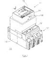
- Figure 1 is a perspective view of a remote controlled circuit breaker according to the invention.
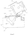
- FIG. 2 represents a schematic sectional view along line 2-2 of FIG. 1.
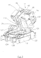
- FIG. 3 shows a perspective view of the remote control unit, shown in the tilted position on the upper part of the circuit breaker, the cover of the remote control unit being removed.
- Figures 4 and 5 are sectional views of Figure 3, respectively in the tilted position and in the mounted position of the remote control unit.
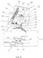
- Figures 6 to 8 are views similar to Figure 2, and illustrate the operation of the polarizing device, respectively in the open circuit breaker and disarmed remote control unit state, in the closed circuit breaker and armed remote control unit state, and in circuit breaker open and remote control unit armed.
- FIGS. 1 to 8 show a remote controlled circuit breaker 10 formed by the assembly of a remote control unit 11 with energy accumulation, and a circuit breaker 12 with molded insulating housing 13.
- the circuit breaker 12 is of the multipolar type containing a separable contact system 14 (FIGS. 6 and 8), the movable contact 16 of each pole is positioned in an orifice of the switching bar 18.
- the contact system 14 comprises, by way of example, a rotary double-contact contact bridge 16 cooperating with a pair of fixed contacts 38, 40, as described in document FR-A-2.622.347 of the applicant. It is understood that any other device, in particular a single cutout, can be used.
- the remote control unit 11 is formed by an adaptable module, attached to the front face of the circuit breaker 12 after removal of a faceplate.
- a second mechanism 42 arranged between two support plates 44, 46, extending in parallel (one with the other in the central part of the unit.
- the mechanism 42 is provided with '' an energy storage system 48 comprising a closing spring 50 mounted on a telescopic support 52 arranged between a fixed stop 54, and a finger 56 for transmitting a driving lever 58.
- Such an energy storage system 48 is described by way of example in document EP-A-222,645.
- the driving lever 58 is pivotally mounted on an axis 60 integral with the plates 44, 46, and is equipped, opposite the axis 60, with a cleat 62 for driving intended to come into engagement with the lever 24 to ensure closing the contacts 38, 40, 16 of the circuit breaker 12.
- the mechanism 42 further comprises a reset cam 64 mounted on a transverse transmission shaft 66 extending perpendicularly to the plates 44, 46 and to the driving lever 58.
- the cam resetting 64 cooperates with a roller 68 mounted for free rotation on the driving lever 58.
- the profile of the cam 64 has a first sector 70 for arming the closing spring, and a second sector 72 for releasing the roller 68 allowing movement of abrupt pivoting of the driving lever 58 clockwise under the expansion action of the closing spring 50.
- the second mechanism 42 is interposed between a geared motor member 74, and a manual emergency control 76 (FIG. 3).
- the reset cam 64 is provided with a third bearing surface 104 arranged between the first sector 70 and the second sector 72 for the stable maintenance of the roller 68 in the armed position of the second remote control mechanism 42.
- the second mechanism 42 is equipped with a first control button 94 for closing and a second control button 106 for opening, the latter cooperating with a push button 108 for triggering the attachment 36 of the first mechanism 20.
- the push button 108 is interposed between the half-moon of the attachment 36 and the lower end of the push button 106.
- crank pin 24 of the circuit breaker is engaged in a drawer 110 mounted in free translation in rectilinear slides 112 of the two plates 44, 46.
- the drawer 110 is moved by the cleat 62 of the driving lever 58 between the open and closed positions of the pin 24.
- the remote control unit 11 is pivotally mounted on a transverse axis 120 of a sole 122, which is fixed to the front face of the circuit breaker 12 after removal of the faceplate.
- the sole 122 has a central opening 124 for the passage of the lever. 24, and lateral openings 126 for accessing the compartments for housing the auxiliary blocks of the circuit breaker 12.
- the spacing between the two parallel plates 44, 46 of the second mechanism 42 of the tilting remote control unit 11 corresponds to that of the pair of fixed plates 128, 130 of the first mechanism 20.
- the two plates 44 and 128 on the left are coplanar, as are the two plates 46 and 130 on the right (the latter not being shown in the figures).
- a first anchoring element 132 intended to cooperate with a second anchoring element 134 conjugate provided at the upper part of each plate 128, 130 of the first mechanism 20 (figure 4).
- the first anchoring element 132 is formed by a female part, for example a notch which engages at the end of tilting stroke of the remote control unit 11 on a male part, in particular a projecting tooth of the second anchoring element 134 ( figure 5). It is clear that the male and female parts of the anchoring elements 132, 134 can be reversed on the corresponding plates.
- the tooth of the second anchoring element 134 projects from the front face of the circuit breaker.
- the engagement of the anchoring elements 132, 134 makes it possible to adjust the remote control unit 11 on the circuit breaker 12 according to the manufacturing tolerances of the parts of the two mechanisms 20, 42. This results in precise positioning and centering of the second mechanism 42 on the first mechanism 20, as well as an improvement in the chain of mounting dimensions.
- the tilting of the remote control unit 11 from the mounted position ( Figure 5) to the separated position ( Figure 4) allows direct access to the connection terminal block 127 as well as to the various compartments of the circuit breaker auxiliaries 12 through the openings 126 of the sole 122.
- This accessibility facilitates the interchangeability of the auxiliaries, comprising in particular a block of contacts signaling CAOF of the position of the contacts, a block of signal fault SD, and auxiliary trip units with undervoltage MN, with current emission MX.
- the second mechanism 42 is designed in such a way that the adaptation of the remote control unit 11 rocking on the circuit breaker 12 is only possible if the lever 24 and the second mechanism 42 are in agreement of states.
- the second mechanism 42 is provided with a keying device cooperating with the lever 24 and comprising a protrusion 136 integral with the drawer 110, and a status indicator 138 armed or disarmed from the energy storage system 48.
- the protrusion 136 is formed by a simple extension of the left side of the drawer 110.
- the indicator 138 comprises a polarization lever 140 articulated on an axis 142, and having at one of the ends an oblong groove 144, in which is engaged the axis of the roller 68 integral with the driving lever 58.
- the other end of the coding lever 140 is arranged in locking spout 146 capable of interfering with the top of the lever 24 for prohibit the installation of the remote control unit 11 in the event of a discrepancy between the lever 24, the drawer 110 and the lever 140 of the indicator 138.
- FIGS. 6 to 8 represent views illustrating different cases which may arise during the adaptation of the remote control unit 11 on the circuit breaker 12.
- the handle 24 of the circuit breaker 12 is in the right position corresponding to the open state of the contacts 16, 38, 40.
- the position of the polarizing lever 140 reflects that of the driving lever 58, and indicates l disarmed state of the energy storage system 48, in which the spring 50 is relaxed.
- the blocking spout 146 abuts against the lever 24 before the end of the tilting stroke, and thereby prevents the adaptation of the remote control unit 11.
- the lever 24 is in the left position, corresponding to the closed state of the contacts 16, 38, 40.
- the energy storage system 48 of the second mechanism 42 is armed following compression of the closing spring 50.
- the protrusion 136 abuts against the lever 24 during an attempt to tilt the remote control unit 11 on the circuit breaker 12.
- FIG. 8 shows a state matching case, in which the circuit breaker contacts 12 are in the open state, and the remote control unit 11 is armed. In this situation, the insertion of the handle 24 into the drawer 110 is possible, and the driving of the handle 24 by the second mechanism 42 of the remote control unit 11 becomes operational.
Landscapes
- Breakers (AREA)
Applications Claiming Priority (2)
| Application Number | Priority Date | Filing Date | Title |
|---|---|---|---|
| FR9301826 | 1993-02-16 | ||
| FR9301826A FR2701595B1 (fr) | 1993-02-16 | 1993-02-16 | Disjoncteur à bloc de télécommande adaptable. |
Publications (2)
| Publication Number | Publication Date |
|---|---|
| EP0612092A1 true EP0612092A1 (de) | 1994-08-24 |
| EP0612092B1 EP0612092B1 (de) | 1998-08-05 |
Family
ID=9444171
Family Applications (1)
| Application Number | Title | Priority Date | Filing Date |
|---|---|---|---|
| EP19940420034 Expired - Lifetime EP0612092B1 (de) | 1993-02-16 | 1994-02-02 | Schutzschalter mit anpassbarer Fernbetätigungseinheit |
Country Status (4)
| Country | Link |
|---|---|
| EP (1) | EP0612092B1 (de) |
| DE (1) | DE69412151T2 (de) |
| ES (1) | ES2120590T3 (de) |
| FR (1) | FR2701595B1 (de) |
Cited By (6)
| Publication number | Priority date | Publication date | Assignee | Title |
|---|---|---|---|---|
| EP0801411A3 (de) * | 1996-03-26 | 2000-10-04 | Structured Technology Corporation | Motormodul für in situ Montage auf Schutzschaltern |
| FR2815766A1 (fr) * | 2000-10-19 | 2002-04-26 | Gen Electric | Ensemble de montage d'un actionneur motorise sur un disjoncteur |
| EP1280177A1 (de) * | 2001-07-23 | 2003-01-29 | ABB Research Ltd. | Niederspannungschutzschalter |
| EP1280176A1 (de) * | 2001-07-23 | 2003-01-29 | ABB Research Ltd. | Niederspannungsschütz |
| CN105845469A (zh) * | 2015-01-30 | 2016-08-10 | 西门子公司 | 用于功率开关的远程驱动装置和用于驱动功率开关的设备 |
| CN113284757A (zh) * | 2021-04-14 | 2021-08-20 | 国网山东省电力公司淄博供电公司 | 一种10kV高压柜断路器首次送电远程合闸装置 |
Families Citing this family (4)
| Publication number | Priority date | Publication date | Assignee | Title |
|---|---|---|---|---|
| DE102005016544A1 (de) * | 2005-04-08 | 2006-10-12 | Abb Patent Gmbh | Modulfront für ein Schaltanlagenmodul, Schaltanlagenmodul und elektrische Schaltanlage |
| DE102012201854A1 (de) * | 2012-02-08 | 2013-08-08 | Siemens Aktiengesellschaft | Hilfsauslöser für ein elektrisches Schaltgerät sowie elektrisches Schaltgerät |
| CN104409293A (zh) * | 2014-12-12 | 2015-03-11 | 常熟市通润开关厂有限公司 | 一种多极断路器的辅助机构 |
| DE102015108629A1 (de) * | 2015-06-01 | 2016-12-01 | Eaton Electrical Ip Gmbh & Co. Kg | Mehrpoliges Schaltgerät in Leistenbauform mit verbesserter Abschaltung |
Citations (3)
| Publication number | Priority date | Publication date | Assignee | Title |
|---|---|---|---|---|
| GB995116A (en) * | 1962-11-08 | 1965-06-16 | Gen Electric | Improvements in electric switches or circuit breakers with motor operated mechanism |
| EP0038289A1 (de) * | 1980-04-15 | 1981-10-21 | Siemens Aktiengesellschaft | Kraftantrieb für elektrische Schaltgeräte |
| EP0427641A1 (de) * | 1989-11-06 | 1991-05-15 | Schneider Electric Sa | Fernsteuerungsvorrichtung für einen elektrischen Schutzschalter |
-
1993
- 1993-02-16 FR FR9301826A patent/FR2701595B1/fr not_active Expired - Fee Related
-
1994
- 1994-02-02 EP EP19940420034 patent/EP0612092B1/de not_active Expired - Lifetime
- 1994-02-02 ES ES94420034T patent/ES2120590T3/es not_active Expired - Lifetime
- 1994-02-02 DE DE1994612151 patent/DE69412151T2/de not_active Expired - Lifetime
Patent Citations (3)
| Publication number | Priority date | Publication date | Assignee | Title |
|---|---|---|---|---|
| GB995116A (en) * | 1962-11-08 | 1965-06-16 | Gen Electric | Improvements in electric switches or circuit breakers with motor operated mechanism |
| EP0038289A1 (de) * | 1980-04-15 | 1981-10-21 | Siemens Aktiengesellschaft | Kraftantrieb für elektrische Schaltgeräte |
| EP0427641A1 (de) * | 1989-11-06 | 1991-05-15 | Schneider Electric Sa | Fernsteuerungsvorrichtung für einen elektrischen Schutzschalter |
Cited By (7)
| Publication number | Priority date | Publication date | Assignee | Title |
|---|---|---|---|---|
| EP0801411A3 (de) * | 1996-03-26 | 2000-10-04 | Structured Technology Corporation | Motormodul für in situ Montage auf Schutzschaltern |
| FR2815766A1 (fr) * | 2000-10-19 | 2002-04-26 | Gen Electric | Ensemble de montage d'un actionneur motorise sur un disjoncteur |
| EP1280177A1 (de) * | 2001-07-23 | 2003-01-29 | ABB Research Ltd. | Niederspannungschutzschalter |
| EP1280176A1 (de) * | 2001-07-23 | 2003-01-29 | ABB Research Ltd. | Niederspannungsschütz |
| CN105845469A (zh) * | 2015-01-30 | 2016-08-10 | 西门子公司 | 用于功率开关的远程驱动装置和用于驱动功率开关的设备 |
| CN105845469B (zh) * | 2015-01-30 | 2019-02-12 | 西门子公司 | 用于功率开关的远程驱动装置和用于驱动功率开关的设备 |
| CN113284757A (zh) * | 2021-04-14 | 2021-08-20 | 国网山东省电力公司淄博供电公司 | 一种10kV高压柜断路器首次送电远程合闸装置 |
Also Published As
| Publication number | Publication date |
|---|---|
| FR2701595B1 (fr) | 1995-04-14 |
| FR2701595A1 (fr) | 1994-08-19 |
| ES2120590T3 (es) | 1998-11-01 |
| EP0612092B1 (de) | 1998-08-05 |
| DE69412151D1 (de) | 1998-09-10 |
| DE69412151T2 (de) | 1999-02-11 |
Similar Documents
| Publication | Publication Date | Title |
|---|---|---|
| EP0371887B1 (de) | Modulschützschalter mit Hilfsauslöseblock mit einer automatischen oder unabhängigen Wiedereinschaltung | |
| EP0633591B1 (de) | Betätigungsmechanismus für elektrischen Modulschutzschalter | |
| EP0331586B1 (de) | Betätigungsmechanismus eines Hilfsauslöseblocks für Modulschutzschalter | |
| EP0140761A2 (de) | Antriebsmechanismus für einen mehrpoligen Niederspannungs-Schutzschalter | |
| EP0612087A1 (de) | Fernbetätigter Schutzschalter mit Abtrennfunktion | |
| EP0394144A1 (de) | Hilfsschalter mit manueller Überprüfung für einen modularen Schutzschalter | |
| EP0935272B1 (de) | Auslösevorrichtung für Schutzschalter mit Signalisierung von Elektrische fehlern | |
| EP1542253B1 (de) | Anzeigeeinrichtung einer Auslöseeinrichtung eines elektrischen Schutzgeräts | |
| EP0326446B1 (de) | Steuer- und Signalhilfsschalter für mehrpoligen Modulschalter | |
| EP0612092B1 (de) | Schutzschalter mit anpassbarer Fernbetätigungseinheit | |
| EP0161946B1 (de) | An einen Schutzschalter ankuppelbare Zusatzeinheit | |
| EP0571258B1 (de) | Schutzschaltgerät | |
| CH686853A5 (fr) | Appareil interrupteur de protection accouplable à un module de commande et/ou à un module de signalisation. | |
| EP0161945A1 (de) | Fernschalthilfseinheit eines elektrischen Schutzschalters | |
| EP0951043B1 (de) | Hilfseinheit mit einer Anzeigevorrichtung zur Auslösung ausgerüstet mit Verschlüsselungsvorrichtung | |
| EP0951044B1 (de) | Hilfseinheit mit einer Anzeigevorrichtung anpassbar für einen Leistungschutzschalter | |
| FR3051593B1 (fr) | Dispositif de signalisation d'un defaut electrique dans un appareil de protection electrique, et appareil de protection electrique comportant un tel dispositif. | |
| FR2534414A1 (fr) | Interrupteur electrique sectionnable perfectionne | |
| FR2656155A1 (fr) | Auxiliaire d'adaptation pour interrupteur differentiel multipolaire. | |
| EP0472477B1 (de) | Betätigungsmechanismus mit Trennvorrichtung für elektrischen Schalter | |
| EP0602024B1 (de) | Betätigungsmechanismus für einen mehrpoligen Fehlerstromschutzschalter mit drehbarer Schaltwelle | |
| FR2659791A1 (fr) | Dispositif interrupteur auxiliaire pour un disjoncteur de protection de moteur a commande manuelle. | |
| FR2806520A1 (fr) | Dispositif de commande de disjoncteur |
Legal Events
| Date | Code | Title | Description |
|---|---|---|---|
| PUAI | Public reference made under article 153(3) epc to a published international application that has entered the european phase |
Free format text: ORIGINAL CODE: 0009012 |
|
| AK | Designated contracting states |
Kind code of ref document: A1 Designated state(s): DE ES GB IT |
|
| 17P | Request for examination filed |
Effective date: 19950110 |
|
| RAP1 | Party data changed (applicant data changed or rights of an application transferred) |
Owner name: SCHNEIDER ELECTRIC SA |
|
| 17Q | First examination report despatched |
Effective date: 19961025 |
|
| GRAG | Despatch of communication of intention to grant |
Free format text: ORIGINAL CODE: EPIDOS AGRA |
|
| GRAG | Despatch of communication of intention to grant |
Free format text: ORIGINAL CODE: EPIDOS AGRA |
|
| GRAH | Despatch of communication of intention to grant a patent |
Free format text: ORIGINAL CODE: EPIDOS IGRA |
|
| GRAH | Despatch of communication of intention to grant a patent |
Free format text: ORIGINAL CODE: EPIDOS IGRA |
|
| GRAA | (expected) grant |
Free format text: ORIGINAL CODE: 0009210 |
|
| AK | Designated contracting states |
Kind code of ref document: B1 Designated state(s): DE ES GB IT |
|
| REF | Corresponds to: |
Ref document number: 69412151 Country of ref document: DE Date of ref document: 19980910 |
|
| GBT | Gb: translation of ep patent filed (gb section 77(6)(a)/1977) |
Effective date: 19980911 |
|
| REG | Reference to a national code |
Ref country code: ES Ref legal event code: FG2A Ref document number: 2120590 Country of ref document: ES Kind code of ref document: T3 |
|
| PLBE | No opposition filed within time limit |
Free format text: ORIGINAL CODE: 0009261 |
|
| STAA | Information on the status of an ep patent application or granted ep patent |
Free format text: STATUS: NO OPPOSITION FILED WITHIN TIME LIMIT |
|
| 26N | No opposition filed | ||
| PGFP | Annual fee paid to national office [announced via postgrant information from national office to epo] |
Ref country code: GB Payment date: 20010131 Year of fee payment: 8 Ref country code: ES Payment date: 20010131 Year of fee payment: 8 |
|
| REG | Reference to a national code |
Ref country code: GB Ref legal event code: IF02 |
|
| PG25 | Lapsed in a contracting state [announced via postgrant information from national office to epo] |
Ref country code: GB Free format text: LAPSE BECAUSE OF NON-PAYMENT OF DUE FEES Effective date: 20020202 |
|
| PG25 | Lapsed in a contracting state [announced via postgrant information from national office to epo] |
Ref country code: ES Free format text: LAPSE BECAUSE OF NON-PAYMENT OF DUE FEES Effective date: 20020204 |
|
| GBPC | Gb: european patent ceased through non-payment of renewal fee |
Effective date: 20020202 |
|
| REG | Reference to a national code |
Ref country code: ES Ref legal event code: FD2A Effective date: 20031022 |
|
| PGFP | Annual fee paid to national office [announced via postgrant information from national office to epo] |
Ref country code: DE Payment date: 20120214 Year of fee payment: 19 |
|
| PGFP | Annual fee paid to national office [announced via postgrant information from national office to epo] |
Ref country code: IT Payment date: 20120215 Year of fee payment: 19 |
|
| REG | Reference to a national code |
Ref country code: DE Ref legal event code: R119 Ref document number: 69412151 Country of ref document: DE Effective date: 20130903 |
|
| PG25 | Lapsed in a contracting state [announced via postgrant information from national office to epo] |
Ref country code: DE Free format text: LAPSE BECAUSE OF NON-PAYMENT OF DUE FEES Effective date: 20130903 |