EP0613080B1 - Interface utilisateur graphique comprenant un espace de travail décalable et des fenêtres ancrables - Google Patents
Interface utilisateur graphique comprenant un espace de travail décalable et des fenêtres ancrables Download PDFInfo
- Publication number
- EP0613080B1 EP0613080B1 EP94300776A EP94300776A EP0613080B1 EP 0613080 B1 EP0613080 B1 EP 0613080B1 EP 94300776 A EP94300776 A EP 94300776A EP 94300776 A EP94300776 A EP 94300776A EP 0613080 B1 EP0613080 B1 EP 0613080B1
- Authority
- EP
- European Patent Office
- Prior art keywords
- desktop
- user
- window
- windows
- cursor
- Prior art date
- Legal status (The legal status is an assumption and is not a legal conclusion. Google has not performed a legal analysis and makes no representation as to the accuracy of the status listed.)
- Expired - Lifetime
Links
Images


Classifications
-
- G—PHYSICS
- G11—INFORMATION STORAGE
- G11B—INFORMATION STORAGE BASED ON RELATIVE MOVEMENT BETWEEN RECORD CARRIER AND TRANSDUCER
- G11B27/00—Editing; Indexing; Addressing; Timing or synchronising; Monitoring; Measuring tape travel
- G11B27/10—Indexing; Addressing; Timing or synchronising; Measuring tape travel
- G11B27/34—Indicating arrangements
-
- G—PHYSICS
- G06—COMPUTING OR CALCULATING; COUNTING
- G06F—ELECTRIC DIGITAL DATA PROCESSING
- G06F3/00—Input arrangements for transferring data to be processed into a form capable of being handled by the computer; Output arrangements for transferring data from processing unit to output unit, e.g. interface arrangements
- G06F3/14—Digital output to display device ; Cooperation and interconnection of the display device with other functional units
-
- G—PHYSICS
- G06—COMPUTING OR CALCULATING; COUNTING
- G06F—ELECTRIC DIGITAL DATA PROCESSING
- G06F3/00—Input arrangements for transferring data to be processed into a form capable of being handled by the computer; Output arrangements for transferring data from processing unit to output unit, e.g. interface arrangements
- G06F3/01—Input arrangements or combined input and output arrangements for interaction between user and computer
- G06F3/048—Interaction techniques based on graphical user interfaces [GUI]
- G06F3/0484—Interaction techniques based on graphical user interfaces [GUI] for the control of specific functions or operations, e.g. selecting or manipulating an object, an image or a displayed text element, setting a parameter value or selecting a range
- G06F3/0485—Scrolling or panning
-
- G—PHYSICS
- G11—INFORMATION STORAGE
- G11B—INFORMATION STORAGE BASED ON RELATIVE MOVEMENT BETWEEN RECORD CARRIER AND TRANSDUCER
- G11B27/00—Editing; Indexing; Addressing; Timing or synchronising; Monitoring; Measuring tape travel
- G11B27/02—Editing, e.g. varying the order of information signals recorded on, or reproduced from, record carriers
- G11B27/031—Electronic editing of digitised analogue information signals, e.g. audio or video signals
- G11B27/034—Electronic editing of digitised analogue information signals, e.g. audio or video signals on discs
Definitions
- the present invention relates to apparatus and methods for displaying graphic information, and more particularly, the present invention relates to a computer controlled display system for displaying and manipulating overlapping windows of data on a desktop workspace.
- the window may, therefore, take the form of a control panel for the video tape recorder, which includes the controls of play, reverse, record and the like. Similarly, the window may provide an area on the display screen in which movies, takes, or particular scenes are displayed for the user to edit.
- the display screen provides only a limited size workspace in which to operate on the windows.
- windows corresponding to resource such as video tape recorders, music synthesizers, audio tape recorders and music mixers may be opened and operating concurrently on the display.
- the workspace (known as the "desktop") which is available to the user may become cluttered and confusing to operate.
- the user may be required to frequently move windows in the workspace to make room for other windows to be opened, or alter the priority in which the windows are displayed and overlap one another to gain access to a desired window.
- the present invention provides a method and apparatus for increasing the usable workspace area in a window-based graphic user interface.
- the present invention provides a real and a virtual desktop comprising the entire workspace, and the ability of the user to pan horizontally across the entire area in a contiguous fashion.
- a computer display system including a central processing unit (CPU) coupled to a display having a display screen, such that data is displayed on said display screen in a plurality of windows, comprising:
- the present invention provides apparatus and methods for use in computer display systems, and in particular, display systems having object-oriented graphic user interfaces with overlapping windows.
- a display system including at least one central processing unit (CPU) is coupled through appropriate input/output (I/O) circuitry to input devices, such as a cursor control device.
- the CPU is further coupled to a hard disk drive for the storage of programs and data, and is coupled to a network through which the CPU may communicate with a variety of system resources such as editors, music synthesizers, graphic generators, and the like.
- the CPU is also coupled to a display device on which the present invention's users interface is displayed. Utilizing the teachings of the present invention, a "real" and a "virtual" workspace is defined comprising the entire desktop available to the user.
- the real workspace constitutes that portion of the desktop visible to the user on the display at any one time.
- the virtual workspace comprises a predefined extension of the screen area of the display which is also available for use by the user.
- the virtual workspace constitutes that portion of the desktop which is not visible to the user at any one time.
- the real and virtual workspaces comprise the entire desktop available to the user for opening and manipulating windows in the display system.
- windows may be selectively affixed to the desktop.
- a user may pan horizontally over the desktop (both real and virtual). If a window has been affixed to the desktop, the window maintains it position relative to the desk top, and appears to move relative to the user. If the window is not affixed to the desktop, it appears to "float" above the desktop and remains fixed relative to the user as the desktop is panned.
- the operations are machine operations performed in conjunction with a human operator.
- Useful machines for performing the operations of the present invention include general purpose digital computers or other similar devices.
- the present invention relates to method steps for operating a computer and processing electrical or other physical signals to generate other desired physical signals.
- the present invention also relates to apparatus for performing these operations.
- This apparatus may be specially constructed for the required purposes, or it may comprise a general purpose computer selectively activated or reconfigured by a computer program stored in the computer.
- the algorithms, methods and apparatus presented herein are not inherently related to any particular computer.
- various general purpose machines may be used with programs in accordance with the teachings herein, or it may prove more convenient to construct more specialised apparatus to perform the required method steps.
- the required structure for a variety of these machines will appear from the description given below.
- Machines which may perform the functions of the present invention include those manufactured by Sony Corporation of America, as well s other manufacturers of computer systems.
- the present invention discloses apparatus and methods for displaying graphic or other information in a window-based system on a computer display.
- numerous specific details are set forth such as computer system configurations, window elements, icons, desktop sizes, metaphors, window configurations and arrangements, etc. in order to provide a thorough understanding of the present invention.
- the present invention may be practised without these specific details.
- well known circuits, structures and the like are not described in detail so as not to obscure the present invention unnecessarily.
- the computer system includes a computer 20 which comprises four major components.
- the first of these is an input/output (I/O) circuit 22, which is used to communicate information in appropriately structured form to and from other portions of the computer 20.
- computer 20 includes a central processing unit (CPU) 24 coupled to the I/O circuit 22 and to a memory 26.
- CPU central processing unit
- a keyboard 30 for inputting data and commands into computer 20 through the I/O circuit 22, as is well known.
- a CD ROM 34 is coupled to the I/O circuit 22 for providing additional programming capacity to the system illustrated in Figure 1. It will be appreciated that additional devices may be coupled to the computer 20 for storing data, such as magnetic tape drives, buffer memory devices, and the like.
- a network interface 36 is coupled to both the memory 26 and the I/O circuit 22, to permit the computer 20 to communicate along a network 38 which is coupled to other system resources. For example, in a video editing environment, the computer 20 may be coupled over the network 38 to a video tape recorder 40, a music synthesizer 42, an audio tape recorder 44, and, special effects resource 46, as shown.
- a display monitor 50 is coupled to the computer 20 through the I/O circuit 22. Any well know variety of cathode ray tube (CRT), liquid crystal or other displays may be utilized as display 50.
- a cursor control device 52 includes switches 54 and 56 for signalling the CPU 24 in accordance with the teachings of the present invention. Cursor control device 52 (commonly referred to as a "mouse") permits a user to select various command modes, modify graphic data, and input other data utilizing switches 56 and 54. More particularly, the cursor control device 52 permits a user to selectively position a cursor 58 at any desired location on a display screen 60 of the display 50.
- the cursor 58 is disposed with a window 65 in the present invention's graphic user interface, to be described more fully below.
- the present invention's window-based user interface is generated and displayed using software stored in either memories 26,32 or CD ROM 34, and executed by the CPU 24.
- cursor control 52 utilizes well known apparatus and methods for signalling CPU 24 of positional changes or cursor 58 by movement of the cursor control over a surface.
- cursor control devices may be utilized by the present invention, including other control devices such as mechanical mice, trackballs, joy sticks, graphic tablets, other keyboard inputs and the like.
- the cursor control 52 in Figure 1 is intended to encompass all such equivalent devices.
- the cursor control device 52 and the equivalents thereof are collectively referred to a "mouse".
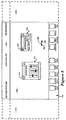
- the display screen 60 of the display 50 is shown in additional detail. Illustrated within the display 60, is a graphic user interface which includes a working area 100, a title bar 102 and a function bar 104, as illustrated.
- the function bar 104 includes a plurality of button functions which may be selected by the user, including a system setup function 106, a production log 108, a device controller 110, mast lists 112, edit control 114, edit bins 116, an audio mixer 188, special effects 120, a view source function 122, tool functions 124 and a production directory 126.
- the functions illustrated in Figure 2 are representative of a broad category of functions which may be utilized by the present invention.
- the present invention is illustrated with reference to a video edit graphic user interface, it will be appreciated that numerous functions may be applicable for use in conjunction with the present invention in other systems beyond that of video editing.
- the working area 100 comprises the "real" workspace of the display screen 60 which is visible to the user.
- the working area 100 is defined by a length 130 and width 132.
- the working area 100 comprises the real desktop space in which the user may operate on the functions selected from the function bar 104.
- a cursor 136 is provided which is controlled by using cursor control device 52, as previously described with respect to Figure 1, and discussed more fully below.
- a "virtual" workspace is also defined which includes areas 140 and 145 in Figure 2.
- the "desktop" available to a user comprises the combined length of the real and virtual working areas and is defined by length 150 and the width 132, as shown in Figure 2. Accordingly, the total workspace available in the desktop metaphor to the user of the present invention is the combined areas 100, 140 and 145.
- the virtual and real workspaces dynamically change. Therefore, for purposes of this specification, the real workspace constitutes that portion of the desktop visible to the user, and the virtual workspace constitutes that portion of the desktop which is not visible to the user at any one time.
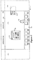
- cursor 136 includes a left arrowhead 165 and a right arrowhead 168.
- the workspace comprising the virtual workspaces 140 and 145 and real workspace 100, may be panned left or right by depressing an appropriate switch 54 or 56 on the cursor control device 52.
- the depression of left switch 56 results in the workspace being panned horizontally to the left and in the direction of the arrowhead 165.
- the depression of switch 54 results in the workspace panning right in the direction of arrowhead 168, as will be illustrated.
- a button function such as system setup 106 may be selected by placing cursor 136 over a portion of the function on the function bar 104 and momentarily clicking either switch 54 or 56 on the cursor control device 52.
- the movement of the cursor 136 over the function bar 104 results in a modification of the visual appearance of the cursor to that of a single arrow. (See cursor 58 in Figure 1).
- the movement of the cursor 136 into the working area 100 results in the modification of the visual appearance of the cursor once again, such that the cursor 136 appears as shown in Figure 2.
- System setup window 170 includes a drag bar 175 for selectively moving the window 170 over the working area 100.
- the cursor 136 is placed over a portion of bar 175, and a switch (either switch 54 or 56) on cursor control device 52 is depressed.
- the window 170 may then be selectively dragged to any location within the working area 100 and positioned for the convenience of the user.
- window 170 further includes a close box 180 which may be activated to close window 170 and redisplay the button function on the function bar 104.
- the window 170 may be closed by placing the cursor 136 over a portion of box 180 and momentarily depressing ("clicking") a switch on cursor control device 52.
- the window may comprise the control panel of the video editing device, such as an audio mixer, video tape recorder or the like, or may include areas in which text, graphics, or moves (such as for example, various scenes and takes) are displayed. Accordingly, it will be appreciated that the functions illustrated in the figures are for illustration only, and that in particular window characteristics shown are not to be considered limitations on the present invention.
- window 170 includes a floating window activation button 200.
- the button 200 in the presently preferred embodiment, includes the notation "UP" (or alternatively down “DN").
- the present invention permits a user to selectively set each opened window on the desktop (comprising both the real area 100 and virtual areas 145 and 140) to either float above the desktop, or appear to the user to be affixed to the desktop.
- each window upon selecting a function along the function bar 104, each window is opened (for example window 170) with the floating window activation button 200 selected by default in the "UP" (not affixed) configuration.
- window 170 "floats" above the desktop comprising the real working area 100 and virtual areas 145 and 140.
- the window 170 floats above the desktop such that it remains in the same relative position as viewed by the user regardless of which direction the desktop is panned.
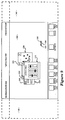
- switch 54 has been depressed by the user, such that the desktop has panned to the right in the direction of arrowhead 168. As shown, although the desktop has panned to the right, the window 170 remains stationary with respect to the user.
- window 170 is illustrated with the floating window activation button 200 in the down ("DN") position.
- the audio mix button function has been activated by a user, resulting in the display of the audio mix window 210.
- window 210 includes a floating window activation button 215 which is in the "UP" position, and thereby results in the window 210 floating above the working area 100 in a position fixed relative to the user.
- the user depresses switch 54 on the cursor control device 52, thereby panning the desktop to the right as viewed by the user (in the direction of arrow 168).
- panning the desktop to the right in the direction of arrow 168 results in the window 170 being obscured from view as it passes out of area 100 and into the virtual desktop 140 (shown for illustration in dashed lines).
- activation button 200 of the window 170 was selected by the user to be in the down ("DN") position, and accordingly, the window 170 moves relative to the user as if it is affixed to the desktop.
- window 170 pans with the desktop, whether to the right or to the left, as the desktop is panned by the user using the cursor control device 52.
- audio mix window 210 remains stationary in space relative to the user, such that it appears to "float" over the desktop. Since window 210 floats over the desktop, it does not move relative to the user as the desktop is panned right or left.
- window 170 is shown in Figure 6 in dashed lines, that the dashed lines are for illustration only, and that the present embodiment, those items illustrated in the figures in dashed lines are not visible to the user, since they fall outside of the real working area 100 of the desktop which comprises the screen 60.
- Figure 7 shows the panning left of the desktop by the user.
- the user depresses switch 56 on cursor control device 52 to initiate panning left (in direction of arrow 165 on cursor 136).
- window 210 remains stationary in space and floats over the desktop as a result of activation button 215 being in an "UP" position.
- window 170 has moved such tat it is partially visible in the real working area 100 as the desktop is panned left by the user.
- continuing to pan the desktop left in the direction of arrow 165 results in the window 170 appearing to traverse the real working area 100, and moving partially into the virtual desktop area 145 as the desktop is panned.
- window 210 in which floating window activation button 215 is in an "UP” position, and window 170 in which the activation button 200 has been selected to be in a down (“DN") position.
- window 230 has been opened in which the activation button 235 has been selected by the user to be in a down (“DN") position, thereby affixing it to the desktop.
- window 210 floats above the desktop, that it appears to be “closer” to the user and thereby overlays windows which have been affixed to the desktop by being placed in a down (“DN”) position (in the present example, windows 170 and 230).
- window 210 remains stationary in space relative to the user since the function 215 is in the UP (floating) position. Also illustrated in Figure 10 is the movement of windows 230 and 170 relative to the user as the desktop pans left. As shown, window 170 is only partially visible, with a portion of window 170 having entered the virtual workspace 145. Similarly, as shown in Figure 10, window 230 has passed behind the window 210 and is partially obscured by window 210.
- the desktop of the present invention includes the real working area 100 (real workspace) and virtual areas 140 and 145 (virtual workspace).
- the entire desktop comprising the graphic user interface of the present invention includes areas 100, 140 and 145 having an overall length identified in figure 11 as length 250.
- window 170 is set such that the floating window activation button function 200 is in an UP (floating) position.
- window 210 has been selected such that the activation button 2315 is in the down ("DN") position.
- window 230 is provided in which the activation button 235 has been selected by the user to be in the UP position.
- An additional window 300 is illustrated in which its activation button 310 is in down ("DN") position.
- a centre line 320 conceptually represents the centre line of the real working area 100, comprising display screen 60 as viewed by the user.
- panning the desktop to the right results in the system window maintaining its position relative to the centre line 320 and the user since the floating window activation function button 200 is in an UP (unaffixed) position.
- window 230 remains fixed relative to the user since its activation button 235 is in an UP position as well.
- window 210 moves with the desktop as a result of activation button 215 being in a down (affixed) position, as does window 300 as illustrated in Figure 11b.
- Windows 170 and 230 maintain their same relative position to the user and float above the desktop.
- Windows 210 and 300 being "affixed" to the desktop move with the desktop to the left, as shown in Figure 11c.
- the present invention as described provides an improved graphic user interface for use in a window-based display system. While the present invention has been described with reference to Figures 1 through 11, it will be appreciated that the figures are for illustration only, and do not limit the spirit and scope of the invention. For example, all of the figures may have, by necessity, used example windows having certain attributes and/or functions, it will be appreciated that the invention is not limited by the specific examples provided.
Landscapes
- Engineering & Computer Science (AREA)
- Theoretical Computer Science (AREA)
- General Engineering & Computer Science (AREA)
- Human Computer Interaction (AREA)
- Physics & Mathematics (AREA)
- General Physics & Mathematics (AREA)
- Multimedia (AREA)
- Digital Computer Display Output (AREA)
- User Interface Of Digital Computer (AREA)
Claims (33)
- Système d'affichage d'ordinateur incluant une unité centrale de traitement (CPU) (24) couplée à un affichage (50) comportant un écran d'affichage (60) de telle sorte que des données soient affichées sur ledit écran d'affichage dans une pluralité de fenêtres, comprenant:un moyen de génération d'interface utilisateur couplé à ladite CPU pour afficher lesdites données dans lesdites fenêtres, ledit moyen de génération d'interface utilisateur générant et affichant une interface utilisateur incluant un bureau comportant une partie visible (100) et une partie virtuelle (140, 145), dans lequel ladite partie visible (100) correspond à la partie dudit bureau présentement visible sur ledit écran d'affichage (60), ladite partie virtuelle correspond à la partie dudit bureau présentement non visible pour ledit utilisateur sur ledit écran d'affichage ;un moyen de panoramique (52, 30) couplé à ladite CPU pour réaliser de façon sélective un panoramique dudit bureau suivant au moins deux directions de telle sorte que ledit bureau réalise un panoramique suivant une direction choisie par l'utilisateur et que la partie dudit bureau dans ladite partie visible soit affichée pour ledit utilisateur, caractérisé en ce que lesdites fenêtres affichées sur ledit bureau incluent un moyen de fixation (200) pour fixer de façon sélective au moins l'une desdites fenêtres (170) audit bureau de telle sorte que si une fenêtre (170) est fixée audit bureau, ladite fenêtre (170) se déplace avec ledit bureau suivant la direction selon laquelle ledit bureau réalise un panoramique et reste stationnaire par rapport audit bureau.
- Système d'affichage d'ordinateur selon la revendication 1, dans lequel, dans l'éventualité où ladite fenêtre (170) n'est pas fixée audit bureau, ladite fenêtre reste stationnaire par rapport audit utilisateur de telle sorte que ladite fenêtre non fixée apparaít audit utilisateur comme flottant au-dessus dudit bureau lorsque ledit bureau réalise un panoramique.
- Système d'affichage d'ordinateur selon la revendication 2, dans lequel ledit moyen de panoramique inclut un dispositif de commande de curseur (52) couplé à ladite CPU et activable par ledit utilisateur.
- Système d'affichage d'ordinateur selon la revendication 2 ou 3, dans lequel ledit moyen de fixation (200) inclut un bouton d'activation de fenêtre flottante dans chacune desdites fenêtres (170) affichées sur ledit affichage présentant deux états, un premier état correspondant à un état fixé et un second état correspondant audit état non fixé.
- Système d'affichage d'ordinateur selon la revendication 4, dans lequel ledit bouton d'activation (200) affiche la notation DN si ladite fonction a été placée dans ledit état fixé.
- Système d'affichage d'ordinateur selon la revendication 5, dans lequel ledit bouton d'activation (200) affiche la notation UP si ladite fonction a été placée dans ledit état non fixé.
- Système d'affichage d'ordinateur selon l'une quelconque des revendications 2 à 4, incluant en outre une barre de fonctions (104) sur ledit écran d'affichage sur laquelle sont affichées une pluralité de fonctions sélectionnables par ledit utilisateur.
- Système d'affichage d'ordinateur selon la revendication 7, dans lequel ladite barre de fonctions (104) est disposée horizontalement le long de la partie inférieure dudit écran d'affichage.
- Système d'affichage d'ordinateur selon la revendication 8, incluant en outre une barre de titres (102) disposée horizontalement au sommet dudit écran d'affichage.
- Système d'affichage d'ordinateur selon la revendication 9, dans lequel ladite barre de fonctions (104) reste stationnaire par rapport audit utilisateur.
- Système d'affichage d'ordinateur selon la revendication 9, dans lequel ladite barre de titres réalise un panoramique avec ledit bureau.
- Système d'affichage d'ordinateur selon l'une quelconque des revendications 2 à 11, dans lequel, dans l'éventualité où lesdites fenêtres se chevauchent les unes les autres sur ledit bureau, des fenêtres (170) non fixées audit bureau apparaissent audit utilisateur comme flottant au-dessus de fenêtres (210) qui sont fixées audit bureau.
- Système d'affichage d'ordinateur selon la revendication 12, dans lequel ledit panoramique est horizontal.
- Système d'affichage d'ordinateur selon la revendication 3, dans lequel ledit bureau inclut en outre un curseur (136) affiché sur ledit écran d'affichage et commandé par ledit dispositif de commande de curseur (52), ledit curseur présentant la forme d'une flèche incluant un corps et deux têtes de flèche opposées, l'une (165) desdites têtes de flèche pointant vers la gauche et l'autre tête de flèche (168) pointant vers la droite par rapport audit utilisateur qui visualise ledit affichage, lesdites têtes de flèche correspondant à des directions de panoramique dudit bureau.
- Système d'affichage d'ordinateur selon la revendication 14, dans lequel ledit dispositif de commande de curseur inclut au moins deux commutateurs (54, 56) couplés à ladite CPU, lesdits commutateurs correspondant auxdites directions de panoramique.
- Système d'affichage d'ordinateur selon la revendication 15, dans lequel, si ledit curseur est placé par ledit utilisateur qui utilise ledit dispositif de commande de curseur au-dessus de l'une desdites fenêtres affichées sur ledit bureau, ladite CPU modifie la forme dudit curseur.
- Système d'affichage d'ordinateur selon la revendication 16, dans lequel ledit curseur modifié présente la forme d'une flèche comportant seulement une unique tête de flèche.
- Procédé permettant d'augmenter l'espace de travail utilisable pour un utilisateur dans un système d'affichage d'ordinateur incluant une unité centrale de traitement (CPU) (24) couplée à un affichage (50) comportant un écran d'affichage (60) de telle sorte que des données soient affichées sur ledit écran d'affichage dans une pluralité de fenêtres, comprenant les étapes de:génération et affichage d'une interface utilisateur incluant un bureau comportant une partie visible (100) et une partie virtuelle (150, 145), dans lequel ladite partie visible (100) correspond à la partie dudit bureau présentement visible sur ledit écran d'affichage et ladite partie virtuelle (140, 145) correspond à la partie dudit bureau présentement non visible pour ledit utilisateur sur ledit écran d'affichage;soumission dudit bureau à un panoramique suivant au moins deux directions de telle sorte que ledit bureau réalise un panoramique suivant une direction sélectionnée par un utilisateur et que la partie dudit bureau dans ladite partie visible soit affichée pour ledit utilisateur; etfixation de façon sélective d'au moins l'une (170) desdites fenêtres audit bureau de telle sorte que si une fenêtre est fixée audit bureau, ladite fenêtre (170) se déplace avec ledit bureau suivant la direction selon laquelle ledit bureau est soumis à un panoramique et reste stationnaire par rapport audit bureau, caractérisé en ce que, dans l'éventualité où ladite fenêtre (170) n'est pas fixée audit bureau, ladite fenêtre reste stationnaire par rapport audit utilisateur de telle sorte que ladite fenêtre non fixée apparaít audit utilisateur comme flottant au-dessusdudit bureau lorsque ledit bureau est soumis à un panoramique.
- Procédé selon la revendication 18, dans lequel ledit utilisateur utilise un dispositif de commande de curseur (52) couplé à ladite CPU et actionnable par ledit utilisateur pour soumettre à un panoramique ledit bureau.
- Procédé selon la revendication 18, dans lequel chacune desdites fenêtres inclut un bouton d'activation de fenêtre flottante comportant deux états, un premier état correspondant à un état fixé et un second état correspondant audit état non fixé.
- Procédé selon la revendication 20, dans lequel ledit bouton d'activation affiche la notation DN si ladite fonction a été placée dans ledit état fixé.
- Procédé selon la revendication 20, dans lequel ledit bouton d'activation affiche la notation UP si ladite fonction a été placée dans ledit état non fixé.
- Procédé selon la revendication 18, incluant en outre une barre de fonctions (104) sur ledit écran d'affichage d'ordinateur sur laquelle sont affichées une pluralité de fonctions sélectionnables par ledit utilisateur.
- Procédé selon la revendication 23, dans lequel ladite barre de fonctions (104) est disposée horizontalement le long de la partie inférieure dudit écran d'affichage.
- Procédé selon la revendication 24, incluant en outre une barre de titres (102) disposée horizontalement sur le sommet dudit écran d'affichage d'ordinateur.
- Procédé selon la revendication 25, dans lequel ladite barre de fonctions (104) reste stationnaire par rapport audit utilisateur.
- Procédé selon la revendication 25, dans lequel ladite barre de titres réalise un panoramique avec ledit bureau.
- Procédé selon la revendication 18, dans lequel, dans l'éventualité où lesdites fenêtres se chevauchent les unes les autres sur ledit bureau, des fenêtres (107) non fixées audit bureau apparaissent audit utilisateur comme flottant au-dessus de fenêtres (200) qui sont fixées audit bureau.
- Procédé selon la revendication 28, dans lequel ledit panoramique est horizontal.
- Procédé selon la revendication 19, dans lequel ledit bureau inclut en outre un curseur (136) affiché sur ledit écran d'affichage et commandé par ledit dispositif de commande de curseur, ledit curseur présentant la forme d'une flèche incluant un corps et deux têtes de flèche opposées, l'une (165) desdites têtes de flèche pointant vers la gauche et l'autre tête de flèche (168) pointant vers la droite par rapport audit utilisateur qui visualise ledit affichage, lesdites têtes de flèche correspondant à des directions de panoramique dudit bureau.
- Procédé selon la revendication 30, dans lequel ledit dispositif de commande de curseur inclut au moins deux commutateurs (54, 56) couplés à ladite CPU, lesdits commutateurs correspondant auxdites directions de panoramique.
- Procédé selon la revendication 31, dans lequel, si ledit curseur est placé par ledit utilisateur qui utilise ledit dispositif de commande de curseur au-dessus de l'une desdites fenêtres affichées sur ledit bureau, ladite CPU modifie la forme dudit curseur.
- Procédé selon la revendication 32, dans lequel ledit curseur modifié présente la forme d'une flèche comportant seulement une unique tête de flèche.
Applications Claiming Priority (2)
| Application Number | Priority Date | Filing Date | Title |
|---|---|---|---|
| US2187293A | 1993-02-24 | 1993-02-24 | |
| US21872 | 1993-02-24 |
Publications (3)
| Publication Number | Publication Date |
|---|---|
| EP0613080A2 EP0613080A2 (fr) | 1994-08-31 |
| EP0613080A3 EP0613080A3 (fr) | 1995-12-20 |
| EP0613080B1 true EP0613080B1 (fr) | 2000-09-13 |
Family
ID=21806607
Family Applications (1)
| Application Number | Title | Priority Date | Filing Date |
|---|---|---|---|
| EP94300776A Expired - Lifetime EP0613080B1 (fr) | 1993-02-24 | 1994-02-02 | Interface utilisateur graphique comprenant un espace de travail décalable et des fenêtres ancrables |
Country Status (4)
| Country | Link |
|---|---|
| EP (1) | EP0613080B1 (fr) |
| JP (1) | JPH06250811A (fr) |
| KR (1) | KR100324836B1 (fr) |
| DE (1) | DE69425842T2 (fr) |
Families Citing this family (25)
| Publication number | Priority date | Publication date | Assignee | Title |
|---|---|---|---|---|
| JP2519815B2 (ja) * | 1990-03-01 | 1996-07-31 | 三菱電機株式会社 | フォトマスク及びその製造方法 |
| US6078380A (en) * | 1991-10-08 | 2000-06-20 | Nikon Corporation | Projection exposure apparatus and method involving variation and correction of light intensity distributions, detection and control of imaging characteristics, and control of exposure |
| US5420417A (en) * | 1991-10-08 | 1995-05-30 | Nikon Corporation | Projection exposure apparatus with light distribution adjustment |
| JP3069417B2 (ja) * | 1991-11-21 | 2000-07-24 | シャープ株式会社 | 位相シフトマスクの検査方法 |
| JP3141471B2 (ja) * | 1991-12-25 | 2001-03-05 | 株式会社ニコン | ディスク媒体の製造方法、及び製造装置、並びに露光方法及び露光装置 |
| US5703675A (en) * | 1992-01-17 | 1997-12-30 | Nikon Corporation | Projection-exposing apparatus with deflecting grating member |
| JPH05217855A (ja) * | 1992-02-01 | 1993-08-27 | Nikon Corp | 露光用照明装置 |
| JP3075381B2 (ja) * | 1992-02-17 | 2000-08-14 | 株式会社ニコン | 投影露光装置及び転写方法 |
| US6020950A (en) * | 1992-02-24 | 2000-02-01 | Nikon Corporation | Exposure method and projection exposure apparatus |
| JP3235029B2 (ja) * | 1992-03-06 | 2001-12-04 | 株式会社ニコン | 投影露光装置、及び投影露光方法 |
| JP2864915B2 (ja) * | 1992-12-07 | 1999-03-08 | 株式会社日立製作所 | 半導体装置の製造方法 |
| US6903723B1 (en) * | 1995-03-27 | 2005-06-07 | Donald K. Forest | Data entry method and apparatus |
| US6160536A (en) * | 1995-03-27 | 2000-12-12 | Forest; Donald K. | Dwell time indication method and apparatus |
| GB2332972B (en) * | 1995-03-27 | 1999-08-18 | Donald K Forest | Dwell time indicator |
| WO1999001838A2 (fr) * | 1997-07-03 | 1999-01-14 | Koninklijke Philips Electronics N.V. | Appareil et procede pour la creation et la commande d'un espace de travail virtuel d'un systeme de fenetrage |
| FR2798803A1 (fr) * | 1999-09-16 | 2001-03-23 | Antoine Vialle | Console de traitement d'effets speciaux |
| AU4264501A (en) | 2000-04-05 | 2001-10-15 | Sony United Kingdom Limited | Audio/video reproducing apparatus and method |
| GB2361098A (en) * | 2000-04-05 | 2001-10-10 | Sony Uk Ltd | Editing system and method using metadata |
| DE10246902A1 (de) * | 2002-10-08 | 2004-02-19 | Siemens Ag | Verwaltung von Visualisierungsbereichen in integrierten grafischen Benutzeroberflächen |
| EP1555599A1 (fr) * | 2004-01-19 | 2005-07-20 | Matsushita Electric Industrial Co., Ltd. | Positionnement fixe d'une aire d'affichage |
| US8276095B2 (en) * | 2004-02-20 | 2012-09-25 | Advanced Intellectual Property Group, Llc | System for and method of generating and navigating within a workspace of a computer application |
| KR100586982B1 (ko) | 2004-05-20 | 2006-06-08 | 삼성전자주식회사 | 디스플레이 시스템 및 그 가상 작업공간 관리방법 |
| KR101470543B1 (ko) * | 2008-02-15 | 2014-12-08 | 엘지전자 주식회사 | 터치스크린을 구비하는 휴대 단말기 및 그 동작 제어방법 |
| WO2014194314A1 (fr) * | 2013-05-31 | 2014-12-04 | Freedom Scientific, Inc. | Repères de pointage personnalisables basés sur un vecteur |
| CN113687902B (zh) * | 2021-08-30 | 2024-06-07 | 广州酷狗计算机科技有限公司 | 资源展示方法、装置、计算机设备及存储介质 |
-
1994
- 1994-02-02 DE DE69425842T patent/DE69425842T2/de not_active Expired - Fee Related
- 1994-02-02 EP EP94300776A patent/EP0613080B1/fr not_active Expired - Lifetime
- 1994-02-22 JP JP6024480A patent/JPH06250811A/ja active Pending
- 1994-02-24 KR KR1019940003313A patent/KR100324836B1/ko not_active Expired - Fee Related
Also Published As
| Publication number | Publication date |
|---|---|
| DE69425842T2 (de) | 2001-03-29 |
| JPH06250811A (ja) | 1994-09-09 |
| KR940020206A (ko) | 1994-09-15 |
| KR100324836B1 (ko) | 2002-06-20 |
| DE69425842D1 (de) | 2000-10-19 |
| EP0613080A3 (fr) | 1995-12-20 |
| EP0613080A2 (fr) | 1994-08-31 |
Similar Documents
| Publication | Publication Date | Title |
|---|---|---|
| EP0613080B1 (fr) | Interface utilisateur graphique comprenant un espace de travail décalable et des fenêtres ancrables | |
| US5874952A (en) | Method and apparatus for improved graphical user interface with function icons | |
| US5155806A (en) | Method and apparatus for displaying context sensitive help information on a display | |
| US6377285B1 (en) | Zooming space-grid for graphical user interface | |
| US5572649A (en) | Process for dynamically switching between a single top level window and multiple top level windows | |
| US5630042A (en) | Method and apparatus for providing collection browsers | |
| US5544300A (en) | User interface for dynamically converting between a single top level window and multiple top level windows | |
| US5339393A (en) | Graphical user interface for displaying available source material for editing | |
| US5157768A (en) | Method and apparatus for displaying context sensitive help information on a display | |
| US7490297B2 (en) | Window scroll bar | |
| US5986657A (en) | Method and apparatus for incorporating expandable and collapsible options in a graphical user interface | |
| US6404443B1 (en) | Three-dimensional graphical user interface for managing screen objects | |
| US5704050A (en) | Snap control for relocating elements of a graphical user interface | |
| US5602996A (en) | Method and apparatus for determining window order when one of multiple displayed windows is selected | |
| JP4602487B2 (ja) | グラフィックオブジェクトのグループを作成し操作するための方法及びコンピュータ制御グラフィックディスプレイシステム | |
| US5148154A (en) | Multi-dimensional user interface | |
| KR950014982B1 (ko) | 데이타 처리 시스템의 디스플레이 화면을 구별되는 영역으로 분할하기 위한 시스템 및 그 방법 | |
| JP2659917B2 (ja) | グラフィック操作方法及び装置、グラフィック・ユーザ・インターフェースを提供する方法並びにユーザ操作可能多重オーバラップ・オブジェクトの選択された1つへのアクセスを提供する装置 | |
| US20040021694A1 (en) | Mode activated scrolling | |
| EP0192927A2 (fr) | Méthode d'édition graphique d'objets dans un système de dessin graphique interactif utilisant des actions d'édition implicites | |
| US20080059893A1 (en) | Using a zooming effect to provide additional display space for managing applications | |
| JPH0619666A (ja) | 制御プログラム及び少なくとも1つの従属プログラムの使用性を向上させる方法及びコンピュータ制御式表示システム | |
| US5802334A (en) | Method for displaying object oriented class information and content information | |
| EP0613145A2 (fr) | Interface utilisateur graphique pour fichiers de cartes avec représentation visuelle de données vidéo | |
| US5995984A (en) | Apparatus and method for zoom-in entry of an element in a table |
Legal Events
| Date | Code | Title | Description |
|---|---|---|---|
| PUAI | Public reference made under article 153(3) epc to a published international application that has entered the european phase |
Free format text: ORIGINAL CODE: 0009012 |
|
| AK | Designated contracting states |
Kind code of ref document: A2 Designated state(s): DE FR GB NL |
|
| PUAL | Search report despatched |
Free format text: ORIGINAL CODE: 0009013 |
|
| AK | Designated contracting states |
Kind code of ref document: A3 Designated state(s): DE FR GB NL |
|
| 17P | Request for examination filed |
Effective date: 19960517 |
|
| 17Q | First examination report despatched |
Effective date: 19990812 |
|
| GRAG | Despatch of communication of intention to grant |
Free format text: ORIGINAL CODE: EPIDOS AGRA |
|
| RTI1 | Title (correction) |
Free format text: GRAPHICAL USER INTERFACE INCORPORATING A PANNING WORKSPACE WITH MEANS FOR AFFIXING WINDOWS |
|
| GRAG | Despatch of communication of intention to grant |
Free format text: ORIGINAL CODE: EPIDOS AGRA |
|
| GRAH | Despatch of communication of intention to grant a patent |
Free format text: ORIGINAL CODE: EPIDOS IGRA |
|
| GRAH | Despatch of communication of intention to grant a patent |
Free format text: ORIGINAL CODE: EPIDOS IGRA |
|
| GRAA | (expected) grant |
Free format text: ORIGINAL CODE: 0009210 |
|
| AK | Designated contracting states |
Kind code of ref document: B1 Designated state(s): DE FR GB NL |
|
| REF | Corresponds to: |
Ref document number: 69425842 Country of ref document: DE Date of ref document: 20001019 |
|
| ET | Fr: translation filed | ||
| PLBE | No opposition filed within time limit |
Free format text: ORIGINAL CODE: 0009261 |
|
| STAA | Information on the status of an ep patent application or granted ep patent |
Free format text: STATUS: NO OPPOSITION FILED WITHIN TIME LIMIT |
|
| 26N | No opposition filed | ||
| REG | Reference to a national code |
Ref country code: GB Ref legal event code: IF02 |
|
| PGFP | Annual fee paid to national office [announced via postgrant information from national office to epo] |
Ref country code: NL Payment date: 20090203 Year of fee payment: 16 Ref country code: DE Payment date: 20090129 Year of fee payment: 16 |
|
| PGFP | Annual fee paid to national office [announced via postgrant information from national office to epo] |
Ref country code: GB Payment date: 20090128 Year of fee payment: 16 |
|
| PGFP | Annual fee paid to national office [announced via postgrant information from national office to epo] |
Ref country code: FR Payment date: 20090213 Year of fee payment: 16 |
|
| REG | Reference to a national code |
Ref country code: NL Ref legal event code: V1 Effective date: 20100901 |
|
| GBPC | Gb: european patent ceased through non-payment of renewal fee |
Effective date: 20100202 |
|
| REG | Reference to a national code |
Ref country code: FR Ref legal event code: ST Effective date: 20101029 |
|
| PG25 | Lapsed in a contracting state [announced via postgrant information from national office to epo] |
Ref country code: NL Free format text: LAPSE BECAUSE OF NON-PAYMENT OF DUE FEES Effective date: 20100901 Ref country code: FR Free format text: LAPSE BECAUSE OF NON-PAYMENT OF DUE FEES Effective date: 20100301 |
|
| PG25 | Lapsed in a contracting state [announced via postgrant information from national office to epo] |
Ref country code: DE Free format text: LAPSE BECAUSE OF NON-PAYMENT OF DUE FEES Effective date: 20100901 |
|
| PG25 | Lapsed in a contracting state [announced via postgrant information from national office to epo] |
Ref country code: GB Free format text: LAPSE BECAUSE OF NON-PAYMENT OF DUE FEES Effective date: 20100202 |