EP0613301A2 - Videodatenkompressor zur Minimierung der Fehlerfortpflanzung - Google Patents
Videodatenkompressor zur Minimierung der Fehlerfortpflanzung Download PDFInfo
- Publication number
- EP0613301A2 EP0613301A2 EP94102582A EP94102582A EP0613301A2 EP 0613301 A2 EP0613301 A2 EP 0613301A2 EP 94102582 A EP94102582 A EP 94102582A EP 94102582 A EP94102582 A EP 94102582A EP 0613301 A2 EP0613301 A2 EP 0613301A2
- Authority
- EP
- European Patent Office
- Prior art keywords
- data
- shuffling
- compressor
- video data
- predetermined
- Prior art date
- Legal status (The legal status is an assumption and is not a legal conclusion. Google has not performed a legal analysis and makes no representation as to the accuracy of the status listed.)
- Withdrawn
Links
- 239000012141 concentrate Substances 0.000 abstract description 4
- 238000010586 diagram Methods 0.000 description 9
- 238000006243 chemical reaction Methods 0.000 description 8
- 238000013139 quantization Methods 0.000 description 7
- 238000000034 method Methods 0.000 description 5
- 230000005540 biological transmission Effects 0.000 description 3
- 230000003287 optical effect Effects 0.000 description 3
- 230000000644 propagated effect Effects 0.000 description 3
- 230000004075 alteration Effects 0.000 description 1
- 230000003321 amplification Effects 0.000 description 1
- 238000003491 array Methods 0.000 description 1
- 239000002131 composite material Substances 0.000 description 1
- 238000007906 compression Methods 0.000 description 1
- 230000006835 compression Effects 0.000 description 1
- 230000010485 coping Effects 0.000 description 1
- 238000013144 data compression Methods 0.000 description 1
- 238000003199 nucleic acid amplification method Methods 0.000 description 1
- 230000002093 peripheral effect Effects 0.000 description 1
- 238000000926 separation method Methods 0.000 description 1
Images


Classifications
-
- H—ELECTRICITY
- H04—ELECTRIC COMMUNICATION TECHNIQUE
- H04N—PICTORIAL COMMUNICATION, e.g. TELEVISION
- H04N19/00—Methods or arrangements for coding, decoding, compressing or decompressing digital video signals
- H04N19/85—Methods or arrangements for coding, decoding, compressing or decompressing digital video signals using pre-processing or post-processing specially adapted for video compression
- H04N19/89—Methods or arrangements for coding, decoding, compressing or decompressing digital video signals using pre-processing or post-processing specially adapted for video compression involving methods or arrangements for detection of transmission errors at the decoder
-
- H—ELECTRICITY
- H04—ELECTRIC COMMUNICATION TECHNIQUE
- H04N—PICTORIAL COMMUNICATION, e.g. TELEVISION
- H04N5/00—Details of television systems
- H04N5/76—Television signal recording
- H04N5/91—Television signal processing therefor
- H04N5/92—Transformation of the television signal for recording, e.g. modulation, frequency changing; Inverse transformation for playback
- H04N5/926—Transformation of the television signal for recording, e.g. modulation, frequency changing; Inverse transformation for playback by pulse code modulation
- H04N5/9261—Transformation of the television signal for recording, e.g. modulation, frequency changing; Inverse transformation for playback by pulse code modulation involving data reduction
- H04N5/9264—Transformation of the television signal for recording, e.g. modulation, frequency changing; Inverse transformation for playback by pulse code modulation involving data reduction using transform coding
-
- H—ELECTRICITY
- H04—ELECTRIC COMMUNICATION TECHNIQUE
- H04N—PICTORIAL COMMUNICATION, e.g. TELEVISION
- H04N5/00—Details of television systems
- H04N5/76—Television signal recording
- H04N5/91—Television signal processing therefor
- H04N5/93—Regeneration of the television signal or of selected parts thereof
- H04N5/94—Signal drop-out compensation
- H04N5/945—Signal drop-out compensation for signals recorded by pulse code modulation
Definitions
- the present invention relates to a video data compressor for compressing video data, and in particular, to a video data compressor connectible to a recording apparatus such as a digital video tape recorder or an optical disk for recording thereon digital video data or a transmitting apparatus.
- a video data compressing apparatus to be connected to a digital video tape recorder (VTR) or a digital image recording optical disk for compressing video data.
- VTR digital video tape recorder
- DCT discrete cosine transform
- the transform has been described, for example, in the Japanese Patent Laid-Open Publication No. 63-308474. Data undergone the transform is then subjected to processing steps such as a zigzag scan, a quantization, and a variable-length coding. These operations are controlled so that a predetermined number of bits are contained in each field or frame.
- the data compressing method has been described, for example, in an article entitled "Outline and Trend of Standardization of MPEG" (Monthly Interface. Aug. 1992) and the Japanese Patent Laid-Open Publication No. 61-123280.
- the video data is thus compressed to be thereafter treated in the unit of 8-bit data for serial-to-parallel conversion.
- the data obtained as a result is transmitted to an apparatus such as a video tape recorder, an optical disk, or a data transmitting facility.
- the compressed video data is shuffled to additionally produce error correction codes as described, for example, in the Japanese Patent Laid-Open Publication No. 62-199179.
- the resultant data is then combined with data such as audio data or system data. Thereafter, the data is subjected to a coding for recording thereof, an operation to produce a signal block therefrom, a channel separation for transmission thereof, an amplification by a recording amplifier, and the like. Finally, the data is recorded on a medium or transmitted to an external device.
- the compressed data is subdivided into data items each having an appropriate length, thereby producing a sync block.
- the error is prevented from being propagated to a block beyond the block in which the error has occurred.
- a one-bit error thereof is propagated to the bits subsequent to the wrong bit.
- all sync blocks in the range to which the error is dispersed are regarded to be erroneous. This leads to a problem of an extreme increase in the interpolation probability on the screen.
- the proposal has not intention of coping with, for example, the compressing method in which a DCT, a zigzag scan, a quantization, and a coding are conducted. Namely, there has not been described any means to prevent the error propagation.
- the video data compressor includes compressing means for compressing video data according to a predetermined bit rate and inverse shuffling means for restoring data shuffled by a shuffling operation predetermined for a recording or transmitting apparatus, thereby concentrating errors in the apparatus onto a portion of the video data undergone the compression.
- the data undergone the shuffling operation predetermined for the recording or transmitting apparatus is beforehand restored by the inverse shuffling operation and thereafter dispersed data is sent to the apparatus, thereby possibly lowering the interpolation probability on the screen.
- the video data compressor includes compressing means for compressing video data according to a predetermined bit rate, subdividing means for subdividing the data compressed by the compressing means into data items each having a predetermined number of bits and thereby producing data blocks, shuffling means for shuffling the data blocks predetermined for the compressor, and inverse shuffling means for restoring the data shuffled by a shuffling operation determined for a recording or transmitting apparatus, thereby concentrating errors in the apparatus onto a portion of the compressed video data undergone the shuffling.
- each of the data blocks obtained by subdividing the video data is subjected to a shuffling operation predetermined for the compressor.
- the data undergone the shuffling operation predetermined for the recording or transmitting apparatus is beforehand restored by the inverse shuffling operation. Thereafter, the data is sent to the apparatus, thereby possibly lowering the interpolation probability on the screen and dispersing the data.
- a shuffling operation predetermined for the compressor and an inverse shuffling operation are conducted in a final stage of a data recording operation a shuffling operation predetermined for the compressor and an inverse shuffling operation to restore data undergone a shuffling operation predetermined for the recording or transmitting apparatus, thereby outputting the obtained data to a video tape recorder.
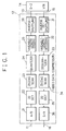
- Fig. 1 shows a state in which a first embodiment of the present invention is connected to a D-2 VTR.
- the D-2 VTR is a composite digital VTR conforming to the international standards of the national television standard committee (NTSC) or the phase alteration line (PAL) system.
- video data 11 which is high-vision data including high-definition video signals is fed to a video data compressor 12 to obtain compressed data 13.
- the data 13 is sent to a D-2 VTR 14 to be recorded on a recording medium.
- compressed data 15 outputted from the recorder 14 is fed to the compressor 12 so as to create expanded data, thereby obtaining video data 16 including analog signals.
- the video data 11 in the form of analog signals including a luminance signal and a color difference signal is delivered to an analog-to-digital (A/D) converter 21 in the compressor 12 to be transformed into digital signals.
- the signals are supplied to a two-dimensional (2D) discrete cosine transform (DCT) circuit 22.
- DCT discrete cosine transform
- the digital signals are subjected to the two-dimensional discrete cosine transform operation.
- the resultant signals are then inputted to a zigzag scan circuit 23 to undergo a zigzag scan and are thereafter inputted to a quantizing circuit 24 to be subjected to a quantization.
- the obtained signals are fed to a variable-length coding circuit 15 to produce variable-length codes.
- the codes are delivered to an inverse shuffling circuit 26 to undergo an inverse shuffling operation, thereby restoring the compressed data 13.
- the compressed data 16 supplied from the VTR 14 to an inverse de-shuffling circuit 31 is inputted to a variable-length decoding circuit 32 to undergo a decoding operation.
- the resultant data is fed to a de-quantizing circuit 33 so as to attain de-quantizaed data.
- the data is delivered to a zigzag scan circuit 34 and is then inputted to a two-dimensional inverse discrete cosine transform (IDCT) circuit 35 to be subjected to an inverse discrete cosine transform operation.
- the inversely transformed data is thereafter fed to a digital-to-analog (D/A) converter circuit 36, thereby creating video data 16 in the form of analog signals.
- D/A digital-to-analog
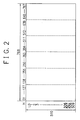
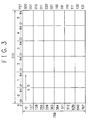
- Figs. 2 to 4 show shuffling formats predetermined for a D-2 VTR recording or transmitting apparatus.
- Fig. 3 shows a projected image the map of Fig. 2 in which letters p, q, and r take the following values.
- the transform operation is first conducted for each video block 41; thereafter, a zigzag scan, a quantization, and a variable-length coding are effected for the obtained data.
- the control operation is resultantly accomplished to allocate an appropriate number of bits to each block such that the size of each frame does not exceed the number of bits (3133440 bits) predetermined for the D-2 VTR 14.
- the video data is subjected to a serial-to-parallel conversion in the inverse shuffling circuit 26, thereby restoring the data undergone the shuffling described above.
- the order X (0 ⁇ X ⁇ 391679) of the compressed data undergone the conversion is represented by the expression (3).
- Fig. 6 shows a state in which a video data compressor in a second embodiment of the present invention is connected to a D-2 VTR. Also in the second embodiment, video data 11 in the form of high-vision data is fed to a video data compressor 51. The compressed data 52 is sent to a D-2 VTR 14 to be recorded therein. On the other hand, in a playback operation, compressed data 53 is delivered from the recorder 14 to the compressor 51 to be resultantly expanded, thereby outputting video data 54 including analog signals.
- the same components as those of Fig. 1 are assigned with the same reference numerals, and hence a redundant description thereof will be avoided.
- data outputted from a zigzag scan circuit 23 is delivered to a quantizing and coding circuit 61 to undergo a quantization and a coding operation.
- the resultant data is then inputted to a shuffling circuit 62 to be subjected to a shuffling predetermined for the compressor 51, thereby sending the obtained data to an inverse shuffling circuit 63.
- the data undergoes an inverse shuffling so as to restore the data shuffled by a shuffling operation predetermined for the recording or transmitting apparatus, thereby transmitting the resultant compressed data 52 to the recorder 14.
- the compressed data 53 is supplied from the recorder 14 to an inverse de-shuffling circuit 64 to undergo an inverse de-shuffling.
- the data is then de-shuffled by a de-shuffling circuit 65.
- the obtained data undergoes a de-quantization and a decoding operation in a de-quantizing and decoding circuit 66 and is then fed to a zigzag scan circuit 34.
- the circuit 61 is implemented by combining the quantizing circuit 24 with the variable-length coding circuit 2 of the first embodiment; whereas, the circuit 66 includes the variable-length decoding circuit 32 and the de-quantizing circuit 33 of the first embodiment.
- a frame of high-vision data including the luminance and color difference signals includes 1088 ⁇ 1536 samples.
- the data is partitioned into video blocks each including 8 lines ⁇ 8 samples such that each frame contains 26112 video blocks as described above.
- the two-dimensional discrete cosine transform is first accomplished for each video block 41.
- the data is then subjected the zigzag scan, quantization, and variable-length coding so as to allocate an appropriate number of bits to each block.
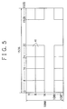
- the video data is shuffled in the 8-bit unit by the shuffling circuit 62 so as to conduct a serial-to-parallel conversion thereof, thereby achieving a shuffling operation predetermined for the compressor 51.
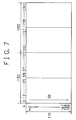
- Fig. 7 shows a data layout for the shuffling operation in which rows and arrays are respectively designated by letters m and k.
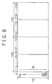
- Fig. 8 shows a map including the rows and columns represented by symbols m and n, respectively.
- the data is delivered to an inverse shuffling circuit 26 to be subjected to an inverse shuffling predetermined for the recording or transmitting apparatus.
- the high-vision data is compressed to be recorded in the D-2 VTR.
- the present invention is similarly applicable to other recording and transmitting facilities.
- video data is compressed according to a predetermined bit rate.
- data shuffled by a shuffling operation predetermined for the apparatus is restored such that dispersed data is supplied to the apparatus, thereby possibly lowering the interpolation probability on the screen.
- video data is compressed according to a predetermined bit rate.
- the attained data thus compressed is subdivided into data blocks each having a predetermined bits.
- the data blocks are subjected to a shuffling predetermined for the compressor; moreover, to concentrate errors in a recording or transmitting apparatus onto a portion of the compressed video data undergone the shuffling, the data shuffled by a shuffling operation predetermined for the apparatus is restored such that the resultant data is sent to the apparatus, thereby possibly lowering the interpolation probability on the screen and dispersing the data.
Landscapes
- Engineering & Computer Science (AREA)
- Multimedia (AREA)
- Signal Processing (AREA)
- Television Signal Processing For Recording (AREA)
- Compression Or Coding Systems Of Tv Signals (AREA)
- Two-Way Televisions, Distribution Of Moving Picture Or The Like (AREA)
Applications Claiming Priority (2)
| Application Number | Priority Date | Filing Date | Title |
|---|---|---|---|
| JP33496/93 | 1993-02-23 | ||
| JP3349693A JP2827790B2 (ja) | 1993-02-23 | 1993-02-23 | ビデオデータ圧縮装置 |
Publications (2)
| Publication Number | Publication Date |
|---|---|
| EP0613301A2 true EP0613301A2 (de) | 1994-08-31 |
| EP0613301A3 EP0613301A3 (de) | 1995-03-01 |
Family
ID=12388166
Family Applications (1)
| Application Number | Title | Priority Date | Filing Date |
|---|---|---|---|
| EP19940102582 Withdrawn EP0613301A3 (de) | 1993-02-23 | 1994-02-21 | Videodatenkompressor zur Minimierung der Fehlerfortpflanzung. |
Country Status (3)
| Country | Link |
|---|---|
| US (1) | US5510904A (de) |
| EP (1) | EP0613301A3 (de) |
| JP (1) | JP2827790B2 (de) |
Cited By (3)
| Publication number | Priority date | Publication date | Assignee | Title |
|---|---|---|---|---|
| EP0949815A3 (de) * | 1998-04-08 | 2000-05-10 | Nec Corporation | Bildverschlüsselungsmethode- und Gerät |
| EP0805599A3 (de) * | 1996-05-01 | 2003-09-17 | Oki Electric Industry Company, Limited | Videokodierer/dekodierer mit Verschlüsselungsfähigkeit |
| DE19644769B4 (de) * | 1995-10-26 | 2008-06-19 | Hyundai Electronics Industries Co., Ltd., Ichon | Vorrichtung und Verfahren zum formadaptiven Codieren von Bildsignalen |
Families Citing this family (3)
| Publication number | Priority date | Publication date | Assignee | Title |
|---|---|---|---|---|
| KR0131715B1 (ko) * | 1994-07-25 | 1998-04-16 | 조백제 | 주사방식 변환회로 |
| TW385609B (en) * | 1997-05-06 | 2000-03-21 | Winbond Electronics Corp | Method for carrying out compression data |
| JP4655171B2 (ja) * | 2000-02-14 | 2011-03-23 | ソニー株式会社 | 情報処理装置および方法 |
Family Cites Families (15)
| Publication number | Priority date | Publication date | Assignee | Title |
|---|---|---|---|---|
| JPS59147409U (ja) * | 1983-03-22 | 1984-10-02 | マメトラ農機株式会社 | 園芸用移植機における自動潅水装置 |
| JPS60116817U (ja) * | 1984-01-19 | 1985-08-07 | マメトラ農機株式会社 | 土付苗用移植機における潅水装置 |
| JPS61123280A (ja) * | 1984-11-19 | 1986-06-11 | Nec Corp | 画像デ−タ圧縮装置 |
| JPS61181286A (ja) * | 1985-02-06 | 1986-08-13 | Hitachi Ltd | 画像信号のデイジタル記録装置 |
| JPH0695751B2 (ja) * | 1986-02-27 | 1994-11-24 | ソニー株式会社 | 映像及び音声信号記録装置 |
| JPS63308474A (ja) * | 1987-06-10 | 1988-12-15 | Matsushita Electric Ind Co Ltd | 画像デ−タ圧縮装置 |
| JPH01167818U (de) * | 1988-05-13 | 1989-11-27 | ||
| EP0467717B1 (de) * | 1990-07-20 | 1998-01-14 | Matsushita Electric Industrial Co., Ltd. | Datenmischendes Gerät |
| EP0471118B1 (de) * | 1990-08-13 | 1995-12-20 | Matsushita Electric Industrial Co., Ltd. | Digitale Videosignalaufnahme- und -wiedergabevorrichtung |
| TW223690B (de) * | 1991-02-13 | 1994-05-11 | Ampex | |
| EP0509594B1 (de) * | 1991-04-18 | 1997-10-22 | Koninklijke Philips Electronics N.V. | System und Verfahren zur Verbesserung der Suchbetriebsart bei einem Video Recorder |
| JP3348288B2 (ja) * | 1991-07-19 | 2002-11-20 | ソニー株式会社 | ディジタルビデオ信号の記録方法および装置 |
| JP3141896B2 (ja) * | 1991-08-09 | 2001-03-07 | ソニー株式会社 | ディジタルビデオ信号の記録装置 |
| JP2706398B2 (ja) * | 1992-02-14 | 1998-01-28 | シャープ株式会社 | 映像信号のディジタル記録装置及び再生装置 |
| JP2708312B2 (ja) * | 1992-03-05 | 1998-02-04 | 松下電器産業株式会社 | 記録装置及び再生装置 |
-
1993
- 1993-02-23 JP JP3349693A patent/JP2827790B2/ja not_active Expired - Fee Related
-
1994
- 1994-02-21 EP EP19940102582 patent/EP0613301A3/de not_active Withdrawn
- 1994-02-23 US US08/200,754 patent/US5510904A/en not_active Expired - Lifetime
Cited By (4)
| Publication number | Priority date | Publication date | Assignee | Title |
|---|---|---|---|---|
| DE19644769B4 (de) * | 1995-10-26 | 2008-06-19 | Hyundai Electronics Industries Co., Ltd., Ichon | Vorrichtung und Verfahren zum formadaptiven Codieren von Bildsignalen |
| EP0805599A3 (de) * | 1996-05-01 | 2003-09-17 | Oki Electric Industry Company, Limited | Videokodierer/dekodierer mit Verschlüsselungsfähigkeit |
| EP0949815A3 (de) * | 1998-04-08 | 2000-05-10 | Nec Corporation | Bildverschlüsselungsmethode- und Gerät |
| US6584200B1 (en) | 1998-04-08 | 2003-06-24 | Nec Corporation | Image scrambling method and apparatus therefor |
Also Published As
| Publication number | Publication date |
|---|---|
| JP2827790B2 (ja) | 1998-11-25 |
| EP0613301A3 (de) | 1995-03-01 |
| US5510904A (en) | 1996-04-23 |
| JPH06253260A (ja) | 1994-09-09 |
Similar Documents
| Publication | Publication Date | Title |
|---|---|---|
| EP0367264B1 (de) | Digitaler Videobandrecorder, geeignet zur Bildwiedergabe mit hoher Geschwindigkeit | |
| EP0629085B1 (de) | Hochauflösender Fernsehempfänger mit Merkmalen die besondere Wiedergabebetriebsarten in einem digitalen Videokassettenrekorder vereinfachen | |
| JP3134424B2 (ja) | 可変長符号化方法及び装置 | |
| EP0527611B1 (de) | Vorrichtung zum Aufzeichnen eines digitalen Videosignals | |
| US5550640A (en) | Digital video signal recording and reproducing apparatus and method for setting a number of compression blocks according to different operational modes | |
| EP0613297B1 (de) | Digitaler Videorecorder für hochauflösende Fernsehsignale mit Betriebsarten für spezielle Wiedergabe | |
| EP0680209B1 (de) | Fernsehbildkodier- und Aufnahmevorrichtung und Fernsehbildkodier-, Aufnahme- und Wiedergabevorrichtung | |
| EP0771109A2 (de) | Aufnahmevorrichtung für digitale Videosignale | |
| US5349384A (en) | Apparatus and methods for transmitting compressed digital image signals | |
| EP0575997B1 (de) | Vorrichtung zum Verarbeiten des Signals eines digitalen Videocassettenrecorders | |
| EP1377071A1 (de) | Bildverarbeitungseinrichtung, bildverarbeitungsverfahren, bildverarbeitungsprogramm und aufzeichnungsmedium | |
| US4982270A (en) | Video data transmitting system | |
| EP0602817B1 (de) | Vorrichtung zum Verarbeiten eines digitalen Videosignals | |
| US5510904A (en) | Video data compressor minimizing propagation of error | |
| EP0920212B1 (de) | Vorrichtung zur Videokodierung | |
| EP0666692B1 (de) | Gerät zur Aufzeichnung und Wiedergabe von komprimierten oder nicht-komprimierten digitalen Videodaten mit Kompressionsadapter | |
| US6219157B1 (en) | Image coding apparatus | |
| US5585855A (en) | Digital video signal coding circuit, digital signal decoding circuit | |
| EP0523708B1 (de) | Verfahren und Vorrichtung zum Aufzeichnen von digitalen Videosignalen | |
| JP3153950B2 (ja) | 画像圧縮符号化装置及び画像圧縮復号化装置 | |
| US6263107B1 (en) | Image processing apparatus | |
| EP0772366A2 (de) | Digitales Aufzeichnungs-/Wiedergabegerät | |
| JP3216277B2 (ja) | 高能率符号化装置および復号化装置 | |
| JP3291785B2 (ja) | ブロック変換符号化データの伝送装置 | |
| JPH09200694A (ja) | 画像符号化記録再生装置 |
Legal Events
| Date | Code | Title | Description |
|---|---|---|---|
| PUAI | Public reference made under article 153(3) epc to a published international application that has entered the european phase |
Free format text: ORIGINAL CODE: 0009012 |
|
| AK | Designated contracting states |
Kind code of ref document: A2 Designated state(s): DE FR GB |
|
| PUAL | Search report despatched |
Free format text: ORIGINAL CODE: 0009013 |
|
| AK | Designated contracting states |
Kind code of ref document: A3 Designated state(s): DE FR GB |
|
| 17P | Request for examination filed |
Effective date: 19950116 |
|
| 17Q | First examination report despatched |
Effective date: 20050609 |
|
| STAA | Information on the status of an ep patent application or granted ep patent |
Free format text: STATUS: THE APPLICATION IS DEEMED TO BE WITHDRAWN |
|
| 18D | Application deemed to be withdrawn |
Effective date: 20051020 |