EP0613426B1 - Kupplungssteuerungssystem - Google Patents
Kupplungssteuerungssystem Download PDFInfo
- Publication number
- EP0613426B1 EP0613426B1 EP92923874A EP92923874A EP0613426B1 EP 0613426 B1 EP0613426 B1 EP 0613426B1 EP 92923874 A EP92923874 A EP 92923874A EP 92923874 A EP92923874 A EP 92923874A EP 0613426 B1 EP0613426 B1 EP 0613426B1
- Authority
- EP
- European Patent Office
- Prior art keywords
- clutch
- signal
- speed
- vehicle
- engine
- Prior art date
- Legal status (The legal status is an assumption and is not a legal conclusion. Google has not performed a legal analysis and makes no representation as to the accuracy of the status listed.)
- Expired - Lifetime
Links
- 230000007935 neutral effect Effects 0.000 claims description 5
- 238000005096 rolling process Methods 0.000 description 3
- 230000000994 depressogenic effect Effects 0.000 description 2
- 238000010586 diagram Methods 0.000 description 2
- 230000001960 triggered effect Effects 0.000 description 2
- 230000005540 biological transmission Effects 0.000 description 1
- 230000001419 dependent effect Effects 0.000 description 1
- 239000000446 fuel Substances 0.000 description 1
- 238000004519 manufacturing process Methods 0.000 description 1
- 230000000284 resting effect Effects 0.000 description 1
- 238000007493 shaping process Methods 0.000 description 1
Images

Classifications
-
- F—MECHANICAL ENGINEERING; LIGHTING; HEATING; WEAPONS; BLASTING
- F16—ENGINEERING ELEMENTS AND UNITS; GENERAL MEASURES FOR PRODUCING AND MAINTAINING EFFECTIVE FUNCTIONING OF MACHINES OR INSTALLATIONS; THERMAL INSULATION IN GENERAL
- F16D—COUPLINGS FOR TRANSMITTING ROTATION; CLUTCHES; BRAKES
- F16D48/00—External control of clutches
- F16D48/06—Control by electric or electronic means, e.g. of fluid pressure
- F16D48/066—Control of fluid pressure, e.g. using an accumulator
-
- F—MECHANICAL ENGINEERING; LIGHTING; HEATING; WEAPONS; BLASTING
- F16—ENGINEERING ELEMENTS AND UNITS; GENERAL MEASURES FOR PRODUCING AND MAINTAINING EFFECTIVE FUNCTIONING OF MACHINES OR INSTALLATIONS; THERMAL INSULATION IN GENERAL
- F16D—COUPLINGS FOR TRANSMITTING ROTATION; CLUTCHES; BRAKES
- F16D48/00—External control of clutches
- F16D48/06—Control by electric or electronic means, e.g. of fluid pressure
-
- B—PERFORMING OPERATIONS; TRANSPORTING
- B60—VEHICLES IN GENERAL
- B60W—CONJOINT CONTROL OF VEHICLE SUB-UNITS OF DIFFERENT TYPE OR DIFFERENT FUNCTION; CONTROL SYSTEMS SPECIALLY ADAPTED FOR HYBRID VEHICLES; ROAD VEHICLE DRIVE CONTROL SYSTEMS FOR PURPOSES NOT RELATED TO THE CONTROL OF A PARTICULAR SUB-UNIT
- B60W50/00—Details of control systems for road vehicle drive control not related to the control of a particular sub-unit, e.g. process diagnostic or vehicle driver interfaces
- B60W2050/0001—Details of the control system
- B60W2050/0002—Automatic control, details of type of controller or control system architecture
- B60W2050/0008—Feedback, closed loop systems or details of feedback error signal
- B60W2050/001—Proportional integral [PI] controller
-
- B—PERFORMING OPERATIONS; TRANSPORTING
- B60—VEHICLES IN GENERAL
- B60W—CONJOINT CONTROL OF VEHICLE SUB-UNITS OF DIFFERENT TYPE OR DIFFERENT FUNCTION; CONTROL SYSTEMS SPECIALLY ADAPTED FOR HYBRID VEHICLES; ROAD VEHICLE DRIVE CONTROL SYSTEMS FOR PURPOSES NOT RELATED TO THE CONTROL OF A PARTICULAR SUB-UNIT
- B60W50/00—Details of control systems for road vehicle drive control not related to the control of a particular sub-unit, e.g. process diagnostic or vehicle driver interfaces
- B60W2050/0001—Details of the control system
- B60W2050/0043—Signal treatments, identification of variables or parameters, parameter estimation or state estimation
- B60W2050/0052—Filtering, filters
-
- B—PERFORMING OPERATIONS; TRANSPORTING
- B60—VEHICLES IN GENERAL
- B60W—CONJOINT CONTROL OF VEHICLE SUB-UNITS OF DIFFERENT TYPE OR DIFFERENT FUNCTION; CONTROL SYSTEMS SPECIALLY ADAPTED FOR HYBRID VEHICLES; ROAD VEHICLE DRIVE CONTROL SYSTEMS FOR PURPOSES NOT RELATED TO THE CONTROL OF A PARTICULAR SUB-UNIT
- B60W2510/00—Input parameters relating to a particular sub-units
- B60W2510/06—Combustion engines, Gas turbines
- B60W2510/0638—Engine speed
-
- B—PERFORMING OPERATIONS; TRANSPORTING
- B60—VEHICLES IN GENERAL
- B60W—CONJOINT CONTROL OF VEHICLE SUB-UNITS OF DIFFERENT TYPE OR DIFFERENT FUNCTION; CONTROL SYSTEMS SPECIALLY ADAPTED FOR HYBRID VEHICLES; ROAD VEHICLE DRIVE CONTROL SYSTEMS FOR PURPOSES NOT RELATED TO THE CONTROL OF A PARTICULAR SUB-UNIT
- B60W2710/00—Output or target parameters relating to a particular sub-units
- B60W2710/02—Clutches
- B60W2710/021—Clutch engagement state
- B60W2710/022—Clutch actuator position
-
- F—MECHANICAL ENGINEERING; LIGHTING; HEATING; WEAPONS; BLASTING
- F16—ENGINEERING ELEMENTS AND UNITS; GENERAL MEASURES FOR PRODUCING AND MAINTAINING EFFECTIVE FUNCTIONING OF MACHINES OR INSTALLATIONS; THERMAL INSULATION IN GENERAL
- F16D—COUPLINGS FOR TRANSMITTING ROTATION; CLUTCHES; BRAKES
- F16D2500/00—External control of clutches by electric or electronic means
- F16D2500/10—System to be controlled
- F16D2500/104—Clutch
- F16D2500/10443—Clutch type
- F16D2500/1045—Friction clutch
-
- F—MECHANICAL ENGINEERING; LIGHTING; HEATING; WEAPONS; BLASTING
- F16—ENGINEERING ELEMENTS AND UNITS; GENERAL MEASURES FOR PRODUCING AND MAINTAINING EFFECTIVE FUNCTIONING OF MACHINES OR INSTALLATIONS; THERMAL INSULATION IN GENERAL
- F16D—COUPLINGS FOR TRANSMITTING ROTATION; CLUTCHES; BRAKES
- F16D2500/00—External control of clutches by electric or electronic means
- F16D2500/30—Signal inputs
- F16D2500/306—Signal inputs from the engine
- F16D2500/3067—Speed of the engine
-
- F—MECHANICAL ENGINEERING; LIGHTING; HEATING; WEAPONS; BLASTING
- F16—ENGINEERING ELEMENTS AND UNITS; GENERAL MEASURES FOR PRODUCING AND MAINTAINING EFFECTIVE FUNCTIONING OF MACHINES OR INSTALLATIONS; THERMAL INSULATION IN GENERAL
- F16D—COUPLINGS FOR TRANSMITTING ROTATION; CLUTCHES; BRAKES
- F16D2500/00—External control of clutches by electric or electronic means
- F16D2500/30—Signal inputs
- F16D2500/308—Signal inputs from the transmission
- F16D2500/30806—Engaged transmission ratio
-
- F—MECHANICAL ENGINEERING; LIGHTING; HEATING; WEAPONS; BLASTING
- F16—ENGINEERING ELEMENTS AND UNITS; GENERAL MEASURES FOR PRODUCING AND MAINTAINING EFFECTIVE FUNCTIONING OF MACHINES OR INSTALLATIONS; THERMAL INSULATION IN GENERAL
- F16D—COUPLINGS FOR TRANSMITTING ROTATION; CLUTCHES; BRAKES
- F16D2500/00—External control of clutches by electric or electronic means
- F16D2500/30—Signal inputs
- F16D2500/31—Signal inputs from the vehicle
- F16D2500/3108—Vehicle speed
-
- F—MECHANICAL ENGINEERING; LIGHTING; HEATING; WEAPONS; BLASTING
- F16—ENGINEERING ELEMENTS AND UNITS; GENERAL MEASURES FOR PRODUCING AND MAINTAINING EFFECTIVE FUNCTIONING OF MACHINES OR INSTALLATIONS; THERMAL INSULATION IN GENERAL
- F16D—COUPLINGS FOR TRANSMITTING ROTATION; CLUTCHES; BRAKES
- F16D2500/00—External control of clutches by electric or electronic means
- F16D2500/30—Signal inputs
- F16D2500/314—Signal inputs from the user
- F16D2500/3146—Signal inputs from the user input from levers
- F16D2500/31466—Gear lever
-
- F—MECHANICAL ENGINEERING; LIGHTING; HEATING; WEAPONS; BLASTING
- F16—ENGINEERING ELEMENTS AND UNITS; GENERAL MEASURES FOR PRODUCING AND MAINTAINING EFFECTIVE FUNCTIONING OF MACHINES OR INSTALLATIONS; THERMAL INSULATION IN GENERAL
- F16D—COUPLINGS FOR TRANSMITTING ROTATION; CLUTCHES; BRAKES
- F16D2500/00—External control of clutches by electric or electronic means
- F16D2500/50—Problem to be solved by the control system
- F16D2500/502—Relating the clutch
- F16D2500/50224—Drive-off
-
- F—MECHANICAL ENGINEERING; LIGHTING; HEATING; WEAPONS; BLASTING
- F16—ENGINEERING ELEMENTS AND UNITS; GENERAL MEASURES FOR PRODUCING AND MAINTAINING EFFECTIVE FUNCTIONING OF MACHINES OR INSTALLATIONS; THERMAL INSULATION IN GENERAL
- F16D—COUPLINGS FOR TRANSMITTING ROTATION; CLUTCHES; BRAKES
- F16D2500/00—External control of clutches by electric or electronic means
- F16D2500/50—Problem to be solved by the control system
- F16D2500/508—Relating driving conditions
- F16D2500/50825—Hill climbing or descending
-
- F—MECHANICAL ENGINEERING; LIGHTING; HEATING; WEAPONS; BLASTING
- F16—ENGINEERING ELEMENTS AND UNITS; GENERAL MEASURES FOR PRODUCING AND MAINTAINING EFFECTIVE FUNCTIONING OF MACHINES OR INSTALLATIONS; THERMAL INSULATION IN GENERAL
- F16D—COUPLINGS FOR TRANSMITTING ROTATION; CLUTCHES; BRAKES
- F16D2500/00—External control of clutches by electric or electronic means
- F16D2500/70—Details about the implementation of the control system
- F16D2500/706—Strategy of control
- F16D2500/70668—Signal filtering
Definitions
- the present invention relates to a clutch control system for a vehicle.
- Our patent GB 2 088 007 describes a clutch control system in which the clutch is progressively engaged as the torque demand issued by the driver increases to temporarily limit the engine speed to a set value.
- Our patent US-A-4561530 describes a clutch control system in which a gain control is provided to adjust the gain applied to a clutch position signal before its comparison with a clutch command signal. Both these systems provide a smooth take up from rest but suffer from the disadvantage that if the vehicle while in gear should roll down a hill gathering speed while the engine is still idle, the clutch will not engage to provide a degree of braking, nor can the driver make it engage without speeding up the engine using the speed control means, an action that would appear to him totally unnatural in a circumstance when he wanted to cause the vehicle to be restrained. Furthermore, if the engine cannot be started due to failure or partial failure of the self-starting system, the engine cannot be started by any of the commonly accepted emergency starting means such as push starting or tow-starting.
- the present invention provides a clutch control system for a vehicle having a clutch, a gearbox and an engine, the system comprising a vehicle speed sensor for generating a vehicle speed signal variable with the speed of the vehicle, and a clutch engagement signal generator that produces a signal utilised for controlling a clutch actuation means that operates the clutch engagement, the system being characterised by the inclusion of a filter means that receives the engagement signal and the engine speed to generate a clutch actuation means for engagement of the clutch in the event that either the vehicle speed signal and/or the engagement signal exceeds a predetermined minimum value.
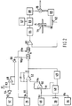
- a vehicle comprises an engine 10 and a gearbox 12 coupled through a clutch 14, via a clutch driven plate 13 and a gearbox input shaft 15.
- Fuel is supplied to the engine by a throttle 16 which includes a throttle valve 18 operated by accelerator pedal 19.
- the clutch 14 is actuated by a release fork 20 which is operated by a slave cylinder 22.
- the gearbox is operated by a gear lever 24.
- An engine speed signal generator comprises an engine speed sensor 26 which includes a transducer.
- the state of the throttle valve 18 is monitored by a throttle valve position sensor 30.
- the state of the gearbox 12 is monitored by a gear position sensor 32.
- the position of the slave cylinder 22 is monitored by an actuation sensor 34.
- the speed of the gearbox output shaft 15 is monitored by a vehicle speed sensor 42. Since the speed of the vehicle depends on the driven plate speed and the gear engaged, the speed sensor can be used to calculate the driven plate speed. Signals from the sensors are transmitted to a control unit 36 which controls the actuation of the clutch via a hydraulic control 38.
- the system also includes a choke position sensor 44 and a reference signal generator 46.
- the throttle position sensor 30 produces a throttle signal Vt which is fed to an inverting input of a difference amplifier 50 via a limiter 48.
- the limiter 48 receives an input from a switching circuit 49.
- a reference signal Vr from the reference signal generator 46 is combined with a choke signal Vc from the choke position sensor 44 and input to the difference amplifier 50.
- the output Vs of the difference amplifier 50 being the sum of Vt, Vr and Vc, forms a modified reference signal which is fed to the input of a comparator 52.
- the engine speed sensor 26 produces an engine speed signal Ve which is fed via the resistor R1 to the comparator 52.
- the speed sensor 42 produces a signal V2 which is fed to a circuit containing diodes 54 and 56 and a high impedance buffer 58.
- the diode 54 has its output connected via a resistance R3 to a supply of constant voltage V1 which in this case is 5v.
- the input of the diode 54 is connected via the high impedance buffer 58 to the input of the diode 56, the output Vdp of which is connected to a filter 71.
- the output Vdp from this circuit forms a vehicle speed signal.
- the comparator 52 produces a clutch engagement signal E which equals the difference between the modified reference signal Vs and the engine speed signal Ve.
- the error signal E is also fed into an input of the filter 71 which operates to allow either signal Vdp or E to pass through should either of said signals exceed a predetermined minimum value.
- the clutch actuator signal A from the filter 71 passes to a anti-stall limiter 72.
- the limiter 72 receives the engine speed signal Ve and is an enable/disable switch that operates to determine the maximum degree of engagement of the clutch above an engine speed 600 rpm and does not switch off until the engine speed falls to 0 rpm.
- the limiter 72 is connected to a clutch position control comparator 60 the other input of which receives a signal from a clutch position sensor 62.
- the output from the comparator 60 is fed via a phase gain shaping network 64 to a mark to space ratio modulator 66 which also has as input a signal from an oscillator 67.
- the output signal from the mark to space ratio modulator 66 is fed via an output 68 to a valve 70, which controls the position of the clutch 14 via a hydraulic control 69.
- the output from comparator 60 may be fed into a current feed back amplifier which drives the control valve 70.
- the speed signal Vdp will increase with vehicle speed and the engagement signal E will be positive.
- Vdp exceeds a predetermined value it will cause the clutch actuator control systems 60,62,64,66,67,68 etc. to operate independently of the engagement signal E to engage the clutch causing the engine speed signal Ve to increase.
- Ve becomes equal to Vs the engagement signal E overrides the signal to control clutch engagement.
- the clutch will be prevented from engaging unless the vehicle transmission is firstly in neutral.
- the system is sensitive to the selection of neutral or a given gear through the sensor 32 which also indicates if the lever 24 is subsequently used to move from neutral to select a gear which the clutch will engage. This prevents "bump starting” if the driver is not in the driving seat.
- the limiter 72 prevents engine stall by limiting the clutch engagement to a maximum torque determined by the engine speed signal Ve.
- the limiter is only triggered to operate when the engine speed exceeds 600 rpm to allow the tow start to operate.
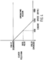
- the clutch is operated to be fully disengaged at 0 rpm and fully engaged at 1200 rpm. In normal operation the clutch will begin to engage above 600 rpm. Should the engine speed fall as the clutch is engaged the reduction in the engine speed signal will cause the clutch to disengage. This is shown in Fig 4. To engage the clutch the engine speed must be increased allowing a higher than normal torque to pass through the clutch.
- Vdp will be proportional to the speed at which the vehicle is rolling.
- the driven plate speed can be computed if required by a constant of proportional which will depend on which gear is engaged.
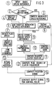
- a microprocessor the processing of signals from the sensors and the production of a signal for actuation of the clutch is performed by a microprocessor.
- a basic speed reference is retrieved, the value of the speed reference having been set when the microprocessor was produced.
- the idle speed is examined. The idle speed would have a set value which could be set higher, eg for a cold start. If the idle speed is set high, the microprocessor proceeds to step 3 to compute an increased speed reference. If the idle speed is at its normal set value step 3 is bypassed and the speed reference is unaltered.
- a throttle setting signal is generated, and at step 5 the speed reference is increased by an increment dependent on the throttle setting signal.
- an engine speed signal is generated and this is compared with the reference signal at step 9 to produce a speed error signal representing the difference between the engine speed and reference speed.
- the error signal and the integral with respect to time of the error signal are generated at step 10 and combined to determine at step 11 a required clutch position. When the error reaches zero or is negative the error signal and its integral are used in combination.
- An actual clutch position signal is generated at step 12 and composed with the required clutch position signal at step 13 to produce a position error, which generates at step 14 an output signal for the control valve 70 of the clutch hydraulic actuation .
- a vehicle speed signal is generated and if the car is sequentially placed in neutral, then in gear, and is moving at more than a predetermined speed a vehicle rolling signal is generated which is fed into the step 11. This will cause the clutch to engage independently of the error signal, and allow the vehicle to be tow-started.
- the microprocessor software operates to cause a full clutch engagement above a predetermined road speed and/or a predetermined engine speed. Below the predetermined engine speed assuming a stationary vehicle the engagement of the clutch is proportional to the engine speed signal.
- the microprocessor may also be altered so as to operate in an equivalent manner to the analogue circuit described in our earlier patent no. 2079 088, which provides an improved hill start capacity.
- the part of the microprocessor with forms a comparator means for performing steps 6 to 9 could be arranged differently and the order of the comparisons of engine speed, driven plate speed and reference could be altered.
- the engine speed signal and driven plate speed signal could each be compared with the reference signal to produce two error signals, the greater of which could be used to compute a required clutch position.
- the clutch engagement signal from the step 11 is passed into a step 12 to compute to maximise engagement of the clutch set by the engine speed signal. This step is only triggered when the engine speed exceeds 600 rpm on start up.
- Step 14 compares the actual clutch position from step 13 with the maximum engagement clutch position from step 12 and generates an output at 15 which causes the clutch to engage to the desired position, if this is within the limit set by the engine speed value. If not the clutch will only engage up to a maximum torque set by the engine speed value.
Landscapes
- Engineering & Computer Science (AREA)
- General Engineering & Computer Science (AREA)
- Physics & Mathematics (AREA)
- Fluid Mechanics (AREA)
- Mechanical Engineering (AREA)
- Hydraulic Clutches, Magnetic Clutches, Fluid Clutches, And Fluid Joints (AREA)
- Control Of Driving Devices And Active Controlling Of Vehicle (AREA)
Claims (9)
- Steuerungssystem einer Reibungskupplung für ein Fahrzeug mit einer Kupplung (14), einem Mehrganggetriebe (12) und einem Motor (10), wobei das System einen Meßfühler (42) für die Fahrzeuggeschwindigkeit zur Erzeugung eines Fahrzeuggeschwindigkeitsignals (Vdp), das mit der Fahrzeuggeschwindigkeit veränderlich ist, und einen Generator (46, 50, 52) für ein Kupplungseingriffsignal aufweist, der ein Eingriffssignal (E) erzeugt, das zur Steuerung einer Kupplungsbetätigungseinrichtung (69) verwendet wird, die die Kupplung einkuppelt, gekennzeichnet durch eine Filtereinrichtung (71), die das Eingriffssignal (E) und das Fahrzeuggeschwindigkeitssignal (Vdp) empfängt, um ein Kupplungsbetätigungssignal (A) für die Betätigung der Kupplungsbetätigungseinrichtung (69) zum Eingriff der Kupplung in dem Fall zu erzeugen, daß entweder das Fahrzeuggeschwindigkeitssignal (Vdp) und/oder das Eingriffssignal (E) einen bestimmten Minimalwert überschreitet.
- Steuerungssystem nach Anspruch 1, dadurch gekennzeichnet, daß das Kupplungsbetätigungssignal (A) in einen Begrenzer (72) geführt wird, der auch ein Fahrzeugmotordrehzahlsignal (Ve) empfängt, wobei der Begrenzer es durch die Motordrehzahl, die einen bestimmten Wert überschreitet, ermöglicht, daß die Einkupplung der Kupplung (14) bis zu einem zweiten bestimmten Wert der Motordrehzahl proportional zu der Motordrehzahl ist, wo die Kupplung vollständig eingekuppelt sein kann.
- Steuerungssystem nach Anspruch 1 oder Anspruch 2, gekennzeichnet durch einen Gangstellungsmeßfühler (32), der verwendet wird, um die Kupplungsbetätigungseinrichtung (69) zu steuern, so daß, wenn der Motor (10) nicht läuft, die Kupplung (14) nur einkuppelbar ist, wenn das Fahrzeuggeschwindigkeitssignal (Vdp) einen Minimalwert überschreitet, das Fahrzeug im Leerlauf ist, und dann daraufhin bei dem Fahrzeug ein Gang eingelegt wird.
- Steuerungssystem nach einem der Ansprüche 1 bis 3, dadurch gekennzeichnet, daß, wenn der Motor (10) läuft, und die Fahrzeuggeschwindigkeit (Vdp) den bestimmten Wert überschreitet, die Kupplung (14) auf eine Stärke der Einkupplung gesetzt wird, um die Motordrehzahl auf einen bestimmten Wert zu regeln.
- Steuerungssystem nach einem der Ansprüche 1 bis 4, dadurch gekennzeichnet, daß, wenn der Motor (10) nicht läuft, und die Fahrzeuggeschwindigkeit (Vdp) unter einen weiteren bestimmten Wert fällt, die Kupplung (14) ausgekuppelt wird.
- Steuerungssystem nach einem der vorhergehenden Ansprüche, dadurch gekennzeichnet, daß der Meßfühler (42) für die Fahrzeuggeschwindigkeit eine Einrichtung zum Messen der Drehzahl (Vdp) der Kupplungsscheibe der Kupplung (14) aufweist.
- Steuerungssystem nach einem der Ansprüche 1 bis 5, dadurch gekennzeichnet, daß der Meßfühler (42) der Fahrzeuggeschwindigkeit einer Einrichtung zum Messen der Drehgeschwindigkeit eines Ausgangs von dem Getriebe (12) aufweist.
- Steuerungssystem nach einem der Ansprüche 6 oder 7, dadurch gekennzeichnet, daß der Meßfühler der Fahrzeuggeschwindigkeit des weiteren eine Einrichtung zum Verändern der gemessenen Drehzahl der Kupplungsscheibe oder des Getriebeausgangs gemäß dem im Getriebe eingelegten Gang aufweist.
- Steuerungssystem nach Anspruch 2, dadurch gekennzeichnet, daß die Filtereinrichtung, der Begrenzer und weitere Kontrollfunktionen durch einen Mikroprozessor ausgeführt werden.
Applications Claiming Priority (3)
| Application Number | Priority Date | Filing Date | Title |
|---|---|---|---|
| GB919125161A GB9125161D0 (en) | 1991-11-27 | 1991-11-27 | A clutch control system |
| GB9125161 | 1991-11-27 | ||
| PCT/GB1992/002138 WO1993010994A1 (en) | 1991-11-27 | 1992-11-19 | A clutch control system |
Publications (2)
| Publication Number | Publication Date |
|---|---|
| EP0613426A1 EP0613426A1 (de) | 1994-09-07 |
| EP0613426B1 true EP0613426B1 (de) | 1997-01-02 |
Family
ID=10705291
Family Applications (1)
| Application Number | Title | Priority Date | Filing Date |
|---|---|---|---|
| EP92923874A Expired - Lifetime EP0613426B1 (de) | 1991-11-27 | 1992-11-19 | Kupplungssteuerungssystem |
Country Status (7)
| Country | Link |
|---|---|
| US (1) | US5489012A (de) |
| EP (1) | EP0613426B1 (de) |
| JP (1) | JP3397787B2 (de) |
| KR (1) | KR100252771B1 (de) |
| DE (1) | DE69216429T2 (de) |
| GB (1) | GB9125161D0 (de) |
| WO (1) | WO1993010994A1 (de) |
Families Citing this family (14)
| Publication number | Priority date | Publication date | Assignee | Title |
|---|---|---|---|---|
| GB9402730D0 (en) * | 1994-02-12 | 1994-04-06 | Automotive Products Plc | Clutch control system |
| US5609550A (en) * | 1995-04-17 | 1997-03-11 | Chrysler Corporation | Method for diagnosing a torque converter's lock-up mechanism |
| JPH08318762A (ja) * | 1995-05-25 | 1996-12-03 | Mitsubishi Electric Corp | 自動変速機付車両のクラッチ制御方法及び装置 |
| US5993350A (en) * | 1997-12-01 | 1999-11-30 | Lawrie; Robert E. | Automated manual transmission clutch controller |
| US5943918A (en) * | 1997-12-01 | 1999-08-31 | Chrysler Corporation | Powertrain system for a hybrid electric vehicle |
| US6186925B1 (en) | 1998-11-13 | 2001-02-13 | Cummins Engine Company, Inc. | System for protecting drive train components from excessive engine inertial forces |
| DE19920803C2 (de) * | 1999-05-06 | 2003-05-08 | Zf Sachs Ag | Anordnung zur Betätigung einer Reibungskupplung |
| US6557687B1 (en) * | 1999-07-20 | 2003-05-06 | Power Transmission Technology, Inc. | Clutch assembly and diagnostic system |
| JP3572393B2 (ja) * | 1999-09-30 | 2004-09-29 | 日産自動車株式会社 | トロイダル型無段変速機のスリップ防止装置 |
| US6375596B1 (en) * | 2000-09-12 | 2002-04-23 | Eaton Corporation | Control to determine input shaft direction of rotation |
| WO2002025131A1 (de) * | 2000-09-18 | 2002-03-28 | Siemens Aktiengesellschaft | Verfahren zum steuern einer automatischen kraftfahrzeugkupplung |
| US6641505B2 (en) * | 2002-01-30 | 2003-11-04 | Zf Meritor, Llc | Method of preventing engine stall using automated clutch control |
| DE102007030490A1 (de) * | 2007-06-30 | 2009-01-02 | Zf Friedrichshafen Ag | Verfahren zur Betätigung einer Kupplung eines Antriebsstrangs |
| CN102996680B (zh) * | 2012-11-29 | 2015-12-02 | 浙江吉利汽车研究院有限公司杭州分公司 | 一种辅助离合器系统 |
Family Cites Families (10)
| Publication number | Priority date | Publication date | Assignee | Title |
|---|---|---|---|---|
| DE2657524C3 (de) * | 1976-12-18 | 1981-07-23 | Voith Getriebe Kg, 7920 Heidenheim | Steuervorrichtung für eine durch einen hydraulischen Stellzylinder ausrückbare Hauptkupplung für Kraftfahrzeuge |
| SU1195896A3 (ru) * | 1980-11-04 | 1985-11-30 | Automotive Prod Co Ltd | "элektpohhaя cиctema упpabлehия фpиkциohhoй mуфtoй cцeплehия tpahcпopthoгo cpeдctba" |
| AU552105B2 (en) * | 1981-02-24 | 1986-05-22 | Automotive Products Ltd. | Clutch control system |
| GB2096253B (en) * | 1981-04-08 | 1985-04-03 | Automotive Prod Co Ltd | Controlling vehicle clutch during gear ratio changes |
| AU1725283A (en) * | 1982-08-11 | 1984-02-16 | Automotive Products Plc | Clutch control system |
| JPH0729569B2 (ja) * | 1983-06-29 | 1995-04-05 | いすゞ自動車株式会社 | 自動クラッチ制御装置 |
| FR2613987A1 (fr) * | 1987-04-16 | 1988-10-21 | Tallec Philippe | Dispositif de commande automatique pour un embrayage a friction, applica |
| DE3737899A1 (de) * | 1987-11-07 | 1989-08-03 | Sachs Systemtechnik Gmbh | Vorrichtung zur automatischen betaetigung einer reibungskupplung |
| JP2706154B2 (ja) * | 1989-10-05 | 1998-01-28 | スズキ株式会社 | 自動発進クラッチの制御装置 |
| GB2250075B (en) * | 1990-11-02 | 1994-09-07 | Automotive Products Plc | A clutch control system |
-
1991
- 1991-11-27 GB GB919125161A patent/GB9125161D0/en active Pending
-
1992
- 1992-11-19 KR KR1019940701715A patent/KR100252771B1/ko not_active Expired - Fee Related
- 1992-11-19 EP EP92923874A patent/EP0613426B1/de not_active Expired - Lifetime
- 1992-11-19 JP JP50991893A patent/JP3397787B2/ja not_active Expired - Fee Related
- 1992-11-19 WO PCT/GB1992/002138 patent/WO1993010994A1/en not_active Ceased
- 1992-11-19 DE DE69216429T patent/DE69216429T2/de not_active Expired - Lifetime
- 1992-11-19 US US08/244,080 patent/US5489012A/en not_active Expired - Lifetime
Also Published As
| Publication number | Publication date |
|---|---|
| US5489012A (en) | 1996-02-06 |
| JPH07501385A (ja) | 1995-02-09 |
| DE69216429D1 (de) | 1997-02-13 |
| EP0613426A1 (de) | 1994-09-07 |
| KR100252771B1 (ko) | 2000-04-15 |
| GB9125161D0 (en) | 1992-01-29 |
| JP3397787B2 (ja) | 2003-04-21 |
| WO1993010994A1 (en) | 1993-06-10 |
| DE69216429T2 (de) | 1997-07-17 |
Similar Documents
| Publication | Publication Date | Title |
|---|---|---|
| KR100367482B1 (ko) | 클러치제어시스템 | |
| EP0328362B1 (de) | Steuerung für den Fahrzeugstartvorgang | |
| EP0328299B1 (de) | Steuerung des Anlaufens vom Stillstand bei einem automatisch-mechanischen Getriebesystem | |
| EP0613426B1 (de) | Kupplungssteuerungssystem | |
| US4714144A (en) | Method for controlling AMT system start from stop operation | |
| US5630773A (en) | Method and apparatus for slip mode control of automatic clutch | |
| US4971183A (en) | Device for the automatic actuation of a friction clutch | |
| EP0043660B1 (de) | Kupplungssteueranlage | |
| US6358186B1 (en) | Apparatus and method for controlling a torque transmitting system | |
| JPH03136929A (ja) | 車両走行制御装置 | |
| EP0735957B1 (de) | Kupplungs-steuerungssystem | |
| JPH06504606A (ja) | クラッチ制御システム | |
| US4633985A (en) | Control of the supply pressure of a hydraulic actuator | |
| JPH0115739B2 (de) | ||
| US6024673A (en) | Automatic clutch control for coasting with brake-condition responsive hysteresis width | |
| WO1992008065A1 (en) | A clutch control system | |
| US4792901A (en) | Method for controlling AMT system including after transmission gear change fuel control | |
| EP1197682A1 (de) | Antriebssteuerung für Kraftfahrzeug | |
| US20040058778A1 (en) | Low speed manoeuvring control | |
| GB2338277A (en) | Clutch control system. | |
| EP0649766A1 (de) | Verfahren und Apparat zur Regelung der Geschwindigkeit eines Fahrzeuges | |
| JPH0488214A (ja) | クラッチ式自動変速機のインチング制御方法 |
Legal Events
| Date | Code | Title | Description |
|---|---|---|---|
| PUAI | Public reference made under article 153(3) epc to a published international application that has entered the european phase |
Free format text: ORIGINAL CODE: 0009012 |
|
| 17P | Request for examination filed |
Effective date: 19940523 |
|
| AK | Designated contracting states |
Kind code of ref document: A1 Designated state(s): DE ES FR GB IT |
|
| 17Q | First examination report despatched |
Effective date: 19950606 |
|
| GRAG | Despatch of communication of intention to grant |
Free format text: ORIGINAL CODE: EPIDOS AGRA |
|
| GRAH | Despatch of communication of intention to grant a patent |
Free format text: ORIGINAL CODE: EPIDOS IGRA |
|
| GRAH | Despatch of communication of intention to grant a patent |
Free format text: ORIGINAL CODE: EPIDOS IGRA |
|
| GRAA | (expected) grant |
Free format text: ORIGINAL CODE: 0009210 |
|
| AK | Designated contracting states |
Kind code of ref document: B1 Designated state(s): DE ES FR GB IT |
|
| PG25 | Lapsed in a contracting state [announced via postgrant information from national office to epo] |
Ref country code: ES Free format text: THE PATENT HAS BEEN ANNULLED BY A DECISION OF A NATIONAL AUTHORITY Effective date: 19970102 |
|
| REF | Corresponds to: |
Ref document number: 69216429 Country of ref document: DE Date of ref document: 19970213 |
|
| ITF | It: translation for a ep patent filed | ||
| ET | Fr: translation filed | ||
| PLBE | No opposition filed within time limit |
Free format text: ORIGINAL CODE: 0009261 |
|
| STAA | Information on the status of an ep patent application or granted ep patent |
Free format text: STATUS: NO OPPOSITION FILED WITHIN TIME LIMIT |
|
| 26N | No opposition filed | ||
| REG | Reference to a national code |
Ref country code: GB Ref legal event code: 732E |
|
| REG | Reference to a national code |
Ref country code: FR Ref legal event code: TP Ref country code: FR Ref legal event code: CD |
|
| REG | Reference to a national code |
Ref country code: FR Ref legal event code: CD |
|
| REG | Reference to a national code |
Ref country code: GB Ref legal event code: IF02 |
|
| PGFP | Annual fee paid to national office [announced via postgrant information from national office to epo] |
Ref country code: GB Payment date: 20021108 Year of fee payment: 11 |
|
| PG25 | Lapsed in a contracting state [announced via postgrant information from national office to epo] |
Ref country code: GB Free format text: LAPSE BECAUSE OF NON-PAYMENT OF DUE FEES Effective date: 20031119 |
|
| GBPC | Gb: european patent ceased through non-payment of renewal fee |
Effective date: 20031119 |
|
| PG25 | Lapsed in a contracting state [announced via postgrant information from national office to epo] |
Ref country code: IT Free format text: LAPSE BECAUSE OF NON-PAYMENT OF DUE FEES;WARNING: LAPSES OF ITALIAN PATENTS WITH EFFECTIVE DATE BEFORE 2007 MAY HAVE OCCURRED AT ANY TIME BEFORE 2007. THE CORRECT EFFECTIVE DATE MAY BE DIFFERENT FROM THE ONE RECORDED. Effective date: 20051119 |
|
| PGFP | Annual fee paid to national office [announced via postgrant information from national office to epo] |
Ref country code: DE Payment date: 20091202 Year of fee payment: 18 |
|
| PGFP | Annual fee paid to national office [announced via postgrant information from national office to epo] |
Ref country code: FR Payment date: 20091203 Year of fee payment: 18 |
|
| REG | Reference to a national code |
Ref country code: DE Ref legal event code: R119 Ref document number: 69216429 Country of ref document: DE Effective date: 20110601 Ref country code: DE Ref legal event code: R119 Ref document number: 69216429 Country of ref document: DE Effective date: 20110531 |
|
| REG | Reference to a national code |
Ref country code: FR Ref legal event code: ST Effective date: 20110801 |
|
| PG25 | Lapsed in a contracting state [announced via postgrant information from national office to epo] |
Ref country code: DE Free format text: LAPSE BECAUSE OF NON-PAYMENT OF DUE FEES Effective date: 20110531 |
|
| PG25 | Lapsed in a contracting state [announced via postgrant information from national office to epo] |
Ref country code: FR Free format text: LAPSE BECAUSE OF NON-PAYMENT OF DUE FEES Effective date: 20101130 |