EP0613829B1 - Dosendeckelschale - Google Patents
Dosendeckelschale Download PDFInfo
- Publication number
- EP0613829B1 EP0613829B1 EP93301536A EP93301536A EP0613829B1 EP 0613829 B1 EP0613829 B1 EP 0613829B1 EP 93301536 A EP93301536 A EP 93301536A EP 93301536 A EP93301536 A EP 93301536A EP 0613829 B1 EP0613829 B1 EP 0613829B1
- Authority
- EP
- European Patent Office
- Prior art keywords
- arrays
- side wall
- spacers
- tray
- supports
- Prior art date
- Legal status (The legal status is an assumption and is not a legal conclusion. Google has not performed a legal analysis and makes no representation as to the accuracy of the status listed.)
- Expired - Lifetime
Links
Images


Classifications
-
- B—PERFORMING OPERATIONS; TRANSPORTING
- B65—CONVEYING; PACKING; STORING; HANDLING THIN OR FILAMENTARY MATERIAL
- B65G—TRANSPORT OR STORAGE DEVICES, e.g. CONVEYORS FOR LOADING OR TIPPING, SHOP CONVEYOR SYSTEMS OR PNEUMATIC TUBE CONVEYORS
- B65G1/00—Storing articles, individually or in orderly arrangement, in warehouses or magazines
- B65G1/02—Storage devices
- B65G1/14—Stack holders or separators
-
- B—PERFORMING OPERATIONS; TRANSPORTING
- B65—CONVEYING; PACKING; STORING; HANDLING THIN OR FILAMENTARY MATERIAL
- B65D—CONTAINERS FOR STORAGE OR TRANSPORT OF ARTICLES OR MATERIALS, e.g. BAGS, BARRELS, BOTTLES, BOXES, CANS, CARTONS, CRATES, DRUMS, JARS, TANKS, HOPPERS, FORWARDING CONTAINERS; ACCESSORIES, CLOSURES, OR FITTINGS THEREFOR; PACKAGING ELEMENTS; PACKAGES
- B65D21/00—Nestable, stackable or joinable containers; Containers of variable capacity
- B65D21/02—Containers specially shaped, or provided with fittings or attachments, to facilitate nesting, stacking, or joining together
- B65D21/0209—Containers specially shaped, or provided with fittings or attachments, to facilitate nesting, stacking, or joining together stackable or joined together one-upon-the-other in the upright or upside-down position
- B65D21/0212—Containers presenting local stacking elements protruding from the upper or lower edge of a side wall, e.g. handles, lugs, ribs, grooves
-
- B—PERFORMING OPERATIONS; TRANSPORTING
- B65—CONVEYING; PACKING; STORING; HANDLING THIN OR FILAMENTARY MATERIAL
- B65D—CONTAINERS FOR STORAGE OR TRANSPORT OF ARTICLES OR MATERIALS, e.g. BAGS, BARRELS, BOTTLES, BOXES, CANS, CARTONS, CRATES, DRUMS, JARS, TANKS, HOPPERS, FORWARDING CONTAINERS; ACCESSORIES, CLOSURES, OR FITTINGS THEREFOR; PACKAGING ELEMENTS; PACKAGES
- B65D21/00—Nestable, stackable or joinable containers; Containers of variable capacity
- B65D21/02—Containers specially shaped, or provided with fittings or attachments, to facilitate nesting, stacking, or joining together
- B65D21/0209—Containers specially shaped, or provided with fittings or attachments, to facilitate nesting, stacking, or joining together stackable or joined together one-upon-the-other in the upright or upside-down position
- B65D21/0213—Containers presenting a continuous stacking profile along the upper or lower edge of at least two opposite side walls
-
- B—PERFORMING OPERATIONS; TRANSPORTING
- B65—CONVEYING; PACKING; STORING; HANDLING THIN OR FILAMENTARY MATERIAL
- B65D—CONTAINERS FOR STORAGE OR TRANSPORT OF ARTICLES OR MATERIALS, e.g. BAGS, BARRELS, BOTTLES, BOXES, CANS, CARTONS, CRATES, DRUMS, JARS, TANKS, HOPPERS, FORWARDING CONTAINERS; ACCESSORIES, CLOSURES, OR FITTINGS THEREFOR; PACKAGING ELEMENTS; PACKAGES
- B65D25/00—Details of other kinds or types of rigid or semi-rigid containers
- B65D25/02—Internal fittings
- B65D25/10—Devices to locate articles in containers
-
- B—PERFORMING OPERATIONS; TRANSPORTING
- B65—CONVEYING; PACKING; STORING; HANDLING THIN OR FILAMENTARY MATERIAL
- B65D—CONTAINERS FOR STORAGE OR TRANSPORT OF ARTICLES OR MATERIALS, e.g. BAGS, BARRELS, BOTTLES, BOXES, CANS, CARTONS, CRATES, DRUMS, JARS, TANKS, HOPPERS, FORWARDING CONTAINERS; ACCESSORIES, CLOSURES, OR FITTINGS THEREFOR; PACKAGING ELEMENTS; PACKAGES
- B65D81/00—Containers, packaging elements, or packages, for contents presenting particular transport or storage problems, or adapted to be used for non-packaging purposes after removal of contents
- B65D81/02—Containers, packaging elements, or packages, for contents presenting particular transport or storage problems, or adapted to be used for non-packaging purposes after removal of contents specially adapted to protect contents from mechanical damage
- B65D81/05—Containers, packaging elements, or packages, for contents presenting particular transport or storage problems, or adapted to be used for non-packaging purposes after removal of contents specially adapted to protect contents from mechanical damage maintaining contents at spaced relation from package walls, or from other contents
- B65D81/127—Containers, packaging elements, or packages, for contents presenting particular transport or storage problems, or adapted to be used for non-packaging purposes after removal of contents specially adapted to protect contents from mechanical damage maintaining contents at spaced relation from package walls, or from other contents using rigid or semi-rigid sheets of shock-absorbing material
- B65D81/133—Containers, packaging elements, or packages, for contents presenting particular transport or storage problems, or adapted to be used for non-packaging purposes after removal of contents specially adapted to protect contents from mechanical damage maintaining contents at spaced relation from package walls, or from other contents using rigid or semi-rigid sheets of shock-absorbing material of a shape specially adapted to accommodate contents, e.g. trays
-
- Y—GENERAL TAGGING OF NEW TECHNOLOGICAL DEVELOPMENTS; GENERAL TAGGING OF CROSS-SECTIONAL TECHNOLOGIES SPANNING OVER SEVERAL SECTIONS OF THE IPC; TECHNICAL SUBJECTS COVERED BY FORMER USPC CROSS-REFERENCE ART COLLECTIONS [XRACs] AND DIGESTS
- Y10—TECHNICAL SUBJECTS COVERED BY FORMER USPC
- Y10S—TECHNICAL SUBJECTS COVERED BY FORMER USPC CROSS-REFERENCE ART COLLECTIONS [XRACs] AND DIGESTS
- Y10S206/00—Special receptacle or package
- Y10S206/804—Special receptacle or package with means to lift or draw out content
Definitions
- the present invention relates to a tray according to the preamble of claim 1 for holding a plurality of can ends while they are being conveyed.
- Japanese laid-open utility model publication No. 3-15341 discloses such a storage box for storing can ends.
- the disclosed storage box is substantially in the shape of a rectangular parallelepiped that comprises a rectangular bottom plate and upstanding wall plates extending from peripheral edges of the bottom plate.
- Can ends are manually stored into the storage box by the worker.
- horizontal arrays of can ends are successively placed on the bottom plate of the storage box. After the bottom plate is covered with one layer of can end arrays, another layer of horizontal arrays of can ends is piled up on the lower layer. Therefore, the storage box holds vertically successive layers of horizontal arrays of can ends.
- Horizontal arrays of can ends may be efficiently placed into and removed from the storage box by a robot having a gripper.
- the gripper grips an array of can ends and takes it into and out of the storage box.
- the storage box When the storage box stores can ends, it holds them in vertically successive layers of horizontal arrays, as described above. Therefore, adjacent can end arrays are closely held against each other in the storage box.
- the can end arrays that are closely packed in the storage box prevent the gripper from being inserted between the can end arrays. Consequently, it would be difficult for the robot to take can ends automatically into and out of the storage box.
- each of the can end arrays stored in the storage box are held against the respective opposite wall plates thereof.
- a space is created laterally of those can end arrays which are positioned adjacent to the removed can end array.
- the remaining can end arrays tend to flex convexly toward the space and hence to be deformed out of a desired shape.
- the can end arrays are held in contact in the storage box, the contacting can end arrays are liable to damage each other when vibrated during shipment.
- EP-A-0342825 (corresponding to the preamble of claim 1) and EP-A-0141938 both disclose a can end tray for storing a plurality of arrays of can ends while the can ends are being conveyed, comprising a substantially rectangular upstanding side wall having a height at least equal to the diameter of the can ends, a plurality of can end supports on a bottom of the tray for supporting arrays of can ends thereon, the can end supports having a plurality of partitions for holding the arrays of can ends spaced from each other when the arrays of can ends are placed on the can end supports, and a plurality of spacers disposed on the side wall in longitudinal alignment with the can end supports for spacing the side wall and ends of the arrays of can ends from each other when the arrays of can ends are placed on the can end supports, the spacers being arranged such that when the arrays of can ends are placed on the can end supports, the spacers extend across the can ends at the ends of the arrays of can ends, defining gaps between the side wall and the
- the side wall is substantially in a cross-sectional shape of an inverted U and the side wall has a downwardly projecting beaded edge formed at the base of the inner side wall portion and a recess defined in an upper portion in vertical alignment with the beaded edge, the beaded edge and the recess extend fully along the side wall.
- a plurality of can end trays may be stacked stably and securely with the beaded edge of a lower can end tray being snugly received in the recess of an immediately upper cap end tray. Further, a worker can easily hold the side wall to carry the can end tray.
- the can end tray may be used with a gripper having a pair of gripper arms movable toward and away from each other for gripping the arrays of can ends, one at a time, in the longitudinal direction thereof, and a pair of engaging plates joined to each end of the gripper arms for engaging one end of each of the arrays of can ends.
- the partitions define gaps therebetween for allowing the gripper arms as they move away from each other to be inserted therein between adjacent arrays of can ends, and the spacers define gaps between the side wall and the can ends on the ends of the arrays of can ends supported on the can end supports, for allowing the engaging plates to be inserted therein.
- the can end arrays When the can end arrays are supported on the can end supports, they are held in position by the partitions so that adjacent can end arrays are prevented from contacting each other.
- the gripper arms When a can end array is gripped by the gripper, the gripper arms are inserted into gaps defined by the partitions, and the can end array can easily be gripped longitudinally by the engaging plates of the gripper.
- Each of the spacers may have a first abutting portion for vertically abutting against the can end at one of the ends of the arrays of can ends to prevent the can ends from falling, and a second abutting portion for horizontally abutting against the can end at one of the ends of the arrays of can ends for preventing the can ends from swinging.
- Figures 6 to 10 show can end trays which do not form part of the present invention, as their side walls have a different construction. However, the can end trays of Figures 6 to 10 use spacers which can be employed with the can end tray of the present invention, and thus these Figures are included for information purposes.
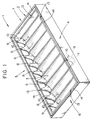
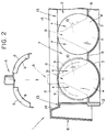
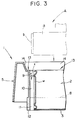
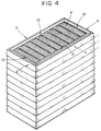
- FIGS. 1 through 4 show a can end tray according to a first embodiment of the present invention.
- a plurality of can end trays according to the first embodiment are stacked to store a stack of layers of horizontal arrays of disk-shaped can ends w.
- each of the can end trays, generally designated by the reference numeral 1, for storing horizontal arrays of can ends w is of an integral structure molded of synthetic resin which comprises a rectangular side wall 2 and a bottom wall joined thereto as can end supports 3.
- the side wall 2 which is of a rectangular shaped when viewed in plan, comprises a pair of upstanding side walls 4,5 extending from front and rear longitudinal ends thereof in confronting relationship to each other, and a pair of upstanding side walls 6,7 extending from transverse side edges thereof in confronting relationship to each other and joined end to end to the side walls 4,5.
- the side walls 4, 5, 6, 7 have a height equal to or larger than the diameter of can ends to be stored in the can end tray 1.
- the can end supports 3 are defined by a plurality of parallel spaced partitions 8 of an inverted U cross-sectional shape for holding a lower portion of each of can ends w in each array, which is about 1/3 of the entire area of the each can end w, between adjacent partitions 8. When arrays of can ends w are placed between the partitions 8, adjacent can end arrays are prevented from contacting each other by the partition 8 positioned therebetween.
- spacers 9 are disposed on inner confronting surfaces of the side walls 4, 5 in longitudinal alignment with the can end supports 3.
- Each of the spacers 9 is substantially in the shape of a triangle and has a first abutting portion 10 for vertically abutting against an upper side surface of the can end at each of the opposite ends of a can end array supported on one of the can end supports 3, and a second abutting portion 11 for horizontally abutting against a lower side surface of the can end at each of the opposite ends of the can end array.
- the first abutting portion 10 is positioned upwardly of, and integral with, the second abutting portion 11. Therefore, the spacers 9 extend diametrically across the can ends at the opposite ends of the can end arrays.
- the can ends w at the opposite ends of the can end arrays are prevented from falling by the first abutting portions 10 and also from swinging by the second abutting portions 11, so that the can ends w can reliably be held on the can end supports 3.
- Gaps x are defined between the can end arrays and the inner surfaces of the side walls 4, 5 in regions where the can ends w are held out of contact by the first abutting portions 10.
- the gaps x allow engaging plates b of a gripper A to be inserted therein when an array of can ends w is to be gripped in its longitudinal direction by a pair of gripper arms a joined at each end thereof to the engaging plates b.
- the gripper arms a are angularly movable toward and away from each other. More specifically, when a robot is used to automatically bring can ends w into the can end tray 1, the gripper A, which is mounted on the robot arm, grips and transfers the can end array onto the can end tray 1. Since a gap v is defined between adjacent can end arrays by a partition 8, when the gripper arms a grip the can end array as indicated by the imaginary lines in FIG.
- the gripper arms a as they move away from each other do not interfere with adjacent can end arrays.
- the gaps x are also defined between the can end array and the inner surfaces of the first side walls 4, 5 by the spacers 9, the engaging plates b do not interfere with the can end array and the first side walls 4, 5 when the gripper arms a grip the can end array as indicated by the imaginary lines in FIG. 2. Consequently, the can end array can smoothly be transferred into the can end tray 1 by the gripper A.
- the first abutting portions 10 are integrally formed with the respective second abutting portions 11. Therefore, when an array of can ends w is to be placed on the can end supports 3, the can ends at the opposite ends of the can end array are guided by the first abutting portions 10 in sliding contact therewith. The can end array can thus smoothly be placed onto the can end supports 3.
- each of the side walls 4, 5, 6, 7 is substantially in the cross-sectional shape of an inverted U that allows the worker to easily hold the side walls 4, 5, 6, 7 to carry the can end tray 1.
- Each of the side walls 4, 5, 6, 7 has a beaded edge 12 on its lower inner portion, the beaded edge 12 projecting downwardly into horizontal alignment with the bottom of the can end supports 3.
- Each of the side walls 4, 5, 6, 7 also has a recess 13 on its upper inner portion above the beaded edge 12 in vertical alignment therewith.
- each of the side walls 4, 5, 6, 7 also has a slanted guide surface 14 extending outwardly of the corresponding recess 13 for smoothly guiding the beaded edge 12 into the recess 13.
- FIG. 5 shows a can end tray 1 according to a second embodiment of the present invention.
- the can end tray 1 shown in FIG. 5 differs from the can end tray 1 shown in FIGS. 1 through 4 in that each of the spacers 9 is substantially of a rectangular shape that extends vertically.
- the spacers 9 do not have the second abutting portions 11 shown in FIGS. 1 and 2, but only have the first abutting portions 10 for vertically abutting against side surfaces of the can ends at the opposite ends of can end arrays.
- the ends on the opposite ends of the can end array are prevented from falling by the first abutting portions 10. Gaps defined between the side wall 2 and the can end arrays permit the gripper A to easily grip the can end arrays.
- a can end tray falling outside the scope of the present invention but using spacers which could equally be employed with the can end tray of the present invention will be described below with reference to FIGS. 6 through 9.
- a plurality of can end trays are stacked to store a stack of layers of horizontal arrays of disk-shaped can ends w.
- each can end tray, generally denoted at 15, for storing horizontal arrays of can ends w comprises a rectangular side wall 16 and a plurality of parallel spaced partitions 17 disposed in and joined to the side wall 16.
- the side wall 16 which is of a rectangular shape when viewed in plan, comprises a pair of upstanding side walls 18, 19 extending from front and rear longitudinal ends thereof in confronting relationship to each other, and a pair of upstanding side walls 20, 21 extending from transverse side edges thereof in confronting relationship to each other and joined end to end to the side walls 18, 19.
- the side walls 18, 19, 20, 21 have a height equal to or larger than the diameter of can ends to be stored in the can end tray 15.
- Each of the partitions 17 is of an inverted V cross-sectional shape, and has opposite ends fixed to inner confronting surfaces of the first side walls 18, 19, respectively. Adjacent two of the partitions 19 can hold an array of can ends w.
- the partitions 19 jointly provide can end supports 22 for supporting can end arrays such that adjacent can end arrays are laterally spaced from, i.e., held out of contact with, each other.
- spacers 23 are disposed on inner confronting surfaces of the side walls 18, 19.
- Each of the spacers 23 is substantially in the shape of an inverted T and has a first abutting portion 24 for vertically abutting against a side surface of the can end at each of the opposite ends of a can end array supported on one of the can end supports 22, and a second abutting portion 25 for horizontally abutting against a lower side surface of the can end at each of the opposite ends of the can end array.
- the first abutting portion 24 is positioned upwardly of, and integral with, the second abutting portion 25. Therefore, the spacers 23 extend diametrically across the can ends at the opposite ends of the can end arrays.
- the can ends w at the opposite ends of the can end arrays are prevented from falling by the first abutting portions 24 and also from swinging by the second abutting portions 25, so that the can ends w can reliably be held on the can end supports 22.
- Gaps y are defined be tween the can end arrays and the inner surfaces of the side walls 18, 19 in regions where the can ends w are held out of contact by the first abutting portions 24.
- the gaps y allow engaginq plates b of a gripper A to be inserted therein when an array of can ends w is to be gripped by a pair of gripper arms a joined to the engaging plates b. More specifically, when a robot is used to automatically bring can ends w into the can end tray 15, the gripper A, which is mounted on the robot arm, grips and transfers the can end array onto the can end tray 15. Since a gap u is defined between adjacent can end arrays by a partition 17, when the gripper arms a grip the can end array as indicated by the imaginary lines in FIG. 7, the gripper arms a do not interfere with adjacent can end arrays.
- the gaps y are also defined between the can end array and the inner surfaces of the first side walls 18, 19 by the spacers 23, the engaging plates b do not interfere with the can end array and the first side walls 18, 19 when the gripper arms a grip the can end array as indicated by the imaginary lines in FIG. 7. Consequently, the can end array can smoothly be transferred into the can end tray 15 by the gripper A.
- each of the second side walls 20, 21 has a pair of spaced pins 26 mounted on an upper surface thereof and a pair of holes 27 defined in a lower surface thereof in vertical alignment with the pins 26, respectively.
- the pins 26 and the holes 27 are positioned at respective corners of the rectangular side wall 16.
- the holes 27 are shaped complementarily to the pins 26 so that the holes 27 can snugly receive the pins 26.
- the can ends on the opposite ends of the can end arrays stored in the can end tray 15 are prevented from falling and being positionally displaced by the spacers 23. Therefore, a number of vertical layers of horizontal arrays of can ends w can be held and conveyed reliably and stably by a plurality of can end trays 15.
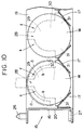
- FIG. 10 shows a can end tray 15 also falling outside the scope of the present invention but having spacers which could be used in the can end tray of the present invention.
- the can end tray 15 shown in FIG. 10 differs from the can end tray 15 shown in FIGS. 6 through 9 in that spacers 28 are disposed on the inner surfaces of the first side walls 18, 19, defining gaps z shaped complementarily to the engaging portions b of the gripper A. More specifically, each of the spacers 28 has a central abutting portion 30 for abutting against a central portion of a can end, and the gaps z are defined by arcuate outer edges of the central abutting portion 30 so as to be positioned at opposite sides of an upper portion of the can end.
- Each of the spacers 28 also has a first abutting portion 29 integral with the central abutting portion 30 for vertically abutting against a side surface of the can end atone end of a can end array, and a second abutting portion 31 integral with the central abutting portion 30 for horizontally abutting against a side surface of the can end.
- the can ends w at the opposite ends of the can end arrays are prevented from falling and swinging by the first abutting portions 29, the second abutting portions 31, and the central abutting portions 30, so that the can ends w can reliably be held on the can end supports 22.
- the gaps z permit the gripper A to grip the can end arrays with ease.
Landscapes
- Engineering & Computer Science (AREA)
- Mechanical Engineering (AREA)
- Stackable Containers (AREA)
Claims (7)
- Dosendeckelschale (1) zur Lagerung mehrerer Reihen von Dosendeckeln (w) während des Transports, bestehend aus:einer im wesentlichen rechteckigen, nach oben stehenden Seitenwand (2) mit einer Höhe wenigstens gleich dem Durchmesser der Dosendeckel;mehreren Dosendeckelträgern (3) auf einem Boden der Schale (1), um die Reihen von Dosendeckeln (w) darauf zu tragen, wobei die Dosendeckelträger (3) mehrere Trennwände (8) haben, um die Reihen von Dosendeckeln (w) beabstandet voneinander zu halten, wenn die Reihen von Dosendeckeln (w) auf den Dosendeckelträgern (3) angeordnet sind; undmehreren Abstandshaltern (9), die an der Seitenwand (2) in Längsrichtung fluchtend mit den Dosendeckelträgern (3) angeordnet sind, um die Seitenwand (2) und die Enden der Reihen von Dosendeckeln (w) voneinander beabstandet zu halten, wenn die Reihen von Dosendeckeln (w) auf den Dosendeckelträgern (3) angeordnet sind, wobei die Abstandshalter (9) so angeordnet sind, daß sie sich, wenn die Reihen von Dosendeckeln (w) auf den Dosendeckelträgern angeordnet sind, über die Dosendeckel (w) an den Enden der Reihen von Dosendeckeln erstrecken und ein Spalt zwischen der Seitenwand (2) und den Dosendeckeln (w) an den Enden der Reihen von Dosendeckeln bilden,dadurch gekennzeichnet, daß
die Seitenwand (2) im Querschnitt im wesentlichen die Form eines umgekehrten U und eine nach unten vorstehende, gefalzte Kante (12) hat, die unten an dem inneren Seitenwandabschnitt ausgebildet ist, und einen Absatz (13), der in einem oberen Abschnitt vertikal fluchtend mit der umgefalzten Kante (12) gebildet ist, wobei sich die umgefalzte Kante (12) und der Absatz (13) vollständig längs der Seitenwand (2) erstrecken. - Dosendeckelschale nach Anspruch 1, bei der jeder der Abstandshalter (9) im wesentlichen rechteckig ist, um Spalte (x) zwischen der Seitenwand (2) und gegenüberliegenden Seitenteilen eines der Dosendeckel (w) an den Enden der Reihen von Dosendeckeln zu bilden.
- Dosendeckelschale nach Anspruch 1, bei der jeder der Abstandshalter (9) einen ersten Anschlag (10) zum vertikalen Anliegen gegen den Dosendeckel (w) an einem der Enden der Reihen von Dosendeckeln aufweist, so daß Spalte (x) zwischen der Seitenwand (2) und gegenüberliegenden Seitenteilen des Dosendeckels (w) gebildet werden, wenn die Reihen von Dosendeckeln auf den Dosendeckelträgern (3) angeordnet sind, und einen zweiten Anschlag (11) zum horizontalen Anliegen gegen den Dosendeckel (w) an einem der Enden von Reihen von Dosendeckeln, wenn die Reihen von Dosendeckeln (w) auf den Dosendeckelträgern (3) angeordnet sind.
- Dosendeckelschale nach Anspruch 3, bei der der erste bzw. zweite Anschlag (10, 11) jedes Abstandshalters (9) zusammen eine im wesentlichen dreieckige Form haben.
- Dosendeckelschale nach Anspruch 3, bei der der erste und zweite Anschlag jedes der Abstandshalter (9) zusammen eine im wesentlichen umgekehrte T-Form haben.
- Dosendeckelschale nach Anspruch 1, bei der jeder der Abstandshalter (9) einen zentralen Anschlag zum Anliegen gegen einen zentralen Abschnitt des Dosendeckels (w) am einen Ende jeder der Reihen von Dosendeckeln hat, so daß Spalte (x) zwischen der Seitenwand (2) und gegenüberliegenden Abschnitten des Dosendeckels (w) gebildet werden.
- Dosendeckelschale nach einem vorhergehenden Anspruch und mit einem Halter (A) mit zwei Haltearmen (a), die relativ zueinander beweglich sind, um die Reihen von Dosendeckeln, eine gleichzeitig, in deren Längsrichtung zu halten, und zwei Greifplatten (b), die mit jedem Ende der Haltearme (a) verbunden sind, um ein Ende jeder der Reihen von Dosendeckeln zu erfassen, wobei
die Trennwände (8) Spalte dazwischen bilden, damit die Haltearme (a), wenn sie sich voneinander entfernen, darin zwischen benachbarten Reihen von Dosendeckeln eingesetzt werden können; und
die Abstandshalter (9) Spalte (x) zwischen der Seitenwand (2) und den Dosendeckeln an den Enden der Reihen von Dosendeckeln bilden, die auf die Dosendeckelträger (3) aufgesetzt sind, damit die Greifplatten (6) darin eingesetzt werden können.
Priority Applications (3)
| Application Number | Priority Date | Filing Date | Title |
|---|---|---|---|
| DE1993611300 DE69311300T2 (de) | 1993-03-01 | 1993-03-01 | Dosendeckelschale |
| EP93301536A EP0613829B1 (de) | 1993-03-01 | 1993-03-01 | Dosendeckelschale |
| US08/231,979 US5394986A (en) | 1993-03-01 | 1994-04-21 | Can end tray |
Applications Claiming Priority (2)
| Application Number | Priority Date | Filing Date | Title |
|---|---|---|---|
| EP93301536A EP0613829B1 (de) | 1993-03-01 | 1993-03-01 | Dosendeckelschale |
| US08/231,979 US5394986A (en) | 1993-03-01 | 1994-04-21 | Can end tray |
Publications (2)
| Publication Number | Publication Date |
|---|---|
| EP0613829A1 EP0613829A1 (de) | 1994-09-07 |
| EP0613829B1 true EP0613829B1 (de) | 1997-06-04 |
Family
ID=26134197
Family Applications (1)
| Application Number | Title | Priority Date | Filing Date |
|---|---|---|---|
| EP93301536A Expired - Lifetime EP0613829B1 (de) | 1993-03-01 | 1993-03-01 | Dosendeckelschale |
Country Status (2)
| Country | Link |
|---|---|
| US (1) | US5394986A (de) |
| EP (1) | EP0613829B1 (de) |
Cited By (3)
| Publication number | Priority date | Publication date | Assignee | Title |
|---|---|---|---|---|
| USD494394S1 (en) | 2003-06-19 | 2004-08-17 | The Procter & Gamble Company | Shelf display divider for absorbent articles |
| US6889856B2 (en) | 2003-06-19 | 2005-05-10 | The Procter & Gamble Company | Shelf tray apparatus for absorbent articles packaged in flexible film |
| US7743932B2 (en) | 2004-01-23 | 2010-06-29 | The Procter & Gamble Company | Shelf display apparatus for absorbent articles packaged in flexible film |
Families Citing this family (24)
| Publication number | Priority date | Publication date | Assignee | Title |
|---|---|---|---|---|
| USD369719S (en) | 1994-09-20 | 1996-05-14 | Kel-Jac Engineering And Plastic Sales, Inc. | Drip tray portion of an upper-front for domestic water coolers |
| US5794796A (en) * | 1994-12-20 | 1998-08-18 | Alpha Enterprises, Inc. | Storage rack for retaining software devices having multiple configurations |
| DE29601187U1 (de) * | 1996-01-25 | 1996-03-28 | FEBRA-Kunststoffe GmbH & Co., 74336 Brackenheim | Ladungsträger mit versteiftem Stapelrand |
| DE19630786A1 (de) * | 1996-07-31 | 1998-02-05 | Woehr Otto Gmbh | Träger für Gegenstände |
| US5882173A (en) * | 1997-09-29 | 1999-03-16 | Ziegler; Charles B. | Golf ball stacking and dispensing apparatus and method |
| DK173696B1 (da) * | 1998-11-24 | 2001-07-02 | Lain Imp Aps | Stabelbar bakke til lagring af flasker/beholdere til opbevaring af væske, fremgangsmåde til lagring af flasker/beholdere til opbevaring af væske i en bakke samt anvendelse af bakken |
| US20040011694A1 (en) * | 2002-07-17 | 2004-01-22 | Hann-Kuang Chen | Plate for placement of cooked and frozen shrimp |
| US6792742B2 (en) | 2002-09-09 | 2004-09-21 | Phoenix Closures, Inc. | Method for storing and/or transporting items |
| USD502626S1 (en) * | 2002-12-31 | 2005-03-08 | Christopher Georgiadis | Storage shelf for discs and cartridges |
| USD498376S1 (en) | 2002-12-31 | 2004-11-16 | Georgiadis Christopher | Storage shelf for discs and cartridges |
| USD498620S1 (en) | 2002-12-31 | 2004-11-23 | Georgiadis Christopher | Storage shelf for discs and cartridges |
| US7367454B1 (en) * | 2003-05-30 | 2008-05-06 | Back Alan W | Insert for retaining vials in a case |
| EP1657170A1 (de) * | 2004-11-15 | 2006-05-17 | Manfred Jacob Kunststofftechnik GmbH & Co. KG | Werkstückträger |
| NL1028793C2 (nl) * | 2005-04-18 | 2006-10-20 | Celema B V | Inrichting voor het in verticale richting transporteren van een reeks achter elkaar geplaatste losse voorwerpen. |
| FR2924105B1 (fr) * | 2007-11-23 | 2009-12-04 | Armor Inox Sa | Unite empilable |
| US8074800B2 (en) * | 2009-03-25 | 2011-12-13 | Osram Sylvania Inc. | Linear lamp cell pack |
| USD665273S1 (en) * | 2009-11-23 | 2012-08-14 | David Ross International S.R.L. | Plastic container for cigarette mouthpieces |
| USD660650S1 (en) * | 2011-11-14 | 2012-05-29 | John Moore | Sandwich display tray |
| USD701418S1 (en) * | 2013-06-06 | 2014-03-25 | American Pan Company | Industrial baguette tray |
| USD833086S1 (en) * | 2015-09-09 | 2018-11-06 | Kyle Hansen | Pet feeder mat |
| USD812476S1 (en) * | 2017-01-27 | 2018-03-13 | Tekni-Plex, Inc. | Packing tray |
| US10421601B2 (en) | 2017-01-27 | 2019-09-24 | Tekni-Plex, Inc. | Processor tray and method of packing |
| USD891274S1 (en) * | 2018-12-07 | 2020-07-28 | Meaty Meats Inc. | Packaging tray |
| US12275578B1 (en) | 2023-12-21 | 2025-04-15 | Solon Manufacturing Company | Product packaging for washers and method of use |
Citations (5)
| Publication number | Priority date | Publication date | Assignee | Title |
|---|---|---|---|---|
| FR1301243A (fr) * | 1961-09-21 | 1962-08-10 | Mauser Kg | Boîte en matière plastique |
| GB1109015A (en) * | 1966-03-04 | 1968-04-10 | Truform Plastics Ltd | Improvements in or relating to containers |
| DE2502813A1 (de) * | 1975-01-24 | 1976-07-29 | Juergens Walter | Transportbehaelter |
| EP0312854A1 (de) * | 1987-10-21 | 1989-04-26 | Stucki Kunststoffwerk und Werkzeugbau GmbH. | Zubringevorrichtung für Werkstücke |
| DE3934800A1 (de) * | 1988-11-30 | 1990-05-31 | Schaefer Gmbh Fritz | Stapeltransportkasten aus metallischem schichtmaterial |
Family Cites Families (14)
| Publication number | Priority date | Publication date | Assignee | Title |
|---|---|---|---|---|
| CA531715A (en) * | 1956-10-16 | R. Polglase Thomas | Shipping container for heavy spools | |
| US1433560A (en) * | 1919-04-24 | 1922-10-31 | United Shoe Machinery Corp | Heel-lift container |
| US3306462A (en) * | 1965-03-31 | 1967-02-28 | Cruz Edward Da | Storage case for disk-shaped objects |
| US3398828A (en) * | 1967-09-20 | 1968-08-27 | Bausch & Lomb | Holding device for cylindrical objects |
| US3591032A (en) * | 1969-04-14 | 1971-07-06 | Baxter Co | Receptacle-pallet |
| US3740238A (en) * | 1971-01-04 | 1973-06-19 | S Graham | Stackable cookie package and tray |
| US3856137A (en) * | 1971-03-03 | 1974-12-24 | Union Carbide Corp | Display tray with merchandise-mounted card packages |
| US3926305A (en) * | 1973-07-12 | 1975-12-16 | Fluoroware Inc | Wafer basket |
| DE3334769A1 (de) * | 1983-09-26 | 1985-04-11 | Karges-Hammer-Maschinen Gmbh & Co Kg, 3300 Braunschweig | Transportbehaelter sowie verfahren und vorrichtung zum transportieren von dosendeckelstapeln in dem transportbehaelter |
| DE8704953U1 (de) * | 1987-04-02 | 1987-05-27 | Karges-Hammer-Maschinen GmbH & Co KG, 38122 Braunschweig | Transportbehälter für Deckelstränge |
| DE68917639T2 (de) * | 1988-05-18 | 1995-02-16 | Fleetwood Syst Inc | Automatisches Kastenbelade-, -entlade- und -lagerungssystem. |
| JPH0315341A (ja) * | 1989-06-12 | 1991-01-23 | Sukairaaku:Kk | 野菜類の鮮度保持剤とその用法 |
| JPH03187852A (ja) * | 1989-12-15 | 1991-08-15 | Kirin Brewery Co Ltd | 層状同一形状物搬送容器及び同容器を使用した層状同一形状物の供給方法 |
| US5207727A (en) * | 1990-07-06 | 1993-05-04 | Rapsco Incorporated | Can end handling system |
-
1993
- 1993-03-01 EP EP93301536A patent/EP0613829B1/de not_active Expired - Lifetime
-
1994
- 1994-04-21 US US08/231,979 patent/US5394986A/en not_active Expired - Fee Related
Patent Citations (5)
| Publication number | Priority date | Publication date | Assignee | Title |
|---|---|---|---|---|
| FR1301243A (fr) * | 1961-09-21 | 1962-08-10 | Mauser Kg | Boîte en matière plastique |
| GB1109015A (en) * | 1966-03-04 | 1968-04-10 | Truform Plastics Ltd | Improvements in or relating to containers |
| DE2502813A1 (de) * | 1975-01-24 | 1976-07-29 | Juergens Walter | Transportbehaelter |
| EP0312854A1 (de) * | 1987-10-21 | 1989-04-26 | Stucki Kunststoffwerk und Werkzeugbau GmbH. | Zubringevorrichtung für Werkstücke |
| DE3934800A1 (de) * | 1988-11-30 | 1990-05-31 | Schaefer Gmbh Fritz | Stapeltransportkasten aus metallischem schichtmaterial |
Cited By (3)
| Publication number | Priority date | Publication date | Assignee | Title |
|---|---|---|---|---|
| USD494394S1 (en) | 2003-06-19 | 2004-08-17 | The Procter & Gamble Company | Shelf display divider for absorbent articles |
| US6889856B2 (en) | 2003-06-19 | 2005-05-10 | The Procter & Gamble Company | Shelf tray apparatus for absorbent articles packaged in flexible film |
| US7743932B2 (en) | 2004-01-23 | 2010-06-29 | The Procter & Gamble Company | Shelf display apparatus for absorbent articles packaged in flexible film |
Also Published As
| Publication number | Publication date |
|---|---|
| EP0613829A1 (de) | 1994-09-07 |
| US5394986A (en) | 1995-03-07 |
Similar Documents
| Publication | Publication Date | Title |
|---|---|---|
| US5394986A (en) | Can end tray | |
| US4718552A (en) | Disk shipper and transfer tray | |
| US5348151A (en) | Low profile disk carrier | |
| US5423422A (en) | Flat panel display container | |
| US6032801A (en) | Pallet system | |
| CA1291080C (en) | Disk shipper | |
| US4798305A (en) | Adjustable shipping tray | |
| US20140050556A1 (en) | Apparatus and method for aligning and holding egg cartons | |
| US6315156B1 (en) | Tape-form packaging system and apparatus for effecting assembly and disassembly thereof | |
| US4852737A (en) | Packaging system for electrical connectors | |
| US3435949A (en) | Magazine for integrated circuit modules | |
| US5154294A (en) | Videocassette tray | |
| JPH0656168A (ja) | 特有のポケットを有する電子部品輸送テープ | |
| JP7773190B2 (ja) | システム | |
| US4632246A (en) | Package for card edge connectors | |
| CA1330767C (en) | Bottle carrier assembly | |
| US11377282B2 (en) | Use of a tray for conveying pouches for flexible containers and methods and machines using such tray | |
| EP0610100B1 (de) | Schale zum Lagern und Stapeln von Gegenständen | |
| JP2550971Y2 (ja) | 缶蓋搬送用トレー | |
| JP2008100693A (ja) | 収納トレイ | |
| JPH061285U (ja) | コンデンサ用容器 | |
| JPS63178972A (ja) | 製品収納容器 | |
| JP2549910Y2 (ja) | 缶蓋搬送用トレー | |
| GB2274833A (en) | Storage and/or transit stacking of articles | |
| JPH02109827A (ja) | 包装機械へのブランク装入装置 |
Legal Events
| Date | Code | Title | Description |
|---|---|---|---|
| PUAI | Public reference made under article 153(3) epc to a published international application that has entered the european phase |
Free format text: ORIGINAL CODE: 0009012 |
|
| AK | Designated contracting states |
Kind code of ref document: A1 Designated state(s): DE FR GB |
|
| 17P | Request for examination filed |
Effective date: 19950206 |
|
| 17Q | First examination report despatched |
Effective date: 19950922 |
|
| GRAG | Despatch of communication of intention to grant |
Free format text: ORIGINAL CODE: EPIDOS AGRA |
|
| GRAH | Despatch of communication of intention to grant a patent |
Free format text: ORIGINAL CODE: EPIDOS IGRA |
|
| GRAH | Despatch of communication of intention to grant a patent |
Free format text: ORIGINAL CODE: EPIDOS IGRA |
|
| GRAA | (expected) grant |
Free format text: ORIGINAL CODE: 0009210 |
|
| AK | Designated contracting states |
Kind code of ref document: B1 Designated state(s): DE FR GB |
|
| REF | Corresponds to: |
Ref document number: 69311300 Country of ref document: DE Date of ref document: 19970710 |
|
| ET | Fr: translation filed | ||
| PGFP | Annual fee paid to national office [announced via postgrant information from national office to epo] |
Ref country code: FR Payment date: 19980211 Year of fee payment: 6 |
|
| PGFP | Annual fee paid to national office [announced via postgrant information from national office to epo] |
Ref country code: GB Payment date: 19980226 Year of fee payment: 6 |
|
| PGFP | Annual fee paid to national office [announced via postgrant information from national office to epo] |
Ref country code: DE Payment date: 19980331 Year of fee payment: 6 |
|
| PLBE | No opposition filed within time limit |
Free format text: ORIGINAL CODE: 0009261 |
|
| STAA | Information on the status of an ep patent application or granted ep patent |
Free format text: STATUS: NO OPPOSITION FILED WITHIN TIME LIMIT |
|
| 26N | No opposition filed | ||
| PG25 | Lapsed in a contracting state [announced via postgrant information from national office to epo] |
Ref country code: DE Free format text: LAPSE BECAUSE OF THE APPLICANT RENOUNCES Effective date: 19990205 |
|
| PG25 | Lapsed in a contracting state [announced via postgrant information from national office to epo] |
Ref country code: GB Free format text: LAPSE BECAUSE OF NON-PAYMENT OF DUE FEES Effective date: 19990301 |
|
| GBPC | Gb: european patent ceased through non-payment of renewal fee |
Effective date: 19990301 |
|
| PG25 | Lapsed in a contracting state [announced via postgrant information from national office to epo] |
Ref country code: FR Free format text: LAPSE BECAUSE OF NON-PAYMENT OF DUE FEES Effective date: 19991130 |
|
| REG | Reference to a national code |
Ref country code: FR Ref legal event code: ST |