EP0614687B1 - Procédé et dispositif pour récupérer des mélanges de vapeur à plusieurs composants - Google Patents
Procédé et dispositif pour récupérer des mélanges de vapeur à plusieurs composants Download PDFInfo
- Publication number
- EP0614687B1 EP0614687B1 EP93114854A EP93114854A EP0614687B1 EP 0614687 B1 EP0614687 B1 EP 0614687B1 EP 93114854 A EP93114854 A EP 93114854A EP 93114854 A EP93114854 A EP 93114854A EP 0614687 B1 EP0614687 B1 EP 0614687B1
- Authority
- EP
- European Patent Office
- Prior art keywords
- vapor
- cold trap
- trap
- valve
- conduit
- Prior art date
- Legal status (The legal status is an assumption and is not a legal conclusion. Google has not performed a legal analysis and makes no representation as to the accuracy of the status listed.)
- Expired - Lifetime
Links
Images
Classifications
-
- B—PERFORMING OPERATIONS; TRANSPORTING
- B01—PHYSICAL OR CHEMICAL PROCESSES OR APPARATUS IN GENERAL
- B01D—SEPARATION
- B01D8/00—Cold traps; Cold baffles
-
- A—HUMAN NECESSITIES
- A61—MEDICAL OR VETERINARY SCIENCE; HYGIENE
- A61L—METHODS OR APPARATUS FOR STERILISING MATERIALS OR OBJECTS IN GENERAL; DISINFECTION, STERILISATION OR DEODORISATION OF AIR; CHEMICAL ASPECTS OF BANDAGES, DRESSINGS, ABSORBENT PADS OR SURGICAL ARTICLES; MATERIALS FOR BANDAGES, DRESSINGS, ABSORBENT PADS OR SURGICAL ARTICLES
- A61L2/00—Disinfection or sterilisation of materials or objects, in general; Accessories therefor
- A61L2/16—Disinfection or sterilisation of materials or objects, in general; Accessories therefor using chemical substances
- A61L2/20—Gaseous substances, e.g. vapours
- A61L2/206—Ethylene oxide
-
- Y—GENERAL TAGGING OF NEW TECHNOLOGICAL DEVELOPMENTS; GENERAL TAGGING OF CROSS-SECTIONAL TECHNOLOGIES SPANNING OVER SEVERAL SECTIONS OF THE IPC; TECHNICAL SUBJECTS COVERED BY FORMER USPC CROSS-REFERENCE ART COLLECTIONS [XRACs] AND DIGESTS
- Y02—TECHNOLOGIES OR APPLICATIONS FOR MITIGATION OR ADAPTATION AGAINST CLIMATE CHANGE
- Y02P—CLIMATE CHANGE MITIGATION TECHNOLOGIES IN THE PRODUCTION OR PROCESSING OF GOODS
- Y02P70/00—Climate change mitigation technologies in the production process for final industrial or consumer products
- Y02P70/10—Greenhouse gas [GHG] capture, material saving, heat recovery or other energy efficient measures, e.g. motor control, characterised by manufacturing processes, e.g. for rolling metal or metal working
Definitions
- This invention relates to a method and apparatus for recovering multicomponent vapor mixtures, and more particularly for recovering vapor mixtures used in sterilizing processes.
- a pressure and vacuum sealed enclosure or vessel is loaded with articles to be sterilized.
- the sterilizer and its contents are preconditioned by evacuation down to a moderately low pressure level, typically about 75 Torr (26 in. Hg Vac.), backfilled with low pressure steam and then re-evacuated. This evacuation-backfill cycle is repeated several times to remove most of the air and to prewarm and moisten the articles to be sterilized.
- a sterilant gas typically a 12-88 weight percent mixture of ethylene oxide and CFC-12 (dichlorodifluoromethane), is introduced into the preconditioned and evacuated enclosure until the pressure reaches approximately 11 ⁇ 2 atmospheres. This condition is held for a predetermined period adequate to sterilize the articles in the enclosure.
- the now moist sterilant gas was removed from the enclosure by evacuation and was either discharged into the atmosphere or the sewer. This practice created serious problems.
- ethylene oxide by itself is flammable, explosive and toxic, while the blanket vapor, dichlorodifluoromethane or CFC-12 damages the ozone layer in the atmosphere and is a global warming gas. Therefore it became desirable, if not essential, to provide a process for capturing and recovering at least the CFC and preferably both components of the mixture.
- cryogenic condensing and separation of recyclable materials was another possible approach to the problem of handling vapor mixtures.
- expendable cryogens e.g. liquid nitrogen
- Such cryogens also require supplemental separation techniques particularly for removal of components which freeze well above nitrogen's boiling point.
- Catalytic destruction of combustible components is another vapor handling technique, but catalytic disposer units can only remove combustible portions of mixtures and therefor must be used in combination with other apparatus such as membranes or scrubbers. Also, they cannot dispose of nor convert CFCs into benign materials, and the method in general requires a high energy input.
- Chemical (typically acid) scrubbing of vapors to remove and render benign selected components is a well know process used for vapor control, but scrubbers remove only those components with which the chemical reacts.
- Other components such as halocarbons require additional apparatus for recovery.
- Another object of the invention is to provide an apparatus for recovering multicomponent vapor mixtures which significantly reduces the required energy input (by at least 50% compared to a single cryogenic temperature capture system) while retaining a capture efficiency of at least 99% for a vapor mixture such as OxyFume-12 (88% R-12 and 12% by weight ethylene oxide) starting at a dew point as low as -15 degrees C and mixed with water vapor and air.
- a vapor mixture such as OxyFume-12 (88% R-12 and 12% by weight ethylene oxide) starting at a dew point as low as -15 degrees C and mixed with water vapor and air.
- Another object of the invention is to maintain a safe balance between the blanketing vapor and the toxic or hazardous components of a mixture, e.g. the R-12 and ethylene oxide of the above example, during all stages of capture.
- a mixture e.g. the R-12 and ethylene oxide of the above example
- Other objects of the invention are to provide a method and apparatus for recovering multicomponent vapor mixtures which: (1) separates benign non-condensible gases (e.g. air) from recyclable materials and safely disposes of such gases without an unacceptable release of captured components; (2) extracts hazardous, environmentally undesirable or valuable vapors from their point of use and transfers them in either liquid or vapor phases as required, from the recovery system to vessels for transport and reclamation, without using mechanical pumping means that might introduce contamination; (3) provides a capture efficiency of at least 99% for a mixture comprising 88% (weight) CFC-12 and 12% ethylene oxide; and (4) is able to operate properly under any of three distinct modes: (a) Evacuating the source enclosure from an initial pressure of one to two atmospheres, when it contains almost all condensible materials with little non-condensible air present, down to a vacuum; (b) Pumping out (evacuating) the source enclosure after it has been backfilled with air, the air serving as a carrier gas for both the residual vapors in the apparatus and vapors des
- an apparatus which can be connected directly to a chamber such as a medical instrument sterilizer which contains the vapor mixture that is to be recovered.
- An outlet conduit from the mixture chamber or sterilizer has a first branch conduit through a capture valve to a first level cooling tank or cold trap. This outlet conduit also connects to one side of a precondition valve whose other side is connected to a vacuum pump. Between the precondition valve and the vacuum pump is another branch conduit connected to a second cooling tank or cold trap, preferably at a lower level. The upper end of the first cooling tank or cold trap is connected by a vapor transporting conduit to the second cooling tank.
- the lower end of the first cooling tank is connected to a conduit which transports condensate by gravity flow to the second cooling tank.
- the first cooling trap has an internal coil or cooling surface which is cooled by a first outside refrigerant source to an operating temperature range of -5 to -40 degrees C and the second cold trap assembly has an internal coil which is cooled to a range of -95 to -110 degrees C.
- Volatile vapors start condensing on the coil of the first cold trap and the steam condenses as frost.
- the sterilant vapor a mixture of two compounds, partially condenses within the first cold trap.
- the condensate formed in the first cold trap is drained into the reservoir section of the second trap.
- the colder coil or cryosurface in the second trap induces flow of uncondensed vapor from the first cold trap to the second cold trap and this vapor is ultimately condensed on the colder coil.
- the condensed vapor from this coil blends with the condensate from the first trap in the reservoir of the second trap and hence the condensed sterilant mixture promptly returns to its original safe ratio of the blanket material, CFC-12, to ethylene oxide.
- this reconstituted mixture can be transported for reuse without being dumped into the atmosphere.
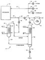
- a recovery apparatus 10 which withdraws a multicomponent vapor mixture from a processing chamber which, in the example shown, is a gas sterilizer 12.
- a gas sterilizer 12 Such sterilizers are commonly used in hospitals and laboratories for sterilizing surgical implements and the like.
- the sterilizer is filled with a sterilant gas, typically a 12-88 weight percent mixture of moist ethylene oxide and CFC-12 (dichlorodifluoromethane).
- a sterilant gas typically a 12-88 weight percent mixture of moist ethylene oxide and CFC-12 (dichlorodifluoromethane).
- the apparatus 10 functions to remove and recover the gas mixture from the sterilizer and to provide a condensate end product comprised of the original mixture constituents in substantially the same proportions as when first supplied to the sterilizer.
- an input conduit 14 Connected to the sterilizer 12 is an input conduit 14 which in turn is connected to three supply inputs 16, 18 and 20 for admitting either steam, air or sterilant to the sterilizer.
- Each input has its own supply valve 22, 24 or 26 for controlling flow from a separate supply source (not shown).
- An output fluid conduit 28 extends from the sterilizer to carry the moist gas mixture from it.
- This conduit is connected through a first or precondition valve 38 to a vacuum pump 40.
- Branching from conduit 28 at a junction 29 is a conduit 30 which passes through a controllable second or capture valve 32 and extends to a first cooling chamber or trap 34.
- This trap has within it a coil 36 providing a cooling surface, the ends of which extend out from the cooling trap 34.
- the ends of the coil 36 are connected to a suitable refrigerant source (not shown) which is capable of supplying refrigerant to the coil in a temperature range of -5 to -40 degrees C.
- a suitable refrigerant source may be an apparatus such as shown in U.S. Patent No. 3,768,273.
- the conduit 28 is connected through the precondition valve 38 and thereafter to the vacuum pump 40.
- a branch conduit 42 which extends through a third valve 44 from a second cooling chamber or trap 46.
- This trap is preferably situated lower than the first cooling trap 34.
- a cooling coil 48 whose ends extend outside the trap to a refrigeration source (not shown) which furnishes refrigerant to the cool 48 at a temperature range of -95 to -110 degrees C.
- a refrigeration source may be of the type shown in the previously mentioned U.S. Patent.
- a conduit 50 for carrying vapor from cooling trap 34 is connected to the upper end thereof and extends to cooling trap 46, preferably at a location just below its cooling coil 48.
- a conduit 52 is connected for carrying condensate therefrom.
- the other end of this condensate conduit is connected to the lower, colder cooling trap 46 near its bottom or reservoir end so that condensate will flow from trap 34 to trap 46 by gravity.
- Sterilization process For preconditioning, sterilizer 12 first is evacuated by vacuum pump 40 via conduit 28 and through precondition valve 38. Following this, valve 38 then is closed. Steam is now admitted into sterilizer 12 via conduits 16 and 14 through valve 22. When sterilizer 12 reaches a predetermined pressure, steam valve 22 is closed and preconditioning valve 38 is reopened for a repeat of the evacuation step. After several such cycles and then a last evacuation step, valve 26 opens to admit sterilant gas into sterilizer 12 via conduits 20 and 14 until the sterilant's pressure reaches a predetermined pressure equivalent to a dew point of about -10 to -15 degrees C. The gas then sterilizes the implements or products therein. After the sterilization cycle, the recovery system begins its capture of the gases and vapors for reclaiming and recycling.
- Capture System Preconditioning During or before the sterilizer's preconditioning and sterilizing steps, trapping (condensing) coils or surfaces 36 and 48 in cold trap assemblies 34 and 46 are precooled to operating temperature levels, between -5 to -40 degrees C and -95 to -110 degrees C respectively. Vacuum pump 40 purges air from cold trap assemblies 34 and 46 via conduit 42 and evacuation valve 44 any time a significant amount of air accumulates.
- Air Purge Accumulated air is detected by (a) measuring the temperature of cryogenic surface 48, (b) calculating the sterilant's vapor pressure at this temperature and (c) comparing this pressure to the pressure within cold trap assembly 46. The difference between the pressure in the cold trap and the vapor pressure at cryosurface temperature of cryosurface 48 indicates the partial pressure of air present. Vacuum pump 40 withdraws the air via conduit 42 and through evacuation valve 44 until the two pressures are near each other. The evacuated air carries only trace amounts of sterilant vapor out of cold trap assembly 46 to the vacuum pump 40 because of the cryogenic temperature and geometry of the cryosurface 48 which permits only minimal bypass flow.
- Capture cycle After the sterilizer 12 completes its sterilization cycle and with supply valves 22, 24 and 26 preconditioning valve 38 closed, the capture valve 32 is opened. A mixture of moist sterilant vapor and residual air flows from the sterilizer 12 via conduits 28 and 30 into cold trap assembly 34 which is at low pressure. Volatile vapors start condensing on the cryosurface 36. Almost all of the steam (water vapor) condenses in the form of frost on surface 36. The sterilant vapor, a mixture of two compounds which do not form an azeotrope, partially condenses.
- the condensate is richer in the higher boiling component, ethylene oxide, and vapor is richer in the more volatile (lower boiling) component, typically a blanketing vapor such as CFC-12.
- the condensate formed in cold trap 34 drains via conduit 52 to the reservoir section of cold trap 46.
- Cryosurface 48 in cold trap 46 which is at a very low temperature, induces flow of the uncondensed vapor and residual air from cold trap 34 via conduit 50 to cold trap 46. There this vapor condenses on cryosurface 48 and drops into and blends with the condensate from cold trap 34 in the reservoir section of cold trap 46.
- the condensed sterilant mixture promptly returns to its original safe ratio of CFC-12 to ethylene oxide.
- Air Pulse Capture valve 32 is closed to isolate sterilizer 12 from the capture system. Air admitting valve 24 is opened to backfill sterilizer 12 with air to nearly one atmosphere pressure and then is closed. Sterilant vapor and moisture, now desorbing from the sterilized products and the walls of the sterilizer 12, diffuse into the air. After a predetermined time, air admitting valve 24 is closed and capture valve 32 is opened. The capture system then removes this air and moist sterilant mixture in the same manner as described above except that the fluid flowing is now principally air. Cold trap 34 precools this fluid stream to almost the temperature of cryosurface 36 with little or no condensation of volatiles because of their low partial pressure.
- Vacuum pump 40 removes the air, now essentially free of sterilant, via conduit 42 and through evacuation valve 44. A predetermined number of these air pulse cycles may be repeated or an air wash cycle may follow.
- capture valve 32 and air purge valve 44 are closed to isolate the captured moist sterilant condensate within the capture system.
- the condensate in the reservoir section of cold trap 46 and cryosurfaces 36 and 48 are heated to above room temperature until the pressure of the condensate increases to a suitable level for transfer.
- the heat source can be electric resistance heaters.
- a preferred embodiment is a modified version of U.S. Patent No. 4,535,597. This arrangement utilizes heat rejected from the cooling system to quickly reheat a cryogenic surface. (See Cooling System described below).
- a transport cylinder not shown, is connected to drain valve 56. Drain valve 56 and the cylinder's valve are opened to allow transfer of the now warm (moist and used) sterilant liquid via conduit 54 from the capture system to the cylinder. Drain valve 56 and the cylinder valve are closed and the capture cycle is ready to be repeated.
Landscapes
- Chemical & Material Sciences (AREA)
- Chemical Kinetics & Catalysis (AREA)
- Health & Medical Sciences (AREA)
- General Chemical & Material Sciences (AREA)
- Epidemiology (AREA)
- Life Sciences & Earth Sciences (AREA)
- Animal Behavior & Ethology (AREA)
- General Health & Medical Sciences (AREA)
- Public Health (AREA)
- Veterinary Medicine (AREA)
- Apparatus For Disinfection Or Sterilisation (AREA)
- Vaporization, Distillation, Condensation, Sublimation, And Cold Traps (AREA)
Claims (12)
- Appareil pour régénérer un mélange de composés chimiques utilisé à l'intérieur d'une chambre comme un mélange de vapeurs contenant des proportions prédéterminées desdits composés, ledit appareil comprenant :- une canalisation principale de fluide (28) qui part de ladite chambre (12), traverse une première vanne (38) et est raccordée en son extrémité extérieure à une pompe à vide (40),- une première branche de canalisation (30) qui part de ladite canalisation principale par une seconde vanne (32),- un premier piège froid (34) raccordé à ladite première branche de canalisation,- un premier moyen formant cryosurface (36), placé à l'intérieur dudit premier piège froid et raccordé à une première source de réfrigérant à basse température,- un second piège froid (46) et un second moyen formant cryosurface (48) placé à l'intérieur dudit second piège froid et raccordé à une seconde source de réfrigérant à basse température qui fait circuler du réfrigérant vers ce moyen à une température plus basse que ladite première source de réfrigérant,- une seconde branche de canalisation (42) qui part dudit second piège froid, traverse une troisième vanne (44) et va jusqu'à ladite canalisation principale,- une canalisation à vapeur (50) qui relie entre eux lesdits pièges froids pour faire passer la vapeur dudit premier piège audit second piège, et- une canalisation à condensat (52) raccordée à l'extrémité inférieure dudit premier piège froid pour acheminer le condensat vers ledit second piège froid.
- Appareil selon la revendication 1, dans lequel ledit mélange de vapeurs est composé d'un matériau stérilisant et d'un matériau tampon.
- Appareil selon la revendication 2, dans lequel ledit mélange de vapeurs contient presque 12% en poids d'oxyde d'éthylène et environ 88% en poids de CFC-12 (dichlorodifluorométhane).
- Appareil selon la revendication 1, dans lequel ladite première source de réfrigérant maintient ledit premier moyen formant cryosurface dans une plage de températures allant de -5°C à -40°C et ladite seconde source de réfrigérant maintient ledit second moyen formant cryosurface dans une plage de températures allant de -95°C à -110°C.
- Appareil selon la revendication 1, dans lequel lesdits premier et second pièges froids comprennent chacun des chambres cylindriques verticales et ledit second piège est situé à un niveau en-dessous de celui dudit premier piège.
- Appareil selon la revendication 5, dans lequel lesdits premier et second moyens formant cryosurfaces sont des serpentins de canalisation de fluide situés respectivement à l'intérieur desdits premier et second pièges froids.
- Appareil selon la revendication 2, comprenant :- une canalisation d'entrée (14) raccordée à ladite chambre,- des canalisations d'alimentation (16, 18, 20) raccordées à ladite canalisation d'entrée et partant de sources séparées de vapeur d'eau , d'air et de stérilisant, et- une vanne d'arrêt dans chaque canalisation d'alimentation.
- Procédé pour régénérer un mélange de vapeurs de composés chimiques utilisé dans une chambre fermée, ledit procédé comprenant les étapes consistant à :- prévoir un appareil de récupération pour extraire à l'aide d'une pompe à vide le mélange de ladite chambre et l'envoyer dans un premier piège froid,- refroidir le mélange dans ledit premier piège froid jusqu'à un premier niveau de température qui provoque une condensation partielle du mélange,- évacuer le condensat dudit premier piège froid à un second piège froid,- entrainer la vapeur dudit premier piège froid audit second piège froid,- refroidir ledit second piège froid jusqu'à un niveau de température qui est plus bas que celui dudit premier piège froid, de sorte que toute la vapeur contenue dans ce dernier se condense et se combine avec le condensat provenant dudit premier piège froid, et- évacuer le condensat combiné dudit second piège froid en vue de son stockage ou de sa ré-utilisation.
- Procédé selon la revendication 8, dans lequel ledit premier piège froid est refroidi dans une plage de températures comprise entre -5 et -40°C et ledit second piège froid est refroidi dans une plage de températures comprise entre -95 et -110°C.
- Procédé selon la revendication 8, dans lequel ladite chambre fermée est un stérilisateur et ledit mélange de vapeurs est composé d'oxyde d'éthylène et de CFC-12.
- Procédé selon la revendication 8, comprenant les étapes supplémentaires consistant à :- chauffer le condensat combiné au-dessus de la température ambiante jusqu'à ce que la pression du condensat atteigne un niveau approprié pour le transfert vers un conteneur de stockage.
- Procédé selon la revendication 8, comprenant les étapes consistant à :- prévoir une vanne pour isoler la chambre fermée de l'appareil de régénération,- fermer ladite vanne quand toute la vapeur a été retirée de ladite chambre,- permettre à de la vapeur et de l'humidité supplémentaires de se désorber des produits et des parois à l'intérieur de ladite chambre pendant un laps de temps prédéterminé,- ouvrir ladite vanne après ledit laps de temps,- faire entrer une impulsion d'air dans ladite chambre pour en retirer la vapeur et de l'humidité supplémentaires désorbées et les envoyer dans l'installation de régénération pour condenser la vapeur supplémentaire.
Applications Claiming Priority (2)
| Application Number | Priority Date | Filing Date | Title |
|---|---|---|---|
| US28742 | 1993-03-09 | ||
| US08/028,742 US5261250A (en) | 1993-03-09 | 1993-03-09 | Method and apparatus for recovering multicomponent vapor mixtures |
Publications (2)
| Publication Number | Publication Date |
|---|---|
| EP0614687A1 EP0614687A1 (fr) | 1994-09-14 |
| EP0614687B1 true EP0614687B1 (fr) | 1996-05-29 |
Family
ID=21845167
Family Applications (1)
| Application Number | Title | Priority Date | Filing Date |
|---|---|---|---|
| EP93114854A Expired - Lifetime EP0614687B1 (fr) | 1993-03-09 | 1993-09-15 | Procédé et dispositif pour récupérer des mélanges de vapeur à plusieurs composants |
Country Status (5)
| Country | Link |
|---|---|
| US (1) | US5261250A (fr) |
| EP (1) | EP0614687B1 (fr) |
| JP (1) | JPH06269605A (fr) |
| CA (1) | CA2104055C (fr) |
| DE (1) | DE69302893T2 (fr) |
Families Citing this family (40)
| Publication number | Priority date | Publication date | Assignee | Title |
|---|---|---|---|---|
| US5540057A (en) * | 1995-06-30 | 1996-07-30 | Praxair Technology, Inc. | Volatile organic compounds recovery from vent gas streams |
| US5617727A (en) * | 1996-05-24 | 1997-04-08 | Richard R. Zito R & D Corp. | Controlled multiple storage vessel gas trap |
| US5799509A (en) * | 1997-08-22 | 1998-09-01 | The Boc Group, Inc. | Multi-component recovery apparatus and method |
| US6094922A (en) * | 1998-09-09 | 2000-08-01 | Ziegler; Alex R. | Vacuum-insulated refrigerant line for allowing a vaccum chamber system with water-vapor cryocoil compressor to be locatable outside cleanroom |
| US6383257B1 (en) | 2000-04-04 | 2002-05-07 | Air Products And Chemicals, Inc. | Reclamation and separation of perfluorocarbons using condensation |
| US7611903B2 (en) * | 2002-09-11 | 2009-11-03 | Lawrence Livermore National Security, Llc | System for trapping and storing gases for subsequent chemical reduction to solids |
| US8664124B2 (en) | 2005-10-31 | 2014-03-04 | Novellus Systems, Inc. | Method for etching organic hardmasks |
| US8110493B1 (en) | 2005-12-23 | 2012-02-07 | Novellus Systems, Inc. | Pulsed PECVD method for modulating hydrogen content in hard mask |
| US7981810B1 (en) | 2006-06-08 | 2011-07-19 | Novellus Systems, Inc. | Methods of depositing highly selective transparent ashable hardmask films |
| US7666369B2 (en) | 2006-09-29 | 2010-02-23 | Tyco Healthcare Group Lp | System and method for recycling sterilant gas |
| US8268238B2 (en) | 2006-09-29 | 2012-09-18 | Tyco Healthcare Group Lp | System and method for recycling sterilant gas |
| US7981777B1 (en) | 2007-02-22 | 2011-07-19 | Novellus Systems, Inc. | Methods of depositing stable and hermetic ashable hardmask films |
| US7915166B1 (en) | 2007-02-22 | 2011-03-29 | Novellus Systems, Inc. | Diffusion barrier and etch stop films |
| US8236253B2 (en) * | 2007-04-30 | 2012-08-07 | Midmark Corporation | Portable sterilizing apparatus for surgical and dental instruments |
| US8962101B2 (en) | 2007-08-31 | 2015-02-24 | Novellus Systems, Inc. | Methods and apparatus for plasma-based deposition |
| USD598565S1 (en) | 2008-04-30 | 2009-08-18 | Midmark Corporation | External condensation tank for a sterilizer |
| USD598564S1 (en) | 2008-04-30 | 2009-08-18 | Midmark Corporation | Handle for portable sterilizing apparatus |
| USD603053S1 (en) | 2008-04-30 | 2009-10-27 | Midmark Corporation | Portable sterilizing apparatus |
| US7820556B2 (en) * | 2008-06-04 | 2010-10-26 | Novellus Systems, Inc. | Method for purifying acetylene gas for use in semiconductor processes |
| US8435608B1 (en) | 2008-06-27 | 2013-05-07 | Novellus Systems, Inc. | Methods of depositing smooth and conformal ashable hard mask films |
| US7955990B2 (en) * | 2008-12-12 | 2011-06-07 | Novellus Systems, Inc. | Method for improved thickness repeatability of PECVD deposited carbon films |
| US8563414B1 (en) | 2010-04-23 | 2013-10-22 | Novellus Systems, Inc. | Methods for forming conductive carbon films by PECVD |
| US10118122B2 (en) * | 2011-08-29 | 2018-11-06 | The Boeing Company | CO2 collection methods and systems |
| US9205357B2 (en) | 2012-03-29 | 2015-12-08 | The Boeing Company | Carbon dioxide separation system and method |
| US9156703B2 (en) | 2012-03-30 | 2015-10-13 | The Boeing Company | System and method for producing carbon dioxide |
| SG195494A1 (en) | 2012-05-18 | 2013-12-30 | Novellus Systems Inc | Carbon deposition-etch-ash gap fill process |
| US9777628B2 (en) | 2012-08-23 | 2017-10-03 | The Boeing Company | System and method for processing greenhouse gases |
| US9103549B2 (en) | 2012-08-23 | 2015-08-11 | The Boeing Company | Dual stream system and method for producing carbon dioxide |
| US9362133B2 (en) | 2012-12-14 | 2016-06-07 | Lam Research Corporation | Method for forming a mask by etching conformal film on patterned ashable hardmask |
| US9073001B2 (en) | 2013-02-14 | 2015-07-07 | The Boeing Company | Monolithic contactor and associated system and method for collecting carbon dioxide |
| US9304396B2 (en) | 2013-02-25 | 2016-04-05 | Lam Research Corporation | PECVD films for EUV lithography |
| US9302021B2 (en) | 2013-08-30 | 2016-04-05 | American Sterilizer Company | Method of performing sterilization cycle |
| US9320387B2 (en) | 2013-09-30 | 2016-04-26 | Lam Research Corporation | Sulfur doped carbon hard masks |
| US9589799B2 (en) | 2013-09-30 | 2017-03-07 | Lam Research Corporation | High selectivity and low stress carbon hardmask by pulsed low frequency RF power |
| JP6351525B2 (ja) * | 2015-03-04 | 2018-07-04 | 住友重機械工業株式会社 | クライオポンプシステム、クライオポンプ制御装置、及びクライオポンプ再生方法 |
| US10738020B2 (en) | 2017-11-22 | 2020-08-11 | Joseph D. Duff | Recovery of ethylene oxide from sterilization process |
| US11207612B2 (en) * | 2019-03-20 | 2021-12-28 | Taiwan Advanced Sterilization Technologies Inc. | Method and system for recovering and purifying a gaseous sterilizing agent |
| JP7229463B2 (ja) * | 2019-03-26 | 2023-02-28 | 三浦工業株式会社 | 食品機械とその除菌方法 |
| US11837441B2 (en) | 2019-05-29 | 2023-12-05 | Lam Research Corporation | Depositing a carbon hardmask by high power pulsed low frequency RF |
| CN114342043A (zh) | 2019-08-30 | 2022-04-12 | 朗姆研究公司 | 低压下的高密度、模量和硬度的非晶碳膜 |
Family Cites Families (21)
| Publication number | Priority date | Publication date | Assignee | Title |
|---|---|---|---|---|
| US622936A (en) * | 1899-04-11 | And william a | ||
| US2242299A (en) * | 1940-05-15 | 1941-05-20 | Standard Oil Dev Co | Vapor recovery system |
| US2274094A (en) * | 1941-02-18 | 1942-02-24 | Standard Oil Dev Co | Refining process |
| US3075362A (en) * | 1957-09-25 | 1963-01-29 | Linde Eismasch Ag | Process for separating so2 and constituents of a similar dew point from gases by means of regenerators |
| US3238633A (en) * | 1963-06-10 | 1966-03-08 | Hackenberg Ulrich | Method and apparatus for reclaiming aromatic substances in drying process |
| US3633371A (en) * | 1968-04-05 | 1972-01-11 | Phillips Petroleum Co | Gas separation |
| US3549312A (en) * | 1968-05-06 | 1970-12-22 | Sybron Corp | Process and apparatus for recovering sterilization gas for reuse |
| BE789308A (fr) * | 1971-10-04 | 1973-03-27 | Shell Int Research | Terige oplossingen van etheenoxyde werkwijze voor het concentreren en zuiveren van wa |
| US4249917A (en) * | 1979-11-21 | 1981-02-10 | Union Carbide Corporation | Sterilization gas separation process |
| FR2545588B1 (fr) * | 1983-05-05 | 1985-10-11 | Air Liquide | Appareil de refrigeration et piege frigorifique comprenant un tel appareil |
| SE8302611L (sv) * | 1983-05-06 | 1984-11-07 | Gambro Lundia Ab | Forfarande och anleggning for atervinning av en eller flera bestandsdelar ur en gasblandning |
| GB8407857D0 (en) * | 1984-03-27 | 1984-05-02 | Mann R | Separation of gaseous mixture |
| DE3422417A1 (de) * | 1984-06-16 | 1985-12-19 | Kernforschungsanlage Jülich GmbH, 5170 Jülich | Verfahren und vorrichtung zur abtrennung einer gaskomponente aus einem gasgemisch durch ausfrieren |
| US4551197A (en) * | 1984-07-26 | 1985-11-05 | Guilmette Joseph G | Method and apparatus for the recovery and recycling of condensable gas reactants |
| DE3701544A1 (de) * | 1987-01-21 | 1988-08-04 | Messer Griesheim Gmbh | Verfahren zum entfernen von verunreinigungen aus abgasen |
| US4822563A (en) * | 1987-10-26 | 1989-04-18 | Joslyn Value Corporation | Method for the recovery of sterilants |
| US4954315A (en) * | 1988-02-03 | 1990-09-04 | Mg Industries | Method for recovery of sterilizing gas |
| US5128101A (en) * | 1990-03-21 | 1992-07-07 | The Kendall Company | Sterilization with ethylene oxide |
| US5069686A (en) * | 1990-08-07 | 1991-12-03 | Membrane Technology & Research, Inc. | Process for reducing emissions from industrial sterilizers |
| US5108475A (en) * | 1991-01-28 | 1992-04-28 | Venturedyne, Ltd. | Solvent recovery system with means for reducing input energy |
| US5073896A (en) * | 1991-04-18 | 1991-12-17 | Lumonics Inc. | Purification of laser gases |
-
1993
- 1993-03-09 US US08/028,742 patent/US5261250A/en not_active Expired - Fee Related
- 1993-08-13 CA CA002104055A patent/CA2104055C/fr not_active Expired - Fee Related
- 1993-09-15 DE DE69302893T patent/DE69302893T2/de not_active Expired - Fee Related
- 1993-09-15 EP EP93114854A patent/EP0614687B1/fr not_active Expired - Lifetime
- 1993-12-29 JP JP5354628A patent/JPH06269605A/ja active Pending
Also Published As
| Publication number | Publication date |
|---|---|
| DE69302893D1 (de) | 1996-07-04 |
| US5261250A (en) | 1993-11-16 |
| EP0614687A1 (fr) | 1994-09-14 |
| DE69302893T2 (de) | 1996-09-26 |
| CA2104055A1 (fr) | 1994-09-10 |
| JPH06269605A (ja) | 1994-09-27 |
| CA2104055C (fr) | 2001-07-24 |
Similar Documents
| Publication | Publication Date | Title |
|---|---|---|
| EP0614687B1 (fr) | Procédé et dispositif pour récupérer des mélanges de vapeur à plusieurs composants | |
| US5283035A (en) | Method for recovering a sterilizing gas | |
| US3989461A (en) | Apparatus for use, recovery, reconstitution, and recyclization of sterilant gas mixture | |
| US5051135A (en) | Cleaning method using a solvent while preventing discharge of solvent vapors to the environment | |
| US3205588A (en) | Drying process and apparatus therefor for removing solids from liquid mixtures | |
| US5548966A (en) | Refrigerant recovery system | |
| US6029472A (en) | Refrigerant recycle and reclaim system | |
| US2345548A (en) | Method and apparatus for desiccating sera, biologicals, and other materials | |
| US5647961A (en) | Refrigerant decontamination and separation system | |
| AU634673B2 (en) | Emission control system for fluid compositions having volatile constituents and method thereof | |
| JP7359703B2 (ja) | ガス滅菌剤の回収及び精製する方法及びシステム | |
| US5472667A (en) | Method and apparatus for recovering a sterilizing gas | |
| AU707839B2 (en) | Refrigerant separation system | |
| US20070157804A1 (en) | Method and apparatus for decommissioning and recycling retired adsorbent-based fluid storage and dispensing vessels | |
| US5303564A (en) | Refrigerant recovery and purge apparatus | |
| US20070278086A1 (en) | Device and Method for Removing Mercury from Residues | |
| US11819801B2 (en) | Method and system for recovering and purifying a gaseous sterilizing agent | |
| JPH03210267A (ja) | 真空低温蒸気加熱滅菌法及びその滅菌装置 | |
| JPH11244602A (ja) | 蒸留分離装置 | |
| WO2009117693A2 (fr) | Procédé de régénération et de stockage d'un gaz de traitement valable | |
| MXPA06007265A (en) | Method and apparatus for reclaiming effluent from a freeze-drying process, and uses for effluent |
Legal Events
| Date | Code | Title | Description |
|---|---|---|---|
| PUAI | Public reference made under article 153(3) epc to a published international application that has entered the european phase |
Free format text: ORIGINAL CODE: 0009012 |
|
| AK | Designated contracting states |
Kind code of ref document: A1 Designated state(s): CH DE FR GB IT LI SE |
|
| 17P | Request for examination filed |
Effective date: 19950201 |
|
| 17Q | First examination report despatched |
Effective date: 19950807 |
|
| GRAH | Despatch of communication of intention to grant a patent |
Free format text: ORIGINAL CODE: EPIDOS IGRA |
|
| GRAA | (expected) grant |
Free format text: ORIGINAL CODE: 0009210 |
|
| ITF | It: translation for a ep patent filed | ||
| AK | Designated contracting states |
Kind code of ref document: B1 Designated state(s): CH DE FR GB IT LI SE |
|
| REG | Reference to a national code |
Ref country code: CH Ref legal event code: NV Representative=s name: KIRKER & CIE SA |
|
| ET | Fr: translation filed | ||
| REF | Corresponds to: |
Ref document number: 69302893 Country of ref document: DE Date of ref document: 19960704 |
|
| PG25 | Lapsed in a contracting state [announced via postgrant information from national office to epo] |
Ref country code: SE Effective date: 19960916 |
|
| PG25 | Lapsed in a contracting state [announced via postgrant information from national office to epo] |
Ref country code: LI Effective date: 19960930 Ref country code: CH Effective date: 19960930 |
|
| PLBE | No opposition filed within time limit |
Free format text: ORIGINAL CODE: 0009261 |
|
| REG | Reference to a national code |
Ref country code: CH Ref legal event code: PL |
|
| 26N | No opposition filed | ||
| PG25 | Lapsed in a contracting state [announced via postgrant information from national office to epo] |
Ref country code: DE Effective date: 19970603 |
|
| EUG | Se: european patent has lapsed |
Ref document number: 93114854.8 |
|
| PG25 | Lapsed in a contracting state [announced via postgrant information from national office to epo] |
Ref country code: FR Effective date: 19970630 |
|
| REG | Reference to a national code |
Ref country code: FR Ref legal event code: ST |
|
| REG | Reference to a national code |
Ref country code: FR Ref legal event code: ST |
|
| PG25 | Lapsed in a contracting state [announced via postgrant information from national office to epo] |
Ref country code: GB Free format text: LAPSE BECAUSE OF NON-PAYMENT OF DUE FEES Effective date: 19970915 |
|
| GBPC | Gb: european patent ceased through non-payment of renewal fee |
Effective date: 19970915 |
|
| PG25 | Lapsed in a contracting state [announced via postgrant information from national office to epo] |
Ref country code: IT Free format text: LAPSE BECAUSE OF NON-PAYMENT OF DUE FEES Effective date: 20050915 |