EP0614844A2 - Aufzugtürensystem mit Linearmotor - Google Patents
Aufzugtürensystem mit Linearmotor Download PDFInfo
- Publication number
- EP0614844A2 EP0614844A2 EP94301697A EP94301697A EP0614844A2 EP 0614844 A2 EP0614844 A2 EP 0614844A2 EP 94301697 A EP94301697 A EP 94301697A EP 94301697 A EP94301697 A EP 94301697A EP 0614844 A2 EP0614844 A2 EP 0614844A2
- Authority
- EP
- European Patent Office
- Prior art keywords
- door
- moment arm
- linear motor
- force
- linear
- Prior art date
- Legal status (The legal status is an assumption and is not a legal conclusion. Google has not performed a legal analysis and makes no representation as to the accuracy of the status listed.)
- Ceased
Links
- 230000005484 gravity Effects 0.000 claims abstract description 23
- 230000007423 decrease Effects 0.000 claims abstract description 9
- 230000004044 response Effects 0.000 claims abstract description 7
- 230000001133 acceleration Effects 0.000 claims description 19
- 238000000034 method Methods 0.000 claims description 13
- 230000003247 decreasing effect Effects 0.000 claims description 3
- 239000007787 solid Substances 0.000 claims description 3
- 239000004020 conductor Substances 0.000 claims description 2
- 239000000463 material Substances 0.000 claims description 2
- 238000000418 atomic force spectrum Methods 0.000 description 14
- 239000000725 suspension Substances 0.000 description 9
- 238000007667 floating Methods 0.000 description 7
- 238000004804 winding Methods 0.000 description 6
- 238000006243 chemical reaction Methods 0.000 description 5
- 230000008901 benefit Effects 0.000 description 4
- 238000013459 approach Methods 0.000 description 3
- 230000001276 controlling effect Effects 0.000 description 3
- 238000012360 testing method Methods 0.000 description 3
- XEEYBQQBJWHFJM-UHFFFAOYSA-N Iron Chemical compound [Fe] XEEYBQQBJWHFJM-UHFFFAOYSA-N 0.000 description 2
- 230000008859 change Effects 0.000 description 2
- 238000012937 correction Methods 0.000 description 2
- 238000010586 diagram Methods 0.000 description 2
- 239000000428 dust Substances 0.000 description 2
- 230000000694 effects Effects 0.000 description 2
- 238000005259 measurement Methods 0.000 description 2
- 230000001105 regulatory effect Effects 0.000 description 2
- 238000005096 rolling process Methods 0.000 description 2
- 238000004088 simulation Methods 0.000 description 2
- RYGMFSIKBFXOCR-UHFFFAOYSA-N Copper Chemical compound [Cu] RYGMFSIKBFXOCR-UHFFFAOYSA-N 0.000 description 1
- 208000031427 Foetal heart rate deceleration Diseases 0.000 description 1
- 229910000831 Steel Inorganic materials 0.000 description 1
- 230000005534 acoustic noise Effects 0.000 description 1
- 230000009471 action Effects 0.000 description 1
- 238000007792 addition Methods 0.000 description 1
- 229910052782 aluminium Inorganic materials 0.000 description 1
- XAGFODPZIPBFFR-UHFFFAOYSA-N aluminium Chemical compound [Al] XAGFODPZIPBFFR-UHFFFAOYSA-N 0.000 description 1
- 230000003190 augmentative effect Effects 0.000 description 1
- 230000015556 catabolic process Effects 0.000 description 1
- 239000003795 chemical substances by application Substances 0.000 description 1
- 230000003749 cleanliness Effects 0.000 description 1
- 238000005094 computer simulation Methods 0.000 description 1
- 229910052802 copper Inorganic materials 0.000 description 1
- 239000010949 copper Substances 0.000 description 1
- 238000006731 degradation reaction Methods 0.000 description 1
- 238000013461 design Methods 0.000 description 1
- 238000006073 displacement reaction Methods 0.000 description 1
- 230000009977 dual effect Effects 0.000 description 1
- 230000005672 electromagnetic field Effects 0.000 description 1
- 238000005516 engineering process Methods 0.000 description 1
- 230000006698 induction Effects 0.000 description 1
- 238000009434 installation Methods 0.000 description 1
- 229910052742 iron Inorganic materials 0.000 description 1
- 238000005339 levitation Methods 0.000 description 1
- 238000012423 maintenance Methods 0.000 description 1
- 230000007257 malfunction Effects 0.000 description 1
- 239000002923 metal particle Substances 0.000 description 1
- 238000012544 monitoring process Methods 0.000 description 1
- 230000010355 oscillation Effects 0.000 description 1
- 230000008569 process Effects 0.000 description 1
- 230000009467 reduction Effects 0.000 description 1
- 239000010959 steel Substances 0.000 description 1
- 239000013585 weight reducing agent Substances 0.000 description 1
Images


Classifications
-
- B—PERFORMING OPERATIONS; TRANSPORTING
- B66—HOISTING; LIFTING; HAULING
- B66B—ELEVATORS; ESCALATORS OR MOVING WALKWAYS
- B66B13/00—Doors, gates, or other apparatus controlling access to, or exit from, cages or lift well landings
- B66B13/02—Door or gate operation
- B66B13/06—Door or gate operation of sliding doors
- B66B13/08—Door or gate operation of sliding doors guided for horizontal movement
-
- B—PERFORMING OPERATIONS; TRANSPORTING
- B66—HOISTING; LIFTING; HAULING
- B66B—ELEVATORS; ESCALATORS OR MOVING WALKWAYS
- B66B13/00—Doors, gates, or other apparatus controlling access to, or exit from, cages or lift well landings
- B66B13/02—Door or gate operation
- B66B13/14—Control systems or devices
-
- E—FIXED CONSTRUCTIONS
- E05—LOCKS; KEYS; WINDOW OR DOOR FITTINGS; SAFES
- E05F—DEVICES FOR MOVING WINGS INTO OPEN OR CLOSED POSITION; CHECKS FOR WINGS; WING FITTINGS NOT OTHERWISE PROVIDED FOR, CONCERNED WITH THE FUNCTIONING OF THE WING
- E05F15/00—Power-operated mechanisms for wings
- E05F15/60—Power-operated mechanisms for wings using electrical actuators
-
- G—PHYSICS
- G05—CONTROLLING; REGULATING
- G05D—SYSTEMS FOR CONTROLLING OR REGULATING NON-ELECTRIC VARIABLES
- G05D3/00—Control of position or direction
-
- E—FIXED CONSTRUCTIONS
- E05—LOCKS; KEYS; WINDOW OR DOOR FITTINGS; SAFES
- E05Y—INDEXING SCHEME ASSOCIATED WITH SUBCLASSES E05D AND E05F, RELATING TO CONSTRUCTION ELEMENTS, ELECTRIC CONTROL, POWER SUPPLY, POWER SIGNAL OR TRANSMISSION, USER INTERFACES, MOUNTING OR COUPLING, DETAILS, ACCESSORIES, AUXILIARY OPERATIONS NOT OTHERWISE PROVIDED FOR, APPLICATION THEREOF
- E05Y2900/00—Application of doors, windows, wings or fittings thereof
- E05Y2900/10—Application of doors, windows, wings or fittings thereof for buildings or parts thereof
- E05Y2900/104—Application of doors, windows, wings or fittings thereof for buildings or parts thereof for elevators
-
- E—FIXED CONSTRUCTIONS
- E05—LOCKS; KEYS; WINDOW OR DOOR FITTINGS; SAFES
- E05Y—INDEXING SCHEME ASSOCIATED WITH SUBCLASSES E05D AND E05F, RELATING TO CONSTRUCTION ELEMENTS, ELECTRIC CONTROL, POWER SUPPLY, POWER SIGNAL OR TRANSMISSION, USER INTERFACES, MOUNTING OR COUPLING, DETAILS, ACCESSORIES, AUXILIARY OPERATIONS NOT OTHERWISE PROVIDED FOR, APPLICATION THEREOF
- E05Y2900/00—Application of doors, windows, wings or fittings thereof
- E05Y2900/10—Application of doors, windows, wings or fittings thereof for buildings or parts thereof
- E05Y2900/13—Type of wing
- E05Y2900/132—Doors
-
- G—PHYSICS
- G05—CONTROLLING; REGULATING
- G05B—CONTROL OR REGULATING SYSTEMS IN GENERAL; FUNCTIONAL ELEMENTS OF SUCH SYSTEMS; MONITORING OR TESTING ARRANGEMENTS FOR SUCH SYSTEMS OR ELEMENTS
- G05B2219/00—Program-control systems
- G05B2219/30—Nc systems
- G05B2219/41—Servomotor, servo controller till figures
- G05B2219/41137—Torque compensation for levitation effect of motor
-
- G—PHYSICS
- G05—CONTROLLING; REGULATING
- G05B—CONTROL OR REGULATING SYSTEMS IN GENERAL; FUNCTIONAL ELEMENTS OF SUCH SYSTEMS; MONITORING OR TESTING ARRANGEMENTS FOR SUCH SYSTEMS OR ELEMENTS
- G05B2219/00—Program-control systems
- G05B2219/30—Nc systems
- G05B2219/41—Servomotor, servo controller till figures
- G05B2219/41327—Linear induction motor
-
- G—PHYSICS
- G05—CONTROLLING; REGULATING
- G05B—CONTROL OR REGULATING SYSTEMS IN GENERAL; FUNCTIONAL ELEMENTS OF SUCH SYSTEMS; MONITORING OR TESTING ARRANGEMENTS FOR SUCH SYSTEMS OR ELEMENTS
- G05B2219/00—Program-control systems
- G05B2219/30—Nc systems
- G05B2219/45—Nc applications
- G05B2219/45242—Door, panel, window operation, opening, closing
Definitions
- This invention relates to elevators and, more particularly, to means and methods for actuating elevator doors.
- Elevator door systems generally consist of single or dual sliding doors which are normally powered to provide for automatic opening and closing.
- the actual door panels slide open in a horizontal plane to provide access and close to provide security to the elevator passengers.
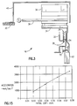
- these automatic operation systems have been powered by an electric motor which provides rotational torque, as shown in Fig. 1.
- a mechanical linkage system is there shown that converts the rotational force produced by the motor into a linear force required to move the door.
- Two common forms of mechanical linkages used include a two-bar linkage and a threaded lead screw.
- the concept being advanced by the present invention is to replace the combination of rotational motor and linkage with a linear electric motor.
- Linear electric motors have been suggested in the prior art for operating sliding doors and elevator doors.
- U.S. Pat. No. 3,462,883 shows a sliding door actuated by a linear inducting motor having a control circuit including a plurality of switches sequentially actuated by the door moving in either direction for effecting variable deceleration.
- Speed sensing is also used to modify the deceleration control.
- U.S. Pats. No. 4,067,144 and 4,090,113 disclose a method of driving a door of an automatic door assembly by a linear motor mounted within the automatic door assembly.
- the door is driven by a normal propulsion force which is augmented during a final portion of the stroke of the door, thereby overcoming the reaction force of cushioning devices provided near the ends of the door stroke.
- U.S. Pat. No. 3,872,622 discloses a linear motor for driving a pair of sliding doors, wherein the stator is fixed relative to the frame of the doors and its armature connected to a pulley and rope assembly, which is movable therewith to effect opening of the doors. Means are provided for adjusting the axis of rotation of the pulleys in three planes to adjust the tension on the rope and adjust the alignment of the pulleys.
- Linear motors are known for various types of doors, as shown, for example, in U.S. Pats. No. 5,134,324; 4,858,452; 4,188,552; 3,793,944; 4,365,442; and 3,708,915.
- the linear motor In addition to the desirable horizontal force, the linear motor also produces an attractive force between the primary and secondary of the motor. In previous art unrelated to door systems, for example, a linear motor for lifting an elevator in the hoistway, this force was opposed by rollers or bearings located on the primary parts, thus maintaining the air gap required between the secondary and primary components of the motor.
- An object of the present invention is to control an elevator door with a linear motor and at the same time minimize undesirable rotational torques.
- the present invention provides a method having the features according to claim 1.
- the present invention provides apparatus having the features according to claim 8.
- an elevator door is moved with a linear motor by providing a control signal that varies in magnitude with movement of the door, for counteracting a first rotational torque on the elevator door caused by a normal force exerted on the door acting through a variable-length moment arm about a center of gravity of the door and, in response to the control signal, varying the magnitude of a linear force exerted on the door acting through a fixed-length moment arm about the center of gravity of the door, for providing a second rotational torque opposing the first rotational torque, thereby counteracting the first rotational torque.
- the first and second rotational torques decrease with a decreasing length of the variable moment arm to zero at a point where the variable-length moment arm is zero, whereafter the first and second rotational torques increase with an increasing length of the variable-length moment arm until the door opening or closing operation is completed.
- the first and second rotational torques decrease and increase linearly with door position.
- a specific force and velocity profile may be used to provide torque counterbalance over the entire travel distance of the door.
- the horizontal velocity of the door varies in a curve approximating an ellipse on one side of its major axis.
- the normal force is used to levitate the door to reduce gravitational forces acting on horizontal door motion guide means.
- the normal force is held constant.
- the normal force is preferably selected in such a way as to achieve partial magnetic levitation of the door to reduce the gravity load on the door rollers and other suspension components, thus prolonging their life and reducing acoustic noise.
- one or more control signals are provided in response to a sensed door position signal.
- Control of the linear motor normal force may be achieved through digital techniques to provide a more perfect torque balance.
- the control may be implemented by sensing the door position and velocity and adjusting the motor drive frequency and slip to obtain the desired normal and linear force simultaneously.
- a specific force and velocity profile may be selected to provide torque counterbalance over the entire travel distance of the door.
- control signals may be provided in open-loop fashion in response to a door open or door close command signal.
- the motor includes a non-segmented secondary
- the present invention provides apparatus for moving an elevator door comprising a linear motor having a primary and a non-segmented secondary.
- Fig. 1 shows a prior art OVL operator wherein a rotational motion of the motor is translated into a linear motion by means of linkages.
- Fig. 2 shows a pair of elevator doors driven by linear motors, according to an embodiment of the present invention
- Fig. 3 shows a side view of a door motor mounting scheme, according to the embodiment of Fig. 2.
- Fig. 4 shows a control system, according to an embodiment of the present invention.
- Fig. 5 shows a linear motor powered elevator door system, according to an embodiment of the present invention.
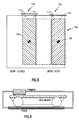
- Fig. 6 shows a linear motor schematic for showing that in addition to the linear or door propulsion force generated by the motor, a significant normal attraction force between the primary and secondary (approximately 0.5 to ten times the propulsion force) is generated, which can be used advantageously, according to preferred embodiments, for levitating the door to reduce gravitational forces acting on horizontal door movement guide means and for counterbalancing undesired torques.
- Fig. 7 illustrates door force components controlled, according to embodiments of the present invention.
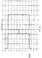
- Fig. 8 shows loads on the rollers shown as a function of time for a floating primary mount.
- Fig. 9 shows roller forces for a rigid primary mounting.
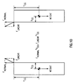
- Fig. 10 shows torque cancellation, according to preferred embodiments of the present invention.
- Fig. 11 shows the balancing of the torque due to the linear force with the torque due to the normal force, according to preferred embodiments of the present invention.
- Fig. 12 shows a force profile that varies linearly with door location, thus giving torque cancellation throughout the door travel, according to preferred embodiments of the present invention.
- Fig. 13 shows a velocity profile, according to preferred embodiments of the present invention.
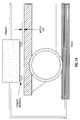
- Fig. 14 shows the linear motor schematic of Fig. 6 in more detail, showing a motor gap which is important for achieving a balanced acceleration.
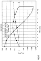
- Fig. 15 shows the relation between initial gap and acceleration required for torque counterbalance, for a scale model door test rig, according to an embodiment of the present invention.
- Fig. 16 shows theoretical door vertical position and rotation plotted against time for an embodiment, which shows that the door is actually lifted a small amount during the position traverse.
- Fig. 17 shows door motion, including acceleration, velocity and position plotted against time, according to the same embodiment.
- Fig. 18 shows linear motor forces, including normal magnetic force and linear force plotted against time, according to the same embodiment.
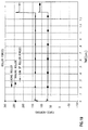
- Fig. 19 shows roller forces, including leading roller, trailing roller and the sum of roller forces plotted against time, illustrating that the leading and trailing roller forces are identical, thereby showing perfect torque cancellation, according to the same preferred embodiment.
- Fig. 2 shows a pair 10 of elevator doors 12, 14 in a closed position whereby, in one embodiment of the present invention, linear motor actuators 16, 18 are attached to both an overhead support 20 and the doors 12, 14 for opening and closing the doors 12, 14 in a reciprocating fashion similar to the opening and closing motion known from the device of Fig. 1.
- Fig. 3 shows a side view of the left door 12 attached to a door hanger 24, also shown in Fig. 2, which includes a roller 26 for rolling on a raised portion 28 of a door track 30 which may be shaped for rolling contact also with a second roller 32.
- the door track 30 may be attached to the support 20 of Fig. 2.
- the hanger 24 may also be used to support a reaction plate 34, sometimes called a secondary, of a linear motor including a separate primary 36 mounted on the support 20 by means, for example, of a mount 38.
- a dust cover 40 is also illustrated in both Figs. 2 and 3.
- the primary of the embodiment shown is mounted on the support 20, while the secondary is attached to the door and therefore moves with respect to the primary.
- the primary can take the form of a relatively small package of coils for being excited by one or more time-varying electric signals for generating time-varying electromagnetic fields that cause the secondary to move with respect to the primary.
- Such a linear motor is provided by Krauss Maffei, which also provides linear direct drives for controlling the motion of the linear motor.
- Such may be found in the product line of Krauss Maffei under the Series No. LIM-E Series Single-Cam Linear Motors. A brochure describing this series is available from a U.S. representative of Krauss Maffei AG, i.e., from Automation & Servo Technologies, Inc., at 1 Tunxis Road, Simsbury, Connecticut, USA.
- These drives and motors have known characteristics and can be adapted for the elevator application disclosed herein.
- the control system comprises a transistor pulse-controlled AC inverter which is responsive to control signals from a guidance system for providing, for example, three-phase power to the coils of the primary.
- the guidance system is responsive to set points and may also be part of a closed loop, for example, responsive to a sensed position signal having a magnitude indicative of the relative displacement of the primary along the secondary.
- a linear measuring system is provided by Xrauss Maffei that is suitable for such a linear measurement.
- Xrauss Maffei that is suitable for such a linear measurement.
- control system need not be closed-loop, but may be open-loop; similarly, it need not be implemented in a position-controlled loop, but may be implemented in a speed-regulated drive, a single-axis positioning drive, a position-regulated drive, a linear power actuator or any other desired configuration.
- FIG. 4 shows an advanced door system drive block diagram.
- a computer control system 50 is responsive to operational commands and some or all of a plurality of sensed signals, including a sensed position signal on a line 52, an obstacle detector signal on a line 54, a travel limit signal on a line 56, a reverse EMF sensed signal on a line 58 and a force/load sensed signal on a line 60, for providing a control signal on a line 62 to a motor control 64, which may also be responsive to the reverse EMF sensed signal on the line 58.
- the computer control system 50 may also provide status information on a line 66.
- the computer control system receives operational commands from other elevator or building systems or subsystems on the signal line 51 to initiate the various operational features of the door system (e.g., open, closed, stop, reverse, etc.). As mentioned, the computer control system 50 may also provide other systems with status information on the line 66 describing the state of the door system.
- the computer control system will accept inputs from the various sensors and, based on algorithms stored within, the computer control system will exercise such functions as generating the motion profiles for the door, calculating the motor drive phase and current, controlling the door position, velocity and acceleration (either through open-loop or closed-loop control), monitoring the performance of the door system, and any other functions deemed necessary to achieve the desired operational performance of the door system.
- the position sensor 52a signal on the line 52 will be fed into a comparator (not shown) where it will be compared with a position command signal, which may be a signal on the line 51 or which may be generated within the computer control system 50 itself (in which case it is not shown).
- the comparator will provide a difference signal which may be provided to a compensation network, such as a proportional control, a proportional-plus-integral control, a proportional-plus-integral-plus derivative control, or any other compensation network which may be desired.
- the compensation network will provide the control signal on the line 62.
- the motor control 64 may comprise circuits 68 that will generate the appropriate timing and phase relationships required to produce the desired forces (linear and/or normal) in the linear motor.
- Power drivers 70 will amplify signals on a line 72 from the phase and timing control logic to deliver the appropriate electrical power on a line 74 to the linear motor primary windings 76.
- the signal on the line 74 may be sensed by motor winding current sensors 78, which may be any type of current sensor desired.
- the motor winding current sensors 78 will provide sensed signals (not shown) back to the computer control system 50 for the purpose of closed-loop feedback, such as already described in connection with the position sensors 52a.
- the motor control 64 may operate either open-loop, based on predefined patterns, or may operate in a closed-loop manner, also based on such patterns but also using feedback from the optional motor winding current sensors and/or the optional door position sensors or any other desired sensor, such as a velocity-based feedback loop, or based on some other sensed parameter.
- the linear motor of Fig. 4 consists of two parts.
- the primary 76 consists of a number of poles around which the motor windings are placed.
- a secondary 80 consists of a structure which moves in a transverse linear direction relative to the primary in response to magnetic fields generated by the primary.
- the secondary provided by the above-cited vendor, i.e., Krauss-Maffei, is segmented to improve efficiency.
- a segmented secondary is one in which the electrical conductors are embedded in slots in the secondary backiron, a practice which is common for rotating induction motors.
- a solid secondary consisting of a magnetically permeable material (such as an iron or steel bar) covered with an electrically conductive layer, such as copper or aluminum sheet, which helps to reduce vibrations and hence door noise, which in certain applications is more important than efficiency.
- a permanent magnet secondary was considered but is not preferred due to the possibility of collecting metal particles in an elevator hoistway environment.
- sensors shown in Fig. 4 are optional and may be included in the electronic drive shown in Fig. 4 to provide any desired degree of control or other information to other parts of the drive system.
- typical sensors might include a feedback device 52a that measures the position of the door as it moves back and forth.
- Sensors 78 that measure the current flowing through the windings of the linear motor primary can also be used to both control and monitor the power drive to the primary.
- Travel limit sensors 56a, 56b may be used to sense discrete positions of door travel.
- Reverse EMF sensors 58a may be used to monitor the rate of motion of the linear motor.
- An obstacle detector 54a may be included in the door drive system to sense the presence of obstacles in the path of the door, allowing the computer control to select a control algorithm that avoids contact with the obstacle.
- Force and/or load sensors 60a, 60b may be included in the drive system to monitor both linear and normal forces and loads acting on the linear motor. All of these sensors are merely illustrative of useful devices that may be used in an actual implementation but need not be.
- Fig. 5 shows a center opening elevator door with two linear motors 100, 102 that are employed with each motor driving one side of a pair 104 of doors 106, 108.
- the door 106 is shown in the closed position, while the door 108 is shown in the open position.
- Each linear motor primary consists of a small (approximately 100 x 150 mm) electrically-active primary 110, 112, which is securely mounted to the car frame, such as the support 20 of Fig. 2, as shown further in Fig. 3.
- An electrically passive secondary 114, 116 or reaction plate (approximately 760 x 100 mm) is mounted to the movable door, as described previously in connections with Figs. 2 and 3.
- the configuration shown in Fig. 5 has the linear drive system mounted on top of the car, but such is not absolutely necessary to practice the invention.
- the invention can be used with a single moving door, as opposed to the pair 104 of moving doors shown in Fig. 5.
- the secondary or reaction plate 34 of that figure is simply an L-shaped extension to the existing car door hanger 24.
- the secondaries of Fig. 5 may be similar.
- Fig. 3 also shows a hinged (floating) mount for the primary, which has been described above.
- the top mounting that has been disclosed, as opposed in detail above to bottom mounting, was chosen to provide a relatively clean environment for the linear drive system.
- the cleanliness of the reaction plate is further improved by using the dust cover 40 of Fig. 3 over the entire assembly.
- the primary motor mounting scheme shown in Fig. 3 is a floating mount where the primary is free to move in the vertical plane but is restrained in the horizontal plane; such, however, is not the only approach.
- Another, better approach is a fixed mounting where the linear motor primary is restrained in both the horizontal and vertical planes. The advantages of the fixed mount will be explained subsequently.
- the linear motor in normal operation produces not only the desired linear propulsion force but also an attractive force between the primary and secondary elements of the motor, as shown in Figs. 6 and 7.
- the linear. motor primary may be centered above the left edge of the door.
- This attractive force is denoted by the term "normal force" herein.
- the normal force for linear motors depends on the exact design and electrical characteristics of the motor but, in general, may be characterized as being between 0.5 and 10 times the desired linear force produced. This force will tend to draw the primary and secondary elements of the linear motor together and must be controlled to maintain a consistent air gap between the two elements.
- the two primary mounting schemes described above use different schemes to control the air gap.
- the floating primary mounting accomplishes the air gap control using a set of rollers, such as shown in Fig. 6, mounted on the same mounting as the secondary element. Since the primary is free to move in the vertical plane, all the normal force loads are restrained through the rollers, and a consistent air gap is maintained. In this case, the normal force is not available to counterbalance torques on the door.
- This system using the vertically-floating primary, is self-adjusting in that the air gap is maintained by components of the primary and thus would not be affected by small changes in car/door geometry, such as those produces by temperature, stress and wear.
- the mounting scheme wherein the primary is rigidly mounted to the car frame uses the door weight and suspension system to resist the normal force and thus maintain a consistent air gap.
- This mounting method has the advantage of torque cancellation using the normal force, and is the preferred approach, according to the invention.
- FIG. 7 A force diagram of a typical elevator door 120 is shown in Fig. 7.
- a torque in the plane of the door is produced by the moment arm H cg shown in Fig. 7.
- this torque must be resisted by a difference in the loads on the two door suspension rollers 122,124, shown as forces F1 and F2.
- the normal force (F n ) generated by the motor is used to generate another torque opposing and thus reducing or eliminating the acceleration torque.
- FIGs. 8 and 9 A comparison of the suspension loads using a center-of-gravity, top-mounted, floating linear drive and top-mounted rigid linear drive is shown in Figs. 8 and 9.
- the test case for this data is a single door having a travel of 609 mm and accelerating at a rate of 1290 mm/sec2.
- a maximum door speed of 700 mm/sec is also utilized. This results in a profile accelerating for the first 0.62 seconds, a constant velocity region and then a deceleration beginning at time 0.8 seconds.
- the total door operating time is 1.4 seconds.
- the door weighs 68 kg.
- the torque produced by the linear drive must be resisted by the door rollers.
- Loads on the rollers are shown as a function of time in Fig. 8 and show a force of between +72 and -4 kg must be produced to prevent door rotation. Note that the torque requirements reverse when the direction of the acceleration is reversed. Note also that one of the rollers must produce a negative force during a large portion of the action time; a negative force implies that the roller force must push the door down.
- the force profile required using a rigid primary mounting is shown in Fig. 9.
- the assumption for this profile includes a ratio of normal-to-linear force of 5.0 and the primary portion of the linear motor located 304.6 mm from the center of gravity of the door at the initial position.
- the range of forces (F1) required from the leading edge roller is -25 to +15 kg, while the trailing roller (F2) requires -5 to -40 kg.
- F1 normal-to-linear force
- F2 the force profile required from the leading edge roller
- a force profile for driving the door that will result in a linear variation in torque produced by the force F LINEAR , that exactly counterbalances the torque produced by the force F NORMAL .
- This force profile specified is a linear variation of force with distance having a maximum magnitude at the end points of the travel range and being zero at the midpoint of the travel.
- the standard force profile normally used with power-operated doors is also shown in solid lines in Fig. 12.
- the normally used force profile is discontinuous, with the maximum force being applied over the first half of the travel range and the maximum negative force being applied over the final half of the travel range.
- Use of this force profile results in the triangular velocity profile shown in the solid line in Fig. 13.
- the sharp peak of this velocity profile contributed to noise and rough door motion in the prior art.
- the torque counterbalance force profile shown in dashed lines in Fig. 12 results in a velocity profile having a smooth peak, as shown in Fig. 13.
- the F LINEAR force driving the door produces a torque about the center of gravity of the door which varies linearly with door position due to the varying force F LINEAR , as described herein.
- the attractive force F NORMAL produces a torque in a sense opposite to that of F LINEAR and also varies linearly with door position due to the change in moment arm.
- This force distribution which opposes the torque may be generated by the following means:
- the force profile in the dashed line in Fig. 12 may vary linearly with door location, thus giving torque cancellation throughout the door travel, as shown in Fig. 11. It will be understood from Fig. 12 that, to maintain the same operation time as obtained in the prior art of Fig. 1, the peak force for the linear motor profile (dashed line) is somewhat greater than with the fixed force profile (solid line) of the prior art.
- the velocity profile (dashed line) using the linear force of Fig. 12 can be selected as shown to be much smoother than the solid profile shown using the prior art fixed-force profile of Fig. 12.
- the standard door roller tires compress approximately 0.25 mm under the normal door weight. If the door is lifted 0.10 mm, the load on the door rollers decreases to approximately 60 percent of the door weight.
- the normal force component of the linear motor provides the lifting force to balance the door and the level of normal forces controlled by the primary-secondary gap.
- the fraction of door weight on the door rollers is thus related to the desired door horizontal acceleration. We therefore have a partial magnetic suspension door due to the requirement for a torque-balancing normal force.
- the motor gap is shown in Fig. 14.
- balanced acceleration is a sensitive function of the initial gap, as shown in Fig. 15, where the gap for perfect torque cancellation as a function of acceleration is shown. This data was obtained from a sealed model of an elevator door system.
- Fig. 16 shows simulation results of vertical position and rotation of the door
- Fig. 17 shows door motion
- Fig. 18 shows linear motor forces described previously in connection with Fig. 10
- Fig. 19 shows roller forces described above.
- Fig. 18 shows the F NORMAL and F LINEAR forces associated with this particular case.
Landscapes
- Engineering & Computer Science (AREA)
- Automation & Control Theory (AREA)
- Physics & Mathematics (AREA)
- General Physics & Mathematics (AREA)
- Elevator Door Apparatuses (AREA)
- Power-Operated Mechanisms For Wings (AREA)
- Types And Forms Of Lifts (AREA)
- Linear Motors (AREA)
- Control Of Linear Motors (AREA)
Applications Claiming Priority (2)
| Application Number | Priority Date | Filing Date | Title |
|---|---|---|---|
| US29203 | 1993-03-10 | ||
| US08/029,203 US5373120A (en) | 1993-03-10 | 1993-03-10 | Linear door motor system for elevators |
Publications (2)
| Publication Number | Publication Date |
|---|---|
| EP0614844A2 true EP0614844A2 (de) | 1994-09-14 |
| EP0614844A3 EP0614844A3 (de) | 1995-01-25 |
Family
ID=21847776
Family Applications (1)
| Application Number | Title | Priority Date | Filing Date |
|---|---|---|---|
| EP94301697A Ceased EP0614844A3 (de) | 1993-03-10 | 1994-03-10 | Aufzugtürensystem mit Linearmotor. |
Country Status (8)
| Country | Link |
|---|---|
| US (1) | US5373120A (de) |
| EP (1) | EP0614844A3 (de) |
| JP (1) | JPH06321470A (de) |
| KR (1) | KR940021407A (de) |
| CN (1) | CN1101889A (de) |
| FI (1) | FI941123A7 (de) |
| RU (1) | RU2124469C1 (de) |
| SG (1) | SG48881A1 (de) |
Cited By (11)
| Publication number | Priority date | Publication date | Assignee | Title |
|---|---|---|---|---|
| EP0676525A1 (de) * | 1994-04-06 | 1995-10-11 | Otis Elevator Company | Linearinduktionsmotorantrieb für eine Aufzugstüre |
| EP0676527A1 (de) * | 1994-04-06 | 1995-10-11 | Otis Elevator Company | Linearer Induktionsmotor für den Türantrieb eines Aufzugs |
| EP0676526A1 (de) * | 1994-04-06 | 1995-10-11 | Otis Elevator Company | Aufrechterhaltung der Stromsteuerung mit offenen Regelkreis für einen Linearmotor |
| EP0676359A3 (de) * | 1994-04-08 | 1996-05-01 | Otis Elevator Co | Aufzugstürantriebsanordnung mit linearem Induktionsmotor. |
| EP0841293A1 (de) * | 1996-11-07 | 1998-05-13 | Otis Elevator Company | Optimierung des Magnetisierungsstroms in linearen Induktionsmotoren |
| EP0841285A1 (de) * | 1996-11-07 | 1998-05-13 | Otis Elevator Company | Aufzugskabinentürsystem |
| ES2120379A1 (es) * | 1995-09-25 | 1998-10-16 | Otis Elevator Co | Mecanismo de accionamiento triac para accionador de puerta de ascensor con motor de induccion lineal movido por linea trafasica. |
| US6832449B2 (en) | 2000-12-22 | 2004-12-21 | Inventio Ag | Door suspension system |
| EP1632634A3 (de) * | 2004-09-02 | 2010-02-17 | Vukv A.S. | Mit einem Linearmotor betätigte Tür für den öffentlichen Personennahverkehr, insbesondere Schienenfahrzeuge |
| EP1217160A3 (de) * | 2000-12-22 | 2010-04-14 | Inventio Ag | Türaufhängungssystem |
| ITUD20130106A1 (it) * | 2013-08-09 | 2015-02-10 | Mios Elettronica S R L | Apparecchiatura per l'apertura/chiusura di una porta per mezzi di trasporto e procedimento di apertura/chiusura di una porta |
Families Citing this family (35)
| Publication number | Priority date | Publication date | Assignee | Title |
|---|---|---|---|---|
| US5495918A (en) * | 1994-04-06 | 1996-03-05 | Otis Elevator Company | Smooth and quiet linear induction motor elevator door operation |
| US5668355A (en) * | 1994-04-07 | 1997-09-16 | Otis Elevator Company | Elevator cab door drive system |
| US5712546A (en) * | 1995-01-03 | 1998-01-27 | American Metal Door Company, Inc. | Control system for door positioning assembly |
| US5736693A (en) * | 1995-09-25 | 1998-04-07 | Otis Elevator Company | Elevator door drive using dual secondary linear induction motor |
| US5682023A (en) * | 1995-09-25 | 1997-10-28 | Otis Elevator Company | Time-optimal control of an AC line-driven linear motor elevator door operator |
| JPH09322518A (ja) * | 1996-05-28 | 1997-12-12 | Mitsubishi Electric Corp | 永久磁石使用同期形リニアモータ |
| US5756946A (en) * | 1996-11-07 | 1998-05-26 | Otis Elevator Company | Flexible mounting of a motor secondary in a linear induction motor for driving elevator car doors |
| US5862887A (en) * | 1996-11-07 | 1999-01-26 | Otis Elevator Company | High performance linear induction motor door operator |
| US5841082A (en) * | 1996-11-07 | 1998-11-24 | Otis Elevator Company | Secondary guidance system for linear induction motors driving elevator car doors |
| US6289643B1 (en) | 1999-09-07 | 2001-09-18 | Autoglide, Inc. | Residential motorized sliding door assembly |
| JP4527826B2 (ja) * | 2000-01-28 | 2010-08-18 | Thk株式会社 | 高推力リニアモータ及びその製造方法 |
| JP3972575B2 (ja) | 2000-11-02 | 2007-09-05 | 株式会社日立製作所 | ドアシステム |
| US6943508B2 (en) * | 2002-09-23 | 2005-09-13 | Otis Elevator Company | Tubular linear synchronous motor control for elevator doors |
| CA2502537C (en) * | 2005-03-30 | 2009-08-18 | Bahattin Gunes | Safety entrance norm (sen) |
| TW200722606A (en) * | 2005-07-14 | 2007-06-16 | Kaba Gilgen Ag | Sliding door construction for platforms and method for assembly thereof |
| US8132653B2 (en) * | 2005-07-21 | 2012-03-13 | Otis Elevator Company | Controlling elevator door orientation during door movement |
| ITTO20070396A1 (it) * | 2007-06-06 | 2008-12-07 | Oclap Srl | Barriera di accesso per banchine di stazioni ferroviarie |
| DE102007038844A1 (de) * | 2007-08-16 | 2009-02-19 | Dorma Gmbh + Co. Kg | Linearantrieb für Schiebetüren oder dergleichen |
| GB2467272B (en) * | 2007-11-01 | 2012-04-25 | Otis Elevator Co | Elevatoor door vibration and noise isolator |
| RU2422352C1 (ru) * | 2007-11-01 | 2011-06-27 | Отис Элевейтэ Кампэни | Устройство подвеса двери лифта, устройство двери лифта и кабина лифта |
| US20090260289A1 (en) * | 2008-04-18 | 2009-10-22 | Michael Carpenter | Door Safety System |
| US8729837B2 (en) * | 2009-09-04 | 2014-05-20 | Haas Automation, Inc. | Automatic door with position-dependent force limiting |
| KR101246512B1 (ko) * | 2009-09-10 | 2013-03-25 | 미쓰비시덴키 가부시키가이샤 | 엘리베이터 도어의 제어 장치 |
| EP2373573B1 (de) * | 2009-09-17 | 2015-01-28 | Dresser, Inc. | Flüssigkeitsspender mit mehrfachtür und methode |
| US8863908B2 (en) * | 2010-09-09 | 2014-10-21 | Inventio Ag | Controlling a drive motor of an elevator installation |
| ES2558355T3 (es) * | 2012-08-10 | 2016-02-03 | Wittur Holding Gmbh | Acoplador de puerta con descarga del elemento de bloqueo de puerta de caja |
| BR112015008724B1 (pt) * | 2012-10-30 | 2021-09-21 | Inventio Ag | Dispositivo para impedir uma velocidade excessiva de uma folha de porta, processo para operação de uma porta de elevador e porta de elevador |
| DE112013006825B4 (de) * | 2013-03-12 | 2020-02-13 | Mitsubishi Electric Corporation | Aufzugtür-Steuervorrichtung |
| US20160297648A1 (en) * | 2013-12-05 | 2016-10-13 | Otis Elevator Company | Stator reduction in ropeless elevator transfer station |
| CN114637375B (zh) | 2014-03-28 | 2025-01-28 | 英特尔公司 | 计算设备中磁力的调节 |
| CN108657893B (zh) * | 2018-05-28 | 2020-07-28 | 苏州汇川技术有限公司 | 一种电梯救援方法、系统以及控制器 |
| EP3825270B1 (de) * | 2019-11-22 | 2025-10-22 | KONE Corporation | Verfahren zum betrieb eines aufzugs und und ein aufzug |
| US20210403277A1 (en) * | 2020-06-25 | 2021-12-30 | Tk Elevator Innovation And Operations Gmbh | Systems and methods for auto-tuning elevator controllers |
| FR3135050B1 (fr) * | 2022-05-02 | 2024-03-15 | Faiveley Transp Tours | Porte d’accès à un véhicule de transport comprenant des moyens pour diagnostiquer une détection correcte de la présence de passagers, véhicule et procédé de mise en œuvre correspondants |
| CN115947212B (zh) * | 2022-12-02 | 2026-02-24 | 苏州汇川控制技术有限公司 | 电梯轿门控制方法、装置、终端设备及介质 |
Family Cites Families (23)
| Publication number | Priority date | Publication date | Assignee | Title |
|---|---|---|---|---|
| GB1065562A (en) * | 1965-01-14 | 1967-04-19 | Morris Ltd Herbert | Improvements in mean for automatically operating and controlling reciprocating motion |
| US3440532A (en) * | 1965-05-07 | 1969-04-22 | Skinner Precision Ind Inc | Speed sensor for linear induction motors |
| GB1274341A (en) * | 1970-02-06 | 1972-05-17 | Morris Ltd Herbert | Improvements in apparatus for operating swing doors |
| DE2210828A1 (de) * | 1972-03-07 | 1973-09-13 | Eaton Gmbh | Automatischer antrieb fuer schiebetueren |
| US3793944A (en) * | 1972-07-05 | 1974-02-26 | J Potter | Coin operated refuse compactor system |
| DE2255780A1 (de) * | 1972-11-14 | 1974-05-16 | Siemens Ag | Antrieb fuer schiebetueren |
| NL7315725A (de) * | 1972-12-30 | 1974-07-02 | ||
| JPS51138040A (en) * | 1975-05-24 | 1976-11-29 | Yoshida Kogyo Kk <Ykk> | Door body driving method for an automatic door |
| JPS5814551B2 (ja) * | 1975-06-10 | 1983-03-19 | ワイケイケイ株式会社 | ジドウトビラノヒタイクドウホウホウ |
| US4188552A (en) * | 1977-10-26 | 1980-02-12 | Linear International Corporation | Garage door opener including a linear actuator |
| US4365442A (en) * | 1979-07-17 | 1982-12-28 | Speer Harold A | Automatic door control system |
| US4305481A (en) * | 1979-12-27 | 1981-12-15 | Otis Elevator Company | Elevator door motion modification |
| SU1177255A1 (ru) * | 1983-12-29 | 1985-09-07 | Ордена Октябрьской Революции Карачаровский Механический Завод | Привод раздвижной двери кабины лифта |
| JPS614455A (ja) * | 1984-06-14 | 1986-01-10 | Canon Inc | リニアモ−タ |
| DE3663376D1 (de) * | 1985-03-20 | 1989-06-22 | Shinko Electric Co Ltd | Door apparatus |
| US4858452A (en) * | 1986-12-22 | 1989-08-22 | United Technologies Electro Systems, Inc. | Non-commutated linear motor |
| JPH01259705A (ja) * | 1988-04-05 | 1989-10-17 | Toshiba Corp | リアクションプレート |
| JPH0745745Y2 (ja) * | 1989-12-19 | 1995-10-18 | トヨタ車体株式会社 | 自動ドア用磁石可動型リニアモータ |
| JP2504257B2 (ja) * | 1990-02-16 | 1996-06-05 | 三菱電機株式会社 | エレベ―タ―のドア制御装置 |
| JPH03244777A (ja) * | 1990-02-21 | 1991-10-31 | Okamura Corp | 磁気浮上自走式懸垂引き戸 |
| JPH03264486A (ja) * | 1990-03-12 | 1991-11-25 | Mitsubishi Electric Corp | エレベータのかごドア装置 |
| JP2881622B2 (ja) * | 1990-04-24 | 1999-04-12 | 株式会社岡村製作所 | 磁気浮上式引き戸の開閉装置 |
| JPH0745746Y2 (ja) * | 1990-11-07 | 1995-10-18 | 川崎重工業株式会社 | 扉類等の駆動装置 |
-
1993
- 1993-03-10 US US08/029,203 patent/US5373120A/en not_active Expired - Fee Related
-
1994
- 1994-03-09 FI FI941123A patent/FI941123A7/fi unknown
- 1994-03-10 JP JP6040189A patent/JPH06321470A/ja not_active Withdrawn
- 1994-03-10 EP EP94301697A patent/EP0614844A3/de not_active Ceased
- 1994-03-10 KR KR1019940004686A patent/KR940021407A/ko not_active Withdrawn
- 1994-03-10 RU RU94007643A patent/RU2124469C1/ru active
- 1994-03-10 CN CN94104257A patent/CN1101889A/zh active Pending
- 1994-03-10 SG SG1996003343A patent/SG48881A1/en unknown
Cited By (15)
| Publication number | Priority date | Publication date | Assignee | Title |
|---|---|---|---|---|
| EP0676525A1 (de) * | 1994-04-06 | 1995-10-11 | Otis Elevator Company | Linearinduktionsmotorantrieb für eine Aufzugstüre |
| EP0676527A1 (de) * | 1994-04-06 | 1995-10-11 | Otis Elevator Company | Linearer Induktionsmotor für den Türantrieb eines Aufzugs |
| EP0676526A1 (de) * | 1994-04-06 | 1995-10-11 | Otis Elevator Company | Aufrechterhaltung der Stromsteuerung mit offenen Regelkreis für einen Linearmotor |
| US5503248A (en) * | 1994-04-06 | 1996-04-02 | Otis Elevator Company | Maintaining open loop current drive to linear induction motor |
| US5509504A (en) * | 1994-04-06 | 1996-04-23 | Otis Elevator Company | Velocity regulated, open current loop, variable voltage, variable frequency, linear induction motor drive for an elevator car door |
| US5612518A (en) * | 1994-04-08 | 1997-03-18 | Otis Elevator Company | Linear induction motor door drive assembly for elevators |
| EP0676359A3 (de) * | 1994-04-08 | 1996-05-01 | Otis Elevator Co | Aufzugstürantriebsanordnung mit linearem Induktionsmotor. |
| ES2120379A1 (es) * | 1995-09-25 | 1998-10-16 | Otis Elevator Co | Mecanismo de accionamiento triac para accionador de puerta de ascensor con motor de induccion lineal movido por linea trafasica. |
| EP0841293A1 (de) * | 1996-11-07 | 1998-05-13 | Otis Elevator Company | Optimierung des Magnetisierungsstroms in linearen Induktionsmotoren |
| EP0841285A1 (de) * | 1996-11-07 | 1998-05-13 | Otis Elevator Company | Aufzugskabinentürsystem |
| US5896951A (en) * | 1996-11-07 | 1999-04-27 | Otis Elevator Company | Optimization of magnetizing current in linear induction motors |
| US6832449B2 (en) | 2000-12-22 | 2004-12-21 | Inventio Ag | Door suspension system |
| EP1217160A3 (de) * | 2000-12-22 | 2010-04-14 | Inventio Ag | Türaufhängungssystem |
| EP1632634A3 (de) * | 2004-09-02 | 2010-02-17 | Vukv A.S. | Mit einem Linearmotor betätigte Tür für den öffentlichen Personennahverkehr, insbesondere Schienenfahrzeuge |
| ITUD20130106A1 (it) * | 2013-08-09 | 2015-02-10 | Mios Elettronica S R L | Apparecchiatura per l'apertura/chiusura di una porta per mezzi di trasporto e procedimento di apertura/chiusura di una porta |
Also Published As
| Publication number | Publication date |
|---|---|
| SG48881A1 (en) | 1998-05-18 |
| EP0614844A3 (de) | 1995-01-25 |
| RU94007643A (ru) | 1996-08-27 |
| FI941123A0 (fi) | 1994-03-09 |
| FI941123A7 (fi) | 1994-09-11 |
| RU2124469C1 (ru) | 1999-01-10 |
| US5373120A (en) | 1994-12-13 |
| KR940021407A (ko) | 1994-10-17 |
| JPH06321470A (ja) | 1994-11-22 |
| CN1101889A (zh) | 1995-04-26 |
Similar Documents
| Publication | Publication Date | Title |
|---|---|---|
| US5373120A (en) | Linear door motor system for elevators | |
| CA2181882C (en) | Method and equipment for the measurement of the load in a lift cage | |
| EP0641735B1 (de) | Horizontales Aufzugsaufhängungssystem mit Regelvorrichtung | |
| CN111170101B (zh) | 监视系统 | |
| GB2268289A (en) | Reducing cage vibration due unbalance in a lift | |
| JP3639606B2 (ja) | エレベータの乗り心地を改善する方法及び装置 | |
| JPWO2011027450A1 (ja) | エレベーターのドア装置 | |
| EP0982643B1 (de) | Automatische Einstellung der offenen Schleifenverstärkung eines magnetischen Aktuators für die aktive Aufhängung eines Aufzuges | |
| CZ58397A3 (en) | Process and apparatus for adjusting equalizing time of elevator cage | |
| JP2865949B2 (ja) | エレベータの制振装置 | |
| EP0807084B1 (de) | Steuerungsverfahren und -vorrichtung für aufzughebemotor | |
| RU2103219C1 (ru) | Узел кабины лифта (варианты) | |
| US5542501A (en) | Apparatus for controlling an elevator to reduce vibrations created in a linear drive motor | |
| JP2000219441A (ja) | 制振装置 | |
| CN1053160C (zh) | 起动电梯的方法 | |
| US5838126A (en) | Method and apparatus for opening or closing a door by measuring the instantaneous voltage and current in an associated motor | |
| US5367132A (en) | Centering control for elevator horizontal suspension | |
| US7537091B2 (en) | Magnetic elevator door mover | |
| JP4231848B2 (ja) | モータ駆動制御装置 | |
| JPH07196273A (ja) | エレベーターの姿勢制御装置 | |
| JPH04148785A (ja) | エレベータ駆動装置 | |
| EP3587327B1 (de) | Elektromagnetische führung für elektronischen sicherheitsauslöser | |
| JPH03221687A (ja) | 扉開閉用リニアモータ | |
| EP3696130B1 (de) | Aufzugseingang mit magnetischer führung zur steuerung der bewegung der türblätter | |
| EP0751089A2 (de) | Türsystem mit Linearmotor für Aufzüge |
Legal Events
| Date | Code | Title | Description |
|---|---|---|---|
| PUAI | Public reference made under article 153(3) epc to a published international application that has entered the european phase |
Free format text: ORIGINAL CODE: 0009012 |
|
| AK | Designated contracting states |
Kind code of ref document: A2 Designated state(s): CH DE ES FR GB IT LI |
|
| PUAL | Search report despatched |
Free format text: ORIGINAL CODE: 0009013 |
|
| AK | Designated contracting states |
Kind code of ref document: A3 Designated state(s): CH DE ES FR GB IT LI |
|
| 17P | Request for examination filed |
Effective date: 19950408 |
|
| 17Q | First examination report despatched |
Effective date: 19970515 |
|
| GRAG | Despatch of communication of intention to grant |
Free format text: ORIGINAL CODE: EPIDOS AGRA |
|
| STAA | Information on the status of an ep patent application or granted ep patent |
Free format text: STATUS: THE APPLICATION HAS BEEN REFUSED |
|
| 18R | Application refused |
Effective date: 19981123 |