EP0616103B1 - Dispositif antivol de sécurité - Google Patents
Dispositif antivol de sécurité Download PDFInfo
- Publication number
- EP0616103B1 EP0616103B1 EP93115363A EP93115363A EP0616103B1 EP 0616103 B1 EP0616103 B1 EP 0616103B1 EP 93115363 A EP93115363 A EP 93115363A EP 93115363 A EP93115363 A EP 93115363A EP 0616103 B1 EP0616103 B1 EP 0616103B1
- Authority
- EP
- European Patent Office
- Prior art keywords
- locking
- slide
- jacket
- tongues
- wall
- Prior art date
- Legal status (The legal status is an assumption and is not a legal conclusion. Google has not performed a legal analysis and makes no representation as to the accuracy of the status listed.)
- Expired - Lifetime
Links
Images




Classifications
-
- E—FIXED CONSTRUCTIONS
- E05—LOCKS; KEYS; WINDOW OR DOOR FITTINGS; SAFES
- E05B—LOCKS; ACCESSORIES THEREFOR; HANDCUFFS
- E05B73/00—Devices for locking portable objects against unauthorised removal; Miscellaneous locking devices
- E05B73/0017—Anti-theft devices, e.g. tags or monitors, fixed to articles, e.g. clothes, and to be removed at the check-out of shops
- E05B73/0023—Containers, boxes, cases or the like, e.g. for compact discs or video-cassettes, specially adapted therefor
Definitions
- the present invention relates to an anti-theft device for flat objects, especially video or Music tapes and the like, with one for recording Object specific container, consisting of the lower part of the container and hinged lid or a case with one Narrow-side insertion opening and one towards the securing object attachable, together with the object slider that can be inserted into the casing, and with locking means between the lower part of the container and the lid or between Cover and slide, and with the container or on the Cover arranged signal transmitter for triggering an alarm, in each case according to the preamble of claim 1 or 9.
- the container is made or the shell usually made of hard plastic, which a box-shaped object to be secured against theft has to record, such as a CD cassette, the envelope with a so-called resonant circuit label is provided so that when passing one at the exit of sales shops arranged induction loop an alarm is triggered when the envelope including the object is taken without payment.
- a box-shaped object to be secured against theft has to record, such as a CD cassette
- the envelope with a so-called resonant circuit label is provided so that when passing one at the exit of sales shops arranged induction loop an alarm is triggered when the envelope including the object is taken without payment.
- a special tool As a rule, at the Checkout of a retail store's reusable case separated from the CD cassette using a special tool.
- a wide variety of locking systems are known using bolts, pins or hooks for this, which connect the shell with the object until unlocking is carried out using a special tool.
- a particularly suitable embodiment of such a device according to the preamble of claim 1 is known from EP-A-0 508 201 of the applicant, which is characterized in that on one of two each other opposite narrow sides of the shell on the inside a longitudinally displaceable bow-shaped auxiliary element is provided, at the ends of which protrudes at right angles stiff leg is provided, the box-shaped Object between these legs when moving is caught and the outer temple end piece resilient is bendable to the object when the bracket is extended to be removed from the sheath and thus from the sheath, while the inside temple end next to the protruding Leg one, seen in the longitudinal direction of the temple, outside the Thigh lying, also protruding locking lug has, which is intended at substantially bracket fully inserted into the case into one Locking slot on the opposite of the insertion opening Snap the narrow side of the case into place, with a desired one Unlocking takes place using a special tool.
- EP-A-0 483 422 is for a receptacle with articulated Cover known another solution according to the preamble of claim 9, which for theft protection has a simple spring-loaded latch, which in turn is in a sliding closure element is arranged and can only be released by means of a magnet.
- a bolt that can be easily detached by means of a magnet can not meet today's security requirements.
- the essence of the invention thus lies in the interaction of deflectable tongues arranged latches with recesses in the sliding latch or in the side Boundary wall of the slide.
- a particularly preferred embodiment of the subject matter of the invention is characterized by the fact that the locking strap several, preferably three arranged one behind the other has resilient tongues with latches and that in the bolt or in the boundary wall of the slide one of the number of Tongues corresponding number of recesses for receiving the Latches is provided.
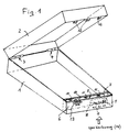
- FIG. 1 of the drawing shows purely schematically a fuse box, consisting of lower part 1 and hinges 3, 4 hinged lid 2.
- a locking mechanism consisting of a locking band 8 made of resilient Material (e.g. steel or brass), in the level of three resilient Tongues 9 are provided, which are in the locked position stick to one side with the catches attached and in recesses of a displaceable bolt 10 intervention.
- FIG. 2 and 3 show enlarged sections of the locking mechanism in the open position (Fig. 2) or locking position (Fig. 3).
- the firmly anchored locking band 8 has three tongues 9, which in the open position against the Slidable latch 10 abut.
- the latter is three Provided recesses 10 'into which the latches 9' Snap tongues 9 into the locked position (see Fig. 3).
- the latches 9 ' have an extension 9 ", which when pushing back under the edge of the recesses 10 ' can, so that no unintentional opening can take place.
- FIG. 4 An embodiment of the slide 10 with recesses 10 'and Noses 11 and slider button 13 is in Fig. 4 (view from shown above and top view).
- Fig. 5 shows a stamped part for forming the locking band 8th.
- the free ends 9 "'of the tongues 9 are slightly angled and are in the locked position in space 5, such that it is gripped by means of a special tool 14 and thus the latches are pulled out of the locked position can be.
- the bolt 10 can then be in the open position again are pushed back (Fig. 2).
- the tongues 9 could also by means of magnetic force be lifted out of the locked position, with the Increasing security, in particular a solution according to FIG. 20 pushes: At the tip of three tongues 9 are magnetic pieces different polarity attached, which thus only lifted out of the locked position at the same time can be, if also unlocking magnets different Polarity can be used.
- Fig. 6 of the drawing shows a purely schematic of an anti-theft device according to the invention. It basically exists from a sleeve 100 made of plastic, which in turn is from a lower and upper shell half 102 and 103 is composed, which is composed in a manner known per se will.
- the envelope 100 has a narrow side Insertion opening 101 'for the object 105 to be secured, e.g. a music cassette, on.
- the envelope 100 can on the Top side have a large recess 101 ", which view granted on the content.
- the envelope is in a manner known per se with an alarm transmitter equipped, e.g. an oscillating circuit label so that it passes one arranged at the exit of sales shops Induction loop triggers an alarm when the envelope including the item taken away without payment (when paying, the case is removed from the object using a special tool solved).
- an alarm transmitter equipped, e.g. an oscillating circuit label so that it passes one arranged at the exit of sales shops Induction loop triggers an alarm when the envelope including the item taken away without payment (when paying, the case is removed from the object using a special tool solved).
- the actual locking of the object 105 with the Envelope 100 is made by means of a slide 104, which is the object at least partially included and only when pulled out Object can be solved by this.
- the object 105 can also be partially removed from the envelope 100 pulled slide 104 removed from this or in this be inserted.
- FIG. 7 shows an illustration of the device according to FIG. 6 removed shell top 103, namely the lower shell half 102, the slide 104, which is to be secured Item 105 clasped, and, the most important element, a Locking strap 106, which in the directly adjacent Narrow side inner wall 102 'of the sheath 100 or 102 cannot be moved is arranged.
- the locking band 106 runs parallel to the casing wall and practically lies against it.
- the Band 106 is made of resilient material, e.g. made of brass or spring steel, and has three evenly spaced resilient tongues 107 arranged one behind the other. Each Tongue 107 has two parallel latches 107 'and one free tongue end 107 ".
- the latches 107 ' are in the normal or locked position to the inside of the case from the level of the locking band 106 in front, while the free tongue ends 107 " protrude from the band level at a slight angle to the casing wall and recorded by recesses in the shell wall will.
- Unlocking is extremely easy: by close to the edge Slots 108 in a cover side of the sheath can be a special tool (see Fig. 17 and 18) just inserted and then light be moved laterally until the tool is under the free Spring ends engages and the spring ends in over slopes In the direction of the shell wall, the latches automatically 107 'are brought out of engagement with the slide 104. The unlocked position is reached and the object 105 can be pulled out of the case together with the slider will.
- sleeve 100 and slide 104 can always be used reuse again by moving the slider to a new item and put the whole thing in the case to lock again is pushed in.
- the free ends of the resilient tongues 107 and optionally the latches can be hardened or made of hard metal if required exist to increase their lifespan.
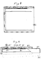
- Fig. 8 shows in detail a top view of a lower shell half 102. This case was made for the sake of better Overview neither the locking strap nor the slider inserted.
- Fig. 9 shows a plan view of the locking edge, with Envelope 102, slide 104 (with object to be secured 105) and Locking strap 106 with the resilient tongues 107 with their free ends 107 "and latches 107 ', the latter in Recesses snapped into the longitudinal wall of the slide 104 are.
- Tongue 107 shown in the unlocked state, i.e. with the free tongue end 107 "in a recess 102" of the case side wall swung out (using a special tool) and thus out the pawl 104 notched ratchet pawl 107 '.
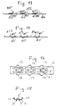
- FIG. 10 to 12 show the slide 104 with the wall parts 104 ', 104 ", 104"' and 104 '' '' for grasping an object and the recesses 109-111 for receiving the latches the locking band (not shown here).
- Fig. 12 shows a punch cut to form the slide 104.
- FIGS. 14 and 15 show the locking band 106.
- Fig. 13 shows ends 107 "raised by means of special tool 112 resilient tongues 107 and detent pawls 107 ', while FIGS. 14 and 15 the belt in the normal or locking position show, i.e. with free tongue ends 107 " one and latches 107 'on the other side of the belt level.
- the flanges 113 serve to fasten the band on the narrow inner wall of the case.
- FIGS. 17 and 18 illustrate a special tool in the form of a plate 114 with L-shaped fingers 115, which are provided with the bevelled parts 112 to reach under the free ends of the tongues 107 and in Bring unlocking position.
- the fingers 115 of the tool pass through recesses 108 in the case in the starting position of the unlocking, which is accomplished by a transverse shift. Doing so all tongues raised and in the unlocked position at the same time to be brought.
- the tool is usually in a table at the checkout arranged with fingers protruding upwards, so that only to put the cover over the fingers from above and with one translational movement to unlock.
- Fig. 19 shows how the tongues are split in the longitudinal center so that two adjacent tongue parts 207, 307 are available. An unauthorized lifting of the latches will thereby made considerably more difficult. This can also be done through additional structural measures (partitions, stops) will.
- the magnets of the tool can consist of electromagnets.
Landscapes
- Engineering & Computer Science (AREA)
- Multimedia (AREA)
- Burglar Alarm Systems (AREA)
- Air Bags (AREA)
- Package Frames And Binding Bands (AREA)
Claims (11)
- Dispositif antivol pour des objets plats, notamment des cassettes vidéo ou de musique et analogue, constitué d'une enveloppe (100) prévue pour recevoir l'objet avec une ouverture d'insertion (101') prévue sur un côté étroit et un transmetteur de signaux disposé d'une manière sûre à l'enveloppe pour déclencher une alarme, en outre d'un coulisseau (104) pouvant être placé sur l'objet à assurer et tenant celui-ci qui peut être inséré conjointement avec l'objet de manière déplaçable longitudinalement dans l'enveloppe (100) et enfin de moyens de verrouillage qui sont actifs entre une paroi intérieure (102') de côté étroit menant vers l'ouverture d'insertion (101') de l'enveloppe (100) et le coulisseau (104) et qui empêchent qu'un objet (105) inséré avec le coulisseau (104) placé sur celui-ci dans l'enveloppe (100) puisse être séparé de l'enveloppe sans utilisation d'un outil spécial, caractérisé en ce que les moyens de verrouillage présentent les éléments suivants :une bande de verrouillage (106) en un matériau d'une élasticité de ressort, disposée fixement dans la paroi intérieure de côté étroit (102') de l'enveloppe (100) opposée directement au coulisseau (104), s'étendant parallèlement à la paroi, dans le plan de laquelle est prévue au moins une languette élastique (107) pouvant être écartée vers les deux côtés de celui-ci, à partir de laquelle, en position normale, c'est-à-dire de verrouillage, fait saillie vers un côté, c'est-à-dire vers le côté intérieur de l'enveloppe, au moins un cliquet d'enclenchement (107') tandis que l'extrémité de languette libre (107") fait saillie suivant un léger coudage vers l'autre côté, c'est-à-dire vers la paroi extérieure de l'enveloppe pour être saisie, en vue du déverrouillage, par un outil spécial (114) et pour tirer ainsi le cliquet d'enclenchement (107') vers l'autre côté de la bande, c'est-à-dire de la position de verrouillage ;au moins un évidement dans la paroi intérieure de coté étroit précitée (102') de l'enveloppe (100) qui, dans la position de verrouillage, permet un pivotement de l'extrémité libre (107") de la languette (107) respectivement des languettes élastiques précitées de la bande de verrouillage (106) ;au moins un évidement (104") dans une paroi de délimitation (104') du coulisseau (104) orientée vers la bande de verrouillage (106) respectivement la paroi intérieure de côté étroit (102') de l'enveloppe, dans lequel s'enclenche le cliquet (107') respectivement les cliquets d'enclenchement de la bande (106) après un passage sur celle-ci et empêche le retrait du coulisseau (104) respectivement de l'objet à assurer ; etdes ouvertures (108) prévues dans la paroi extérieure de l'enveloppe ainsi qu'un outil spécial (114) pour l'insertion dans ces ouvertures, pour que l'outil s'engage sous la languette élastique (107) respectivement les languettes de la bande de verrouillage (106) pour tirer le cliquet d'enclenchement (107'), en vue du déverrouillage, de l'évidement (104'') du coulisseau (104) et pour déverrouiller le coulisseau (104) conjointement avec l'objet à assurer.
- Dispositif selon la revendication 1, caractérisé en ce que le cliquet d'enclenchement (107') présente un ergot d'extrémité faisant saillie vers l'arrière qui peut passer sous le bord de l'évidement (104'') après l'enclenchement.
- Dispositif selon l'une des revendications 1 à 2, caractérisé en ce que la bande de verrouillage (106) présente plusieurs, de préférence trois, languettes élastiques (107) disposées les unes derrière les autres avec des cliquets d'enclenchement (107') et qu'il est prévu dans le verrou respectivement dans la paroi de délimitation précitée du coulisseau (104) un nombre d'évidements (109-111) correspondant au nombre de languettes (107) pour recevoir les cliquets d'enclenchement (107').
- Dispositif selon l'une des revendications 1 à 3, caractérisé en ce que l'outil spécial (114) a la forme d'une plaque rigide avec un nombre de doigts de déverrouillage (115) en forme de L correspondant au nombre des languettes élastiques (107), les derniers pouvant être insérés à travers des ouvertures dans une partie de récipient ou dans la paroi de l'enveloppe et pouvant être poussés sous les extrémités libres des languettes pour relever celles-ci et pour sortir ainsi les cliquets d'enclenchement (107') de prise avec le verrou respectivement le coulisseau (104).
- Dispositif selon l'une des revendications 1 à 4, caractérisé en ce que chacune des languettes élastiques (107) présente deux cliquets d'enclenchement parallèles (107').
- Dispositif selon l'une des revendications 1 à 5, caractérisé en ce que plusieurs languettes élastiques (107) sont prévues à des écarts réguliers ou irréguliers les unes derrière les autres et en ce que les évidements (109-111) dans le verrou respectivement le coulisseau (104) sont disposés selon des écarts correspondants.
- Dispositif selon l'une des revendications 1 à 6, caractérisé en ce que chacune des languettes élastiques (107) est fendue le long de son milieu longitudinal.
- Dispositif selon l'une des revendications 1 à 6, caractérisé en ce que la bande de verrouillage (106) est réalisée en métal, notamment en laiton ou en acier de ressort.
- Dispositif antivol pour des objets plats, notamment des cassettes vidéo ou de musique, avec un récipient (1, 2) prévu pour recevoir l'objet, constitué d'une partie inférieure de récipient (1) et d'un couvercle articulé (2), et avec des moyens de verrouillage entre la partie inférieure du récipient et le couvercle et avec un transmetteur de signaux disposé au récipient pour déclencher une alarme, caractérisé en ce que les moyens de verrouillage présentent une bande de verrouillage (8) disposée fixement à la paroi intérieure d'un côté étroit de récipient, s'étendant parallèlement à la paroi, en un matériau ayant une élasticité de ressort dans le plan duquel est prévue au moins une languette élastique (9) pouvant être déviée de celui-ci vers les deux côtés, à partir de laquelle fait saillie vers un côté au moins un cliquet d'enclenchement (9') tandis que vers l'autre côté, l'extrémité libre de languette (9''') présente des moyens pour que, en vue du déverrouillage, le cliquet d'enclenchement (9') puisse être tiré en direction de l'autre côté de la bande par un outil spécial faisant partie du dispositif antivol de la position de verrouillage, la paroi intérieure du récipient étant configurée de façon à permettre dans la position de verrouillage un pivotement de l'extrémité libre (9"') de la languette respectivement des languettes (9) de la bande de verrouillage (8), en ce qu'il est prévu en outre un verrou (10) guidé de manière déplaçable le long de la bande de verrouillage (8), s'appliquant à la bande (8), avec au moins un évidement (10'), et dans ce dernier s'enclenchent les cliquets d'enclenchement (9') de la bande (8) lors d'un passage sur celle-ci et le verrou (10) s'engage dans cette position sous des ergots de retenue à l'autre partie de récipient de façon à empêcher une ouverture du récipient dans la position de verrouillage sans utilisation de l'outil spécial, l'ensemble étant réalisé de façon que par l'utilisation d'un outil spécial (14), le cliquet d'enclenchement respectivement les cliquets d'enclenchement (9'), en vue du déverrouillage, peuvent être retirés de l'évidement respectivement des évidements (10') du verrou déplaçable (10).
- Dispositif selon la revendication 9, caractérisé en ce que les extrémités (9"') des cliquets d'enclenchement (9') peuvent être relevées de la position de verrouillage par des champs magnétiques appliqués à l'extérieur du récipient respectivement de l'enveloppe.
- Dispositif selon la revendication 10, avec au moins trois languettes de verrouillage (9), caractérisé en ce qu'au moins l'une des languettes (9), comparée aux autres languettes, présente une polarité magnétique inversée de telle sorte que pour le déverrouillage, des aimants d'une polarité différente correspondante doivent être utilisés.
Priority Applications (1)
| Application Number | Priority Date | Filing Date | Title |
|---|---|---|---|
| JP3211094A JPH06323052A (ja) | 1993-03-17 | 1994-03-02 | 盗難防止装置 |
Applications Claiming Priority (2)
| Application Number | Priority Date | Filing Date | Title |
|---|---|---|---|
| CH810/93 | 1993-03-17 | ||
| CH81093 | 1993-03-17 |
Publications (2)
| Publication Number | Publication Date |
|---|---|
| EP0616103A1 EP0616103A1 (fr) | 1994-09-21 |
| EP0616103B1 true EP0616103B1 (fr) | 1998-05-27 |
Family
ID=4195707
Family Applications (1)
| Application Number | Title | Priority Date | Filing Date |
|---|---|---|---|
| EP93115363A Expired - Lifetime EP0616103B1 (fr) | 1993-03-17 | 1993-09-23 | Dispositif antivol de sécurité |
Country Status (4)
| Country | Link |
|---|---|
| EP (1) | EP0616103B1 (fr) |
| AT (1) | ATE166691T1 (fr) |
| DE (1) | DE59308611D1 (fr) |
| ES (1) | ES2116379T3 (fr) |
Cited By (7)
| Publication number | Priority date | Publication date | Assignee | Title |
|---|---|---|---|---|
| US6598742B1 (en) | 1998-01-29 | 2003-07-29 | Nexpak Corporation | Lockable media storage box with lock and key |
| US7140489B2 (en) | 2003-03-26 | 2006-11-28 | Autronic Plastics, Inc. | Denial system for securing an asset within a container and methods of use |
| USD544743S1 (en) | 2005-09-26 | 2007-06-19 | Autronic Plastics, Inc. | Media storage case |
| US7257971B2 (en) | 2000-07-31 | 2007-08-21 | Autronics Plastics Inc. | Case with internal lock |
| US7451627B2 (en) | 2003-08-28 | 2008-11-18 | Mw Security Ab | Lockable security device |
| US7552822B2 (en) | 1998-01-29 | 2009-06-30 | Nexpak Corporation | Lockable media storage box with lock and key |
| US8054194B2 (en) | 2003-02-10 | 2011-11-08 | Autronic Plastics, Inc. | System and method for verifying a security status of a lockable container |
Families Citing this family (23)
| Publication number | Priority date | Publication date | Assignee | Title |
|---|---|---|---|---|
| IT1298682B1 (it) * | 1997-02-14 | 2000-01-12 | Pietro Necchi | Custodia antifurto a ingombro ridotto, in particolare per compact disk, musicassette, videocassette e simili |
| US5904246A (en) * | 1997-02-19 | 1999-05-18 | Alpha Enterprises, Inc. | Magnetic locking mechanism for a security package |
| CA2320964C (fr) * | 1998-01-29 | 2007-04-17 | Necchi S.R.L. | Boitier antivol pour disques compacts, cassettes video, cassettes audio et analogues |
| US6474470B2 (en) | 1998-01-29 | 2002-11-05 | Nexpak Corporation | Lockable media storage box with lock and key |
| GB9908080D0 (en) | 1999-04-09 | 1999-06-02 | Broadhead Robert M | Apparatus |
| US6422387B1 (en) | 1999-08-27 | 2002-07-23 | Alpha Security Products, Inc. | Security container having combination mechanical and magnetic locking mechanism |
| US6449991B1 (en) * | 2000-04-12 | 2002-09-17 | Sensormatic Electronics Corporation | One part theft deterrent device |
| WO2001083325A2 (fr) * | 2000-05-03 | 2001-11-08 | Alpha Security Products, Inc. | Boite de securite destinee a un support enregistre |
| US6832498B2 (en) | 2000-06-30 | 2004-12-21 | Alpha Security Products, Inc. | Security storage container |
| EP1441093B1 (fr) * | 2000-07-31 | 2007-02-07 | Autronic Plastics, Inc. | Boîtier à verrou interne |
| EP1336177B1 (fr) | 2000-11-10 | 2017-10-04 | Dubois Limited | Dispositif de securite pour support de stockage d'informations |
| AU2001292709A1 (en) * | 2000-11-13 | 2002-05-21 | Nexpak Corporation | Lockable media storage box with lock and key |
| DE60239960D1 (de) * | 2001-12-05 | 2011-06-16 | Nexpak Corp | Verriegelbarer medienspeicherbehälter |
| EP1338736A1 (fr) * | 2002-02-21 | 2003-08-27 | Johann Georg Weisskopf | Dispositif anti-vol |
| US20030196917A1 (en) * | 2002-04-19 | 2003-10-23 | Broadhead Robert Malcolm | Lockable container |
| SE524194C2 (sv) * | 2002-06-04 | 2004-07-06 | Mw Security Ab | Stöldskyddsanordning |
| US7610782B2 (en) | 2003-02-07 | 2009-11-03 | Viva Onetime Limited | Lockable container having an integral and internal locking mechanism and methods of use |
| EP1496179A3 (fr) * | 2003-07-08 | 2006-01-18 | Pataco AG, Industrie- und Unterhaltungselektronik | Boîtier antivol pour objets |
| US20080190920A1 (en) * | 2004-08-27 | 2008-08-14 | Peter Antony Farrar | Container |
| WO2007068135A1 (fr) * | 2005-12-13 | 2007-06-21 | Pataco Ag, Industrie- Und Unterhaltungselektronik | Dispositif antivol |
| US7598861B2 (en) | 2006-01-06 | 2009-10-06 | Checkpoint Systems, Inc. | Security storage container having an internal alarm |
| WO2008144952A1 (fr) * | 2007-06-01 | 2008-12-04 | Pataco Ag | Contenant destiné à sécuriser un objet contre le vol et outil et procédé destinés à ouvrir le contenant |
| FR3063299B1 (fr) * | 2017-02-24 | 2019-04-12 | Modelabs Mobiles | Boitier avec coulisseau de verrouillage et d'immobilisation en fermeture ou en ouverture |
Citations (3)
| Publication number | Priority date | Publication date | Assignee | Title |
|---|---|---|---|---|
| EP0483422A1 (fr) * | 1990-10-29 | 1992-05-06 | Scott M. Fotheringham | Moyens de verrouillage, en particulier pour antivol pour cassettes CD, cassettes video et similaires |
| WO1992018734A1 (fr) * | 1991-04-23 | 1992-10-29 | Mw Trading Aps | Mecanisme de verrouillage |
| WO1992018035A1 (fr) * | 1991-04-22 | 1992-10-29 | Robert Malcolm Broadhead | Mecanisme d'enclenchement a rail coulissant |
Family Cites Families (3)
| Publication number | Priority date | Publication date | Assignee | Title |
|---|---|---|---|---|
| EP0282678A1 (fr) * | 1987-02-20 | 1988-09-21 | Etablissements Ed. Vaux | Dispositif anti-vol pour article présentant au moins une structure d'accrochage |
| CH682796A5 (de) * | 1991-04-08 | 1993-11-30 | Pataco Ag | Diebstahlsicherungs-Vorrichtung. |
| AU2013292A (en) * | 1991-06-24 | 1993-01-25 | Lift Verkaufsgerate-Gesellschaft mbH | Device for the temporary attachment of a security tagging element to objects |
-
1993
- 1993-09-23 AT AT93115363T patent/ATE166691T1/de not_active IP Right Cessation
- 1993-09-23 ES ES93115363T patent/ES2116379T3/es not_active Expired - Lifetime
- 1993-09-23 DE DE59308611T patent/DE59308611D1/de not_active Expired - Lifetime
- 1993-09-23 EP EP93115363A patent/EP0616103B1/fr not_active Expired - Lifetime
Patent Citations (3)
| Publication number | Priority date | Publication date | Assignee | Title |
|---|---|---|---|---|
| EP0483422A1 (fr) * | 1990-10-29 | 1992-05-06 | Scott M. Fotheringham | Moyens de verrouillage, en particulier pour antivol pour cassettes CD, cassettes video et similaires |
| WO1992018035A1 (fr) * | 1991-04-22 | 1992-10-29 | Robert Malcolm Broadhead | Mecanisme d'enclenchement a rail coulissant |
| WO1992018734A1 (fr) * | 1991-04-23 | 1992-10-29 | Mw Trading Aps | Mecanisme de verrouillage |
Cited By (8)
| Publication number | Priority date | Publication date | Assignee | Title |
|---|---|---|---|---|
| US6598742B1 (en) | 1998-01-29 | 2003-07-29 | Nexpak Corporation | Lockable media storage box with lock and key |
| US7552822B2 (en) | 1998-01-29 | 2009-06-30 | Nexpak Corporation | Lockable media storage box with lock and key |
| US7257971B2 (en) | 2000-07-31 | 2007-08-21 | Autronics Plastics Inc. | Case with internal lock |
| US7260962B2 (en) | 2000-07-31 | 2007-08-28 | Autronics Plastics Inc. | Case with internal lock |
| US8054194B2 (en) | 2003-02-10 | 2011-11-08 | Autronic Plastics, Inc. | System and method for verifying a security status of a lockable container |
| US7140489B2 (en) | 2003-03-26 | 2006-11-28 | Autronic Plastics, Inc. | Denial system for securing an asset within a container and methods of use |
| US7451627B2 (en) | 2003-08-28 | 2008-11-18 | Mw Security Ab | Lockable security device |
| USD544743S1 (en) | 2005-09-26 | 2007-06-19 | Autronic Plastics, Inc. | Media storage case |
Also Published As
| Publication number | Publication date |
|---|---|
| EP0616103A1 (fr) | 1994-09-21 |
| ATE166691T1 (de) | 1998-06-15 |
| ES2116379T3 (es) | 1998-07-16 |
| DE59308611D1 (de) | 1998-07-02 |
Similar Documents
| Publication | Publication Date | Title |
|---|---|---|
| EP0616103A1 (fr) | Dispositif antivol de sécurité | |
| DE69307739T2 (de) | Sicherheitseinrichtung für einen behälter | |
| DE69307978T2 (de) | Sicherheitsbehälter | |
| DE69405585T2 (de) | Diebstahlsicherer schaukasten | |
| DE69112848T2 (de) | Sicherheitsvorrichtung für parallelepipedische box. | |
| DE69901232T2 (de) | Anti-diebstahlgehäuse, insbesondere für kompakt disks, videokassetten, audiokassetten, oder ähnliches | |
| DE69918463T2 (de) | Aufbewahrungsbehälter | |
| DE60008014T2 (de) | Sicherheitseinrichtung zur verhinderung von schneller abfuhr von waren | |
| DE60306930T2 (de) | Verriegelbare Sicherungseinrichtung | |
| DE69620157T2 (de) | Verriegelbarer Behälter für Compact Discs und ähnliches | |
| DE2934359A1 (de) | Geraet zum verhindern der unerlaubten entnahme eines kleinen gegenstandes aus einem geschuetzten bereich | |
| EP0934451B1 (fr) | Bo te de securite verrouillable | |
| EP0508201A2 (fr) | Dispositif de sécurité anti-vol | |
| DE112004000006T5 (de) | Sicherheitsbehälter mit verbundenen ersten und zweiten Sicherheitseinrichtungen | |
| DE69211846T2 (de) | Sicherheitsvorrichtung | |
| DE69014722T2 (de) | Diebstahlsicherungsgehäuse, insbesondere für CD-Kassetten, Videokassetten und ähnliches. | |
| DE69313855T2 (de) | Magnetische schlösser | |
| DE69412363T2 (de) | Schloss für einen Schubladenschrank | |
| DE69701197T2 (de) | Sicherheitsdeckelverriegelungsteil in Plattenkassette | |
| DE69419193T2 (de) | Elektronisches Siegel | |
| EP0871813B1 (fr) | Dispositif de fermeture | |
| DE3733658A1 (de) | Sicherungseinschub | |
| WO1993000495A1 (fr) | Dispositif pour la fixation provisoire d'un element de marquage antivol sur des objets | |
| DE2912253A1 (de) | Schliessfach mit rueckseitig angeordnetem schloss | |
| DE68911528T2 (de) | Kombinationsschloss. |
Legal Events
| Date | Code | Title | Description |
|---|---|---|---|
| PUAI | Public reference made under article 153(3) epc to a published international application that has entered the european phase |
Free format text: ORIGINAL CODE: 0009012 |
|
| AK | Designated contracting states |
Kind code of ref document: A1 Designated state(s): AT BE CH DE DK ES FR GB GR IE IT LI LU NL PT SE |
|
| 17P | Request for examination filed |
Effective date: 19950224 |
|
| 17Q | First examination report despatched |
Effective date: 19960321 |
|
| GRAG | Despatch of communication of intention to grant |
Free format text: ORIGINAL CODE: EPIDOS AGRA |
|
| GRAG | Despatch of communication of intention to grant |
Free format text: ORIGINAL CODE: EPIDOS AGRA |
|
| GRAH | Despatch of communication of intention to grant a patent |
Free format text: ORIGINAL CODE: EPIDOS IGRA |
|
| GRAH | Despatch of communication of intention to grant a patent |
Free format text: ORIGINAL CODE: EPIDOS IGRA |
|
| GRAA | (expected) grant |
Free format text: ORIGINAL CODE: 0009210 |
|
| AK | Designated contracting states |
Kind code of ref document: B1 Designated state(s): AT BE CH DE DK ES FR GB GR IE IT LI LU NL PT SE |
|
| PG25 | Lapsed in a contracting state [announced via postgrant information from national office to epo] |
Ref country code: NL Free format text: LAPSE BECAUSE OF FAILURE TO SUBMIT A TRANSLATION OF THE DESCRIPTION OR TO PAY THE FEE WITHIN THE PRESCRIBED TIME-LIMIT Effective date: 19980527 Ref country code: GR Free format text: LAPSE BECAUSE OF FAILURE TO SUBMIT A TRANSLATION OF THE DESCRIPTION OR TO PAY THE FEE WITHIN THE PRESCRIBED TIME-LIMIT Effective date: 19980527 |
|
| REF | Corresponds to: |
Ref document number: 166691 Country of ref document: AT Date of ref document: 19980615 Kind code of ref document: T |
|
| REG | Reference to a national code |
Ref country code: CH Ref legal event code: NV Representative=s name: TROESCH SCHEIDEGGER WERNER AG Ref country code: CH Ref legal event code: EP |
|
| ITF | It: translation for a ep patent filed | ||
| GBT | Gb: translation of ep patent filed (gb section 77(6)(a)/1977) |
Effective date: 19980528 |
|
| REF | Corresponds to: |
Ref document number: 59308611 Country of ref document: DE Date of ref document: 19980702 |
|
| REG | Reference to a national code |
Ref country code: ES Ref legal event code: FG2A Ref document number: 2116379 Country of ref document: ES Kind code of ref document: T3 |
|
| ET | Fr: translation filed | ||
| REG | Reference to a national code |
Ref country code: IE Ref legal event code: FG4D Free format text: GERMAN |
|
| PG25 | Lapsed in a contracting state [announced via postgrant information from national office to epo] |
Ref country code: PT Free format text: LAPSE BECAUSE OF FAILURE TO SUBMIT A TRANSLATION OF THE DESCRIPTION OR TO PAY THE FEE WITHIN THE PRESCRIBED TIME-LIMIT Effective date: 19980827 Ref country code: DK Free format text: LAPSE BECAUSE OF FAILURE TO SUBMIT A TRANSLATION OF THE DESCRIPTION OR TO PAY THE FEE WITHIN THE PRESCRIBED TIME-LIMIT Effective date: 19980827 |
|
| PG25 | Lapsed in a contracting state [announced via postgrant information from national office to epo] |
Ref country code: LU Free format text: LAPSE BECAUSE OF NON-PAYMENT OF DUE FEES Effective date: 19980923 |
|
| PG25 | Lapsed in a contracting state [announced via postgrant information from national office to epo] |
Ref country code: BE Free format text: LAPSE BECAUSE OF NON-PAYMENT OF DUE FEES Effective date: 19980930 |
|
| NLV1 | Nl: lapsed or annulled due to failure to fulfill the requirements of art. 29p and 29m of the patents act | ||
| PG25 | Lapsed in a contracting state [announced via postgrant information from national office to epo] |
Ref country code: IE Free format text: LAPSE BECAUSE OF NON-PAYMENT OF DUE FEES Effective date: 19981208 |
|
| REG | Reference to a national code |
Ref country code: IE Ref legal event code: FD4D |
|
| BERE | Be: lapsed |
Owner name: PATACO A.G. Effective date: 19980930 |
|
| PLBE | No opposition filed within time limit |
Free format text: ORIGINAL CODE: 0009261 |
|
| 26N | No opposition filed | ||
| REG | Reference to a national code |
Ref country code: GB Ref legal event code: IF02 |
|
| PGFP | Annual fee paid to national office [announced via postgrant information from national office to epo] |
Ref country code: AT Payment date: 20080912 Year of fee payment: 16 |
|
| PGFP | Annual fee paid to national office [announced via postgrant information from national office to epo] |
Ref country code: GB Payment date: 20080924 Year of fee payment: 16 |
|
| PGFP | Annual fee paid to national office [announced via postgrant information from national office to epo] |
Ref country code: ES Payment date: 20081021 Year of fee payment: 16 |
|
| PGFP | Annual fee paid to national office [announced via postgrant information from national office to epo] |
Ref country code: SE Payment date: 20081009 Year of fee payment: 16 |
|
| EUG | Se: european patent has lapsed | ||
| GBPC | Gb: european patent ceased through non-payment of renewal fee |
Effective date: 20090923 |
|
| PG25 | Lapsed in a contracting state [announced via postgrant information from national office to epo] |
Ref country code: AT Free format text: LAPSE BECAUSE OF NON-PAYMENT OF DUE FEES Effective date: 20090923 |
|
| PG25 | Lapsed in a contracting state [announced via postgrant information from national office to epo] |
Ref country code: GB Free format text: LAPSE BECAUSE OF NON-PAYMENT OF DUE FEES Effective date: 20090923 |
|
| PGFP | Annual fee paid to national office [announced via postgrant information from national office to epo] |
Ref country code: IT Payment date: 20100922 Year of fee payment: 18 Ref country code: FR Payment date: 20100921 Year of fee payment: 18 |
|
| PGFP | Annual fee paid to national office [announced via postgrant information from national office to epo] |
Ref country code: DE Payment date: 20100915 Year of fee payment: 18 Ref country code: CH Payment date: 20101011 Year of fee payment: 18 |
|
| PG25 | Lapsed in a contracting state [announced via postgrant information from national office to epo] |
Ref country code: SE Free format text: LAPSE BECAUSE OF NON-PAYMENT OF DUE FEES Effective date: 20090924 |
|
| REG | Reference to a national code |
Ref country code: ES Ref legal event code: FD2A Effective date: 20110715 |
|
| PG25 | Lapsed in a contracting state [announced via postgrant information from national office to epo] |
Ref country code: ES Free format text: LAPSE BECAUSE OF NON-PAYMENT OF DUE FEES Effective date: 20110705 |
|
| PG25 | Lapsed in a contracting state [announced via postgrant information from national office to epo] |
Ref country code: ES Free format text: LAPSE BECAUSE OF NON-PAYMENT OF DUE FEES Effective date: 20090924 |
|
| REG | Reference to a national code |
Ref country code: CH Ref legal event code: PL |
|
| PG25 | Lapsed in a contracting state [announced via postgrant information from national office to epo] |
Ref country code: IT Free format text: LAPSE BECAUSE OF NON-PAYMENT OF DUE FEES Effective date: 20110923 |
|
| REG | Reference to a national code |
Ref country code: FR Ref legal event code: ST Effective date: 20120531 |
|
| REG | Reference to a national code |
Ref country code: DE Ref legal event code: R119 Ref document number: 59308611 Country of ref document: DE Effective date: 20120403 |
|
| PG25 | Lapsed in a contracting state [announced via postgrant information from national office to epo] |
Ref country code: DE Free format text: LAPSE BECAUSE OF NON-PAYMENT OF DUE FEES Effective date: 20120403 Ref country code: LI Free format text: LAPSE BECAUSE OF NON-PAYMENT OF DUE FEES Effective date: 20110930 Ref country code: CH Free format text: LAPSE BECAUSE OF NON-PAYMENT OF DUE FEES Effective date: 20110930 |
|
| PG25 | Lapsed in a contracting state [announced via postgrant information from national office to epo] |
Ref country code: FR Free format text: LAPSE BECAUSE OF NON-PAYMENT OF DUE FEES Effective date: 20110930 |