EP0619220B1 - Montage de roue de chaîne de bicyclette et un bras de manivelle à utiliser avec le montage de roue de chaîne - Google Patents
Montage de roue de chaîne de bicyclette et un bras de manivelle à utiliser avec le montage de roue de chaîne Download PDFInfo
- Publication number
- EP0619220B1 EP0619220B1 EP94103304A EP94103304A EP0619220B1 EP 0619220 B1 EP0619220 B1 EP 0619220B1 EP 94103304 A EP94103304 A EP 94103304A EP 94103304 A EP94103304 A EP 94103304A EP 0619220 B1 EP0619220 B1 EP 0619220B1
- Authority
- EP
- European Patent Office
- Prior art keywords
- chain wheel
- wheel
- mounting extensions
- end surfaces
- wheel mounting
- Prior art date
- Legal status (The legal status is an assumption and is not a legal conclusion. Google has not performed a legal analysis and makes no representation as to the accuracy of the status listed.)
- Expired - Lifetime
Links
- 230000008878 coupling Effects 0.000 claims description 40
- 238000010168 coupling process Methods 0.000 claims description 40
- 238000005859 coupling reaction Methods 0.000 claims description 40
- 238000005242 forging Methods 0.000 claims description 5
- 229910000838 Al alloy Inorganic materials 0.000 claims description 2
- 230000008901 benefit Effects 0.000 description 5
- 238000004519 manufacturing process Methods 0.000 description 3
- 239000000463 material Substances 0.000 description 3
- 238000007493 shaping process Methods 0.000 description 2
- 230000015572 biosynthetic process Effects 0.000 description 1
- 238000005266 casting Methods 0.000 description 1
- 230000000694 effects Effects 0.000 description 1
- 230000006872 improvement Effects 0.000 description 1
- 229910052751 metal Inorganic materials 0.000 description 1
- 239000002184 metal Substances 0.000 description 1
- 230000001737 promoting effect Effects 0.000 description 1
Images


Classifications
-
- B—PERFORMING OPERATIONS; TRANSPORTING
- B62—LAND VEHICLES FOR TRAVELLING OTHERWISE THAN ON RAILS
- B62M—RIDER PROPULSION OF WHEELED VEHICLES OR SLEDGES; POWERED PROPULSION OF SLEDGES OR SINGLE-TRACK CYCLES; TRANSMISSIONS SPECIALLY ADAPTED FOR SUCH VEHICLES
- B62M9/00—Transmissions characterised by use of an endless chain, belt, or the like
- B62M9/04—Transmissions characterised by use of an endless chain, belt, or the like of changeable ratio
- B62M9/06—Transmissions characterised by use of an endless chain, belt, or the like of changeable ratio using a single chain, belt, or the like
- B62M9/10—Transmissions characterised by use of an endless chain, belt, or the like of changeable ratio using a single chain, belt, or the like involving different-sized wheels, e.g. rear sprocket chain wheels selectively engaged by the chain, belt, or the like
- B62M9/105—Transmissions characterised by use of an endless chain, belt, or the like of changeable ratio using a single chain, belt, or the like involving different-sized wheels, e.g. rear sprocket chain wheels selectively engaged by the chain, belt, or the like involving front sprocket chain-wheels engaged by the chain, belt or the like
-
- B—PERFORMING OPERATIONS; TRANSPORTING
- B62—LAND VEHICLES FOR TRAVELLING OTHERWISE THAN ON RAILS
- B62M—RIDER PROPULSION OF WHEELED VEHICLES OR SLEDGES; POWERED PROPULSION OF SLEDGES OR SINGLE-TRACK CYCLES; TRANSMISSIONS SPECIALLY ADAPTED FOR SUCH VEHICLES
- B62M3/00—Construction of cranks operated by hand or foot
- B62M3/003—Combination of crank axles and bearings housed in the bottom bracket
-
- Y—GENERAL TAGGING OF NEW TECHNOLOGICAL DEVELOPMENTS; GENERAL TAGGING OF CROSS-SECTIONAL TECHNOLOGIES SPANNING OVER SEVERAL SECTIONS OF THE IPC; TECHNICAL SUBJECTS COVERED BY FORMER USPC CROSS-REFERENCE ART COLLECTIONS [XRACs] AND DIGESTS
- Y10—TECHNICAL SUBJECTS COVERED BY FORMER USPC
- Y10T—TECHNICAL SUBJECTS COVERED BY FORMER US CLASSIFICATION
- Y10T74/00—Machine element or mechanism
- Y10T74/19—Gearing
- Y10T74/1987—Rotary bodies
- Y10T74/19893—Sectional
- Y10T74/19921—Separate rim
- Y10T74/19926—Detachable
-
- Y—GENERAL TAGGING OF NEW TECHNOLOGICAL DEVELOPMENTS; GENERAL TAGGING OF CROSS-SECTIONAL TECHNOLOGIES SPANNING OVER SEVERAL SECTIONS OF THE IPC; TECHNICAL SUBJECTS COVERED BY FORMER USPC CROSS-REFERENCE ART COLLECTIONS [XRACs] AND DIGESTS
- Y10—TECHNICAL SUBJECTS COVERED BY FORMER USPC
- Y10T—TECHNICAL SUBJECTS COVERED BY FORMER US CLASSIFICATION
- Y10T74/00—Machine element or mechanism
- Y10T74/21—Elements
- Y10T74/2164—Cranks and pedals
- Y10T74/2165—Cranks and pedals with attached gear
Definitions
- the present invention relates to a chain wheel assembly for a bicycle having at least one large chain wheel, at least one small chain wheel, and a crank arm for driving the chain wheels, and to the crank arm for use with this chain wheel assembly.
- a crank arm 1 includes a wheel mount 10 having a connecting portion 10a for connecting a large chain wheel 5.
- the large chain wheel 5 is connected directly to the crank arm 1.
- Such an assembly is known from EP-A-0 508 328.
- the wheel mount of the crank arm must extend to a large extent from a boss of the crank arm connected to a crank axle. Consequently, when such crank arms are manufactured by casting, unacceptable products often occur for lack of molten metal reaching corners of dies to form the wheel mount. In the case of forging, a large quantity of material is needed to obtain large crank arms. This results in an increased material cost, and a troublesome manufacturing process with an additional operation to cut the forged crank arms to shape.
- An object of the present invention is to provide a chain wheel assembly for a bicycle which may be formed lightweight, with excellent appearance and strength, and with a high degree of precision and facility.
- Another object of the invention is to provide a crank arm which may advantageously be used with this chain wheel assembly.
- a chain wheel assembly for a bicycle according to claim 1 wherein the small chain wheel is connected through a first connecting device to wheel mounting extensions of the crank arm, and the large chain wheel is connected through a second connecting device only to the small chain wheel, i.e. the large chain wheel is connected to the crank arm only through the second connecting device and small chain wheel.
- a bicycle crank arm according to claim 10, which comprises five wheel mounting extensions extending radially outwardly from a boss and defining outermost end surfaces describing an imaginary circle having a diameter up to 95mm.
- the present invention has the following functions and effects.
- the wheel mounting extensions of the crank arm need no coupling device for connecting the large chain wheel. That is, even where the large chain wheel has coupling legs defining an increased inside diameter, the large chain wheel may be connected to the crank arm while allowing the wheel mounting extensions to have a smaller length from the crank axle coupling boss than in the prior art.
- the bicycle crank arm according to the present invention has wheel connecting portions arranged to provide relatively large spaces from a crank axle receiving tubular portion.
- This arrangement provides relatively large operating spaces adjacent the wheel connecting portions for facility of an operation to attach the chain wheels. This feature is assured while limiting the length of the wheel mounting extensions from the boss to such an extent as to place the end surfaces of the extensions on the imaginary circle noted above.
- the crank axle receiving tubular portion may have a relatively large wall thickness.
- the wheel mounting extensions may have a reduced length despite the increased inside diameter of the large chain wheel.
- the coupling legs of the large chain wheel are arranged adjacent the wheel mounting extensions of the crank arm assures advantages in outward appearance and strength, thereby promoting commercial value and durability.
- the chain wheel assembly using the crank arm according to the present invention is easy to assemble from the viewpoint of connection between chain wheels and crank arm, with an increased boss strength enabling a reliable connection to the crank axle.
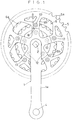
- Fig. 1 is a side view of a chain wheel assembly for a bicycle according to the present invention.
- Fig. 2 is a sectional view of the chain wheel assembly.
- Fig. 3 is a front view of a boss of a crank arm.
- Fig. 4 is a back view of the boss of the crank arm.
- Fig. 5 is an explanatory view of a coupling leg and a wheel mounting extension arranged adjacent each other.
- Fig. 6 is a further explanatory view of the coupling leg and wheel mounting extension arranged adjacent each other.
- Fig. 7 is a further explanatory view of the coupling leg and wheel mounting extension arranged adjacent each other.
- Fig. 8 is a further explanatory view of the coupling leg and wheel mounting extension arranged adjacent each other.
- Fig. 9 is a further explanatory view of the coupling leg and wheel mounting extension arranged adjacent each other.
- Fig. 10 is an explanatory view of the coupling leg and wheel mounting extension arranged with a space therebetween.
- Fig. 11 is a sectional view of a chain wheel assembly in another embodiment of the invention.
- Fig. 12 is a sectional view of a chain wheel assembly in a further embodiment of the invention.
- Fig. 13 is a sectional view of a conventional chain wheel assembly.
- a bicycle crank arm 1 formed by forging aluminum alloy includes an arm body 1a, and a crank axle connecting boss 3 integral with the arm body 1a.
- the boss 3 includes a tubular portion 3a projecting backward from one end of the arm body 1a and defining a crank axle connecting bore 2, and a flange portion 3b continuous from the tubular portion 3a.
- the arm body 1a has a pedal mounting bore 4 formed in the other end thereof.
- the crank arm 1 carries, on one end portion thereof, a large, high speed chain wheel 5, an intermediate speed chain wheel 6 smaller than the high speed chain wheel 5, and a low speed chain wheel 7 smaller than the intermediate speed chain wheel 6, which constitute a bicycle chain wheel assembly for providing three speeds.
- the crank arm 1 is connected through the boss 3 to a crank axle 9 supported in a bottom bracket 8 of a bicycle frame.
- the crank arm 1 is turned to drive the chain wheels 5-7 for transmitting drive to a rear wheel through a chain C.
- the crank arm 1 For connecting the chain wheels 5-7 to the crank arm 1, as shown in Figs. 3 and 4, the crank arm 1 includes five wheel mounting extensions 10 extending radially from the boss 3 about an axis Z of the crank axle connecting bore 2 in the boss 3. These extensions 10 are formed integral with the boss 3 by forging. Five wheel mounting pins 11 project inwardly of the bicycle from end regions of the extensions 10, respectively, which are formed integral with the extensions 10 by forging.
- the chain wheels 5-7 are connected through a connecting structure as shown in Figs. 1 and 2.
- the low speed chain wheel 7 is secured at inner peripheries thereof tight to the wheel mounting pins 11 by mounting screws 12.
- the intermediate speed chain wheel 6 includes an annular portion defining teeth 6a, and five coupling legs 6b extending from the annular portion toward a rotational axis of the wheels.
- the coupling legs 6b are arranged opposite inward surfaces of the wheel mounting extensions 10, and tightened to the wheel mounting pins 11 by the mounting screws 12.
- the high speed chain wheel 5 includes an annular portion defining teeth 5a, and five coupling legs 5b extending from the annular portion toward the rotational axis of the wheels.
- the coupling legs 5b are arranged in a positional relationship with the wheel mounting extensions 10 as shown in Fig. 1. These coupling legs 5b are not connected to the wheel mounting extensions 10, but connected to the coupling legs 6b of the intermediate speed chain wheel 6 by coupling screws 13, respectively.
- the intermediate speed chain wheel 6 and low speed chain wheel 7 are connected tight to the wheel mounting extensions 10, to be attachable or detachable together in a single operation.
- the two chain wheels 6 and 7 share the same connecting structure for connection to the crank arm 1.
- the high speed chain wheel 5 is connected to the intermediate speed chain wheel 6 without being connected to the crank arm 1.
- the high speed chain wheel 5 is connected to the crank arm 1 through the intermediate speed chain wheel 6, so that the high speed chain wheel 5 may be formed lightweight and the crank arm 1 may be reduced in size.
- the wheel mounting extensions 10 of the crank arm 1 define end surfaces A arranged inwardly toward the rotational axis from the screws 13 interconnecting the high speed chain wheel 5 and intermediate speed chain wheel 6. Even where end surfaces B of the coupling legs 5b of the high speed chain wheel 5 form a large inside diameter as in the prior art shown in Fig. 13, the wheel mounting extensions 10 may extend to a smaller extent from the boss 3 of the crank arm 1 than in the prior art. That is, the high speed chain wheel 5 may be connected to the crank arm 1 even where the wheel mounting extensions 10 have a reduced length such that the end surfaces A of the wheel mounting extensions 10 describe a circle S having a diameter not exceeding 95mm.
- the coupling legs 5b of the high speed chain wheel 5 are not connected to the wheel mounting extensions 10 of the crank arm 1, the end surfaces A of the, wheel mounting extensions 10 and the end surfaces B of the coupling legs 5b are arranged opposite and adjacent each other to provide for improvement in appearance and strength.
- the end surfaces A and B may be spaced from each other by a distance D not exceeding 3mm. Then, as in Fig. 8, the outer lateral surfaces X of the wheel mounting extensions 10 and outer lateral surfaces Y of the coupling legs 5b appear smoothly continuous with each other despite the space D therebetween.
- a slight offset T1 may be allowed, as in Figs. 10 and 11, between the outer lateral surfaces X of the wheel mounting extensions 10 and outer lateral surfaces Y of the coupling legs 5b.
- a slight offset T2 may be allowed, as in Fig. 9, between the side surfaces W of the wheel mounting extensions 10 and side surfaces V of the coupling legs 5b.
- an appearance of smooth continuation may be secured by limiting the offset T1 or T2 to 3mm.
- each wheel mounting pin 11 defines a bottomed thread hole 11a opening only to the inward surface of the wheel mounting extension 10. That is, the thread hole 11a does not extend to the front surface of the crank arm 1.
- the front surface of the crank arm 1 has a simple, neat appearance.
- the wheel mounting pins 11 are arranged in positions closer than positions P where the wheel mounting extensions 10 are connected to the flange portion 3b of the boss 3, to tip ends of the wheel mounting extensions 10. Consequently, relatively large spaces are secured between the tubular portion 3a and wheel mounting pins 11 although the wheel mounting extensions 10 have a relatively small length from the boss 3.
- This arrangement provides relatively large operating spaces adjacent the wheel mounting pins 11 for facility of an operation to attach the chain wheels 6 and 7.
- the tubular portion 3a may have a relatively large wall thickness to attain a rigid connection to the crank axle 9.
- Fig. 12 shows a chain wheel assembly in a different embodiment of the invention.
- the high speed chain wheel 5 has coupling legs 5b welded to the intermediate speed chain wheel 6.
- the intermediate speed chain wheel 6 and low speed chain wheel 7 are tightened to the wheel mounting extensions 10 by caulking heads of wheel mounting pins 14 of the crank arm 1.
- the high speed chain wheel 5 shown in Fig. 12 has a chain guide 15.
- the end surfaces A of the wheel mounting extensions 10 and the end surfaces B of the coupling legs 5b are opposed to each other.
- the ends of the wheel mounting extensions 10 may be displaced from the ends of the coupling legs 5b outwardly of the high speed chain wheel 5, such that the end surfaces A and B are equidistant from the axis Z and arranged along the rotational axis of the chain wheels.
- the ends of the wheel mounting extensions 10 and coupling legs 5b may be slightly displaced from each other both radially and axially.
- the object of the present invention may be fulfilled by arranging the end surfaces A of the wheel mounting extensions 10 in contact with or slightly spaced from the coupling legs 5b of the high speed chain wheel 5, the end surfaces A being closer to the rotational axis of the chain wheels than are the connections between the high speed chain wheel 5 and intermediate speed chain wheel 6.
- the present invention is applicable also to a chain wheel assembly providing two speeds instead of three. That is, the invention is applicable to a chain wheel assembly having at least one large chain wheel, and at least one smaller chain wheel.
Landscapes
- Engineering & Computer Science (AREA)
- Chemical & Material Sciences (AREA)
- Combustion & Propulsion (AREA)
- Transportation (AREA)
- Mechanical Engineering (AREA)
- Gears, Cams (AREA)
- Devices For Conveying Motion By Means Of Endless Flexible Members (AREA)
- Shafts, Cranks, Connecting Bars, And Related Bearings (AREA)
Claims (11)
- Ensemble de roues à chaîne de bicyclette comprenant:- une grande roue à chaîne (5) ;- une petite roue à chaîne (6) ;- un bras de manivelle (1) pour supporter ladite grande roue à chaîne et ladite petite roue à chaîne, ledit bras de manivelle ayant :- une unité de bras (1a) ;- un bossage (3) pour relier ledit bras de manivelle à un essieu de manivelle (9) de ladite bicyclette ; et des prolongements de montage de roue (10) partant radialement vers l'extérieur dudit bossage et comprenant un premier moyen de liaison (11, 12, 14) pour relier ladite petite roue à chaîne audit bossage ;- un second moyen de liaison (13) monté radialement vers l'extérieur dudit premier moyen de liaison pour relier ladite grande roue à chaîne à ladite petite roue à chaîne, ladite grande roue à chaîne étant reliée uniquement à ladite petite roue à chaîne par ledit second moyen de liaison.
- Ensemble de roues à chaîne selon la revendication 1, dans lequel ladite grande roue à chaîne comprend des pattes d'accouplement (5b) pour relier ladite petite roue à chaîne, lesdites pattes d'accouplement définissant des premières surfaces d'extrémité (B) orientées radialement vers l'intérieur, lesdits prolongements de montage de roue définissant des secondes surfaces d'extrémité (A) orientées radialement vers l'extérieur, lesdites premières surfaces d'extrémité et lesdites secondes surfaces d'extrémité étant en contact entre elles.
- Ensemble de roues à chaîne selon la revendication 2, dans lequel des surfaces latérales extérieures (X) desdits prolongements de montage de roue prolongent régulièrement des surfaces latérales extérieures (Y) desdits pattes d'accouplement contiguës aux positions de contact entre lesdites premières surfaces d'extrémité et lesdites secondes surfaces d'extrémité.
- Ensemble de roues à chaîne selon la revendication 2, dans lequel des surfaces latérales (V) desdits prolongements de montage de roue, quand on regarde dans une direction confondue avec un axe de rotation de ladite grande roue à chaîne et de ladite petite roue à chaîne, prolongent régulièrement des surfaces latérales (W) desdits pattes d'accouplement adjacentes aux positions de contact entre lesdites premières surfaces d'extrémité et lesdites secondes surfaces d'extrémité.
- Ensemble de roues à chaîne selon la revendication 1, dans lequel ladite grande roue à chaîne comprend des pattes d'accouplement pour relier ladite petite roue à chaîne, lesdites pattes d'accouplement définissant des première surfaces d'extrémité (B) orientées radialement vers l'intérieur, lesdits prolongements de montage de chaîne définissant des secondes surfaces d'extrémité orientées radialement vers l'extérieur (A), lesdites premières surfaces d'extrémité et lesdites secondes surfaces d'extrémité étant placées adjacentes mais sans être en contact les unes avec les autres.
- Ensemble de roues à chaîne selon la revendication 1, dans lequel ladite petite roue à chaîne est une roue à chaîne de vitesse intermédiaire, ledit montage de roue à chaîne comprenant encore une roue à chaîne (7) de faible vitesse plus petite que ladite roue à chaîne de vitesse intermédiaire, ladite roue à chaîne intermédiaire et ladite roue à chaîne de faible vitesse étant ensemble étroitement reliée auxdits prolongements de montage de roue.
- Ensemble de roues à chaîne selon la revendication 1, dans lequel lesdits premiers moyens de liaison sont des ergots (11) dépassant vers l'intérieur desdits prolongements de montage de roue et présentant des orifices borgnes filetés (11a) s'ouvrant uniquement vers les surfaces intérieures desdits prolongements de montage de roue.
- Ensemble de roues à chaîne selon la revendication 1, dans lequel lesdits premiers moyens de liaison sont des ergots (14) dépassant vers l'intérieur desdits prolongements de montage de roue et ayant des têtes matées pour fixer ladite petite roue à chaîne telle qu'engagée sur lesdits prolongements de montage de roue.
- Montage de roue à chaîne selon la revendication 1, dans lequel cinq desdits prolongements (10) de montage de roue font partie intégrante dudit bossage et partent radialement d'un axe dudit bossage, lesdits prolongements de montage de roue délimitant des surfaces d'extrémité décrivant un cercle imaginaire dont le diamètre peut atteindre 95 mm.
- Bras de manivelle (1) pour une bicyclette comprenant :- une unité de bras (1a) comprenant un bossage d'extrémité (3) pour liaison avec un essieu de manivelle ; et- cinq prolongements de montage de roue (10) faisant partie intégrante dudit bossage d'extrémité et partant radialement vers l'extérieur d'un axe (Z) dudit bossage, lesdits prolongements de montage de roue comprenant des moyens de liaison de roue (11, 12, 14) disposés radialement vers l'extérieur des positions dans lesquelles les prolongement de montage de roue sont reliés audit bossage;
lesdits prolongements de montage de roue définissant les surfaces d'extrémité les plus extérieures qui décrivent un cercle imaginaire ayant un diamètre pouvant atteindre 95mm. - Bras de manivelle selon la revendication 10, dans lequel au moins ladite unité de bras (1a) et lesdits prolongements de montage de roue (10) sont formés en alliage d'aluminium forgé.
Applications Claiming Priority (2)
| Application Number | Priority Date | Filing Date | Title |
|---|---|---|---|
| JP009787U JPH0667289U (ja) | 1993-03-09 | 1993-03-09 | 自転車用フロントギヤ装置とこのフロントギヤ装置に使用する自転車用クランク |
| JP9787/93U | 1993-03-09 |
Publications (3)
| Publication Number | Publication Date |
|---|---|
| EP0619220A2 EP0619220A2 (fr) | 1994-10-12 |
| EP0619220A3 EP0619220A3 (fr) | 1994-11-17 |
| EP0619220B1 true EP0619220B1 (fr) | 1996-11-06 |
Family
ID=11729941
Family Applications (1)
| Application Number | Title | Priority Date | Filing Date |
|---|---|---|---|
| EP94103304A Expired - Lifetime EP0619220B1 (fr) | 1993-03-09 | 1994-03-04 | Montage de roue de chaîne de bicyclette et un bras de manivelle à utiliser avec le montage de roue de chaîne |
Country Status (5)
| Country | Link |
|---|---|
| US (1) | US5480359A (fr) |
| EP (1) | EP0619220B1 (fr) |
| JP (1) | JPH0667289U (fr) |
| CN (1) | CN1034720C (fr) |
| DE (1) | DE69400837T2 (fr) |
Families Citing this family (30)
| Publication number | Priority date | Publication date | Assignee | Title |
|---|---|---|---|---|
| JP3708526B2 (ja) * | 2003-02-18 | 2005-10-19 | 株式会社シマノ | 自転車用クランク組立体 |
| JP2909010B2 (ja) * | 1995-09-20 | 1999-06-23 | 株式会社シマノ | 自転車用ギヤクランク |
| US5782713A (en) * | 1995-12-06 | 1998-07-21 | Yang; Shu-Chiung C. | Bicycle gear crank arresting device |
| EP0857137A4 (fr) * | 1995-11-10 | 1999-02-03 | Yang Ge Ind Co Ltd | Dispositif d'arret de manivelle d'engrenage de bicyclette |
| DE19717463A1 (de) * | 1997-04-25 | 1998-10-29 | Sram De Gmbh | Kurbelarm mit Mehrfachkettenrad für Fahrräder |
| US5979923A (en) * | 1998-07-08 | 1999-11-09 | Chiang; Douglas | Bicycle with an improved crank gearwheel assembly |
| JP3696190B2 (ja) * | 2002-08-28 | 2005-09-14 | 株式会社シマノ | 自転車用回転検出装置 |
| JP4048536B2 (ja) * | 2002-11-21 | 2008-02-20 | 宮田工業株式会社 | 自転車用自動張力調整機構付きベルト動力伝達装置 |
| DE10260565B4 (de) * | 2002-12-21 | 2016-09-15 | Sram Deutschland Gmbh | Zahnkranzpaket |
| US20060094550A1 (en) * | 2004-11-01 | 2006-05-04 | Shimano Inc. | Bicycle crankset |
| US7462120B1 (en) * | 2005-02-03 | 2008-12-09 | Thompson Scott C | Warped chain ring gear used in a bicycle chain transfer |
| DE102005005376A1 (de) * | 2005-02-05 | 2006-08-10 | Bayerische Motoren Werke Ag | Antriebsrad |
| US20080161146A1 (en) * | 2006-12-28 | 2008-07-03 | Shimano Inc. | Bicycle chain wheel with fastener covers |
| US20080161145A1 (en) * | 2006-12-28 | 2008-07-03 | Shimano Inc. | Bicycle chain wheel with fastener cover |
| US8888629B2 (en) * | 2007-05-23 | 2014-11-18 | Shimano Inc. | Bicycle sprocket assembly with chain protector |
| US20100009794A1 (en) * | 2008-07-10 | 2010-01-14 | Douglas Chiang | Sprocket assembly |
| EP2985214A3 (fr) * | 2009-03-16 | 2016-03-30 | Cycling Sports Group, Inc. | Ensemble unitaire de fourche de couronne et procédé de fabrication |
| US20110319209A1 (en) * | 2010-06-28 | 2011-12-29 | TWDT Precision Co., Ltd. | Integrated bicycle chainring assembly |
| US9771128B2 (en) * | 2011-10-05 | 2017-09-26 | Shimano Inc. | Bicycle crank assembly |
| EP2746620A1 (fr) * | 2012-12-18 | 2014-06-25 | Chang Hui Lin | Roue à chaîne pour bicyclette |
| DE102015203708A1 (de) * | 2015-03-02 | 2016-09-08 | Sram Deutschland Gmbh | Zahnrad für einen Fahrradantrieb |
| US10377445B2 (en) | 2016-09-20 | 2019-08-13 | Shimano Inc. | Bicycle front sprocket assembly |
| US10093389B2 (en) * | 2016-11-16 | 2018-10-09 | Shimano Inc. | Bicycle front sprocket, bicycle crank assembly, and bicycle drive train |
| JP6883751B2 (ja) * | 2016-11-24 | 2021-06-09 | ▲浜▼元 陽一郎 | 回転伝達機構及びそれを備えた自転車 |
| DE102017000855A1 (de) * | 2017-01-31 | 2018-08-02 | Sram Deutschland Gmbh | Mehrfach-Ritzelanordnung mit Schweißverbindung |
| US20180257742A1 (en) * | 2017-03-13 | 2018-09-13 | Drivetrain Tech Solution Inc. | Sprocket assembly of bicycle |
| CN107933812B (zh) * | 2017-11-22 | 2023-06-23 | 湖南耐特材料科技有限公司 | 一种高刚性一体式飞轮 |
| US11148753B2 (en) | 2017-12-20 | 2021-10-19 | Sram, Llc | Sprocket assembly |
| US11292555B2 (en) * | 2018-08-01 | 2022-04-05 | Shimano Inc. | Bicycle sprocket |
| FR3128690B1 (fr) * | 2021-11-02 | 2024-02-16 | Centre Nat Rech Scient | Dispositif de changement de rapport de réduction |
Family Cites Families (8)
| Publication number | Priority date | Publication date | Assignee | Title |
|---|---|---|---|---|
| GB704207A (en) * | 1950-12-13 | 1954-02-17 | Georges Navet | Means for the mounting of toothed wheels on the crank hubs of cycles |
| US3815439A (en) * | 1972-10-20 | 1974-06-11 | Shimano Industrial Co | Multi-speed transmission front gear system |
| US4380445A (en) * | 1974-08-16 | 1983-04-19 | Shimano Industrial Company Limited | Transmission for a bicycle |
| US4009621A (en) * | 1976-03-03 | 1977-03-01 | Shimano Industrial Company, Limited | Assembly of chain sprockets and cranks for bicycle |
| DE2861860D1 (en) * | 1977-12-28 | 1982-07-08 | Shimano Industrial Co | Chain wheel and crank assembly for a cycle |
| JP2939274B2 (ja) * | 1989-09-12 | 1999-08-25 | 株式会社シマノ | 自転車用多段スプロケットホイール |
| JPH0378694U (fr) * | 1989-12-05 | 1991-08-09 | ||
| JPH04119795U (ja) * | 1991-04-11 | 1992-10-27 | 株式会社シマノ | 自転車用ギアクランク装置 |
-
1993
- 1993-03-09 JP JP009787U patent/JPH0667289U/ja active Pending
-
1994
- 1994-03-03 US US08/205,412 patent/US5480359A/en not_active Expired - Lifetime
- 1994-03-04 EP EP94103304A patent/EP0619220B1/fr not_active Expired - Lifetime
- 1994-03-04 DE DE69400837T patent/DE69400837T2/de not_active Expired - Lifetime
- 1994-03-09 CN CN94102464A patent/CN1034720C/zh not_active Expired - Fee Related
Also Published As
| Publication number | Publication date |
|---|---|
| US5480359A (en) | 1996-01-02 |
| EP0619220A2 (fr) | 1994-10-12 |
| CN1034720C (zh) | 1997-04-30 |
| CN1097173A (zh) | 1995-01-11 |
| JPH0667289U (ja) | 1994-09-22 |
| EP0619220A3 (fr) | 1994-11-17 |
| DE69400837D1 (de) | 1996-12-12 |
| DE69400837T2 (de) | 1997-03-06 |
Similar Documents
| Publication | Publication Date | Title |
|---|---|---|
| EP0619220B1 (fr) | Montage de roue de chaîne de bicyclette et un bras de manivelle à utiliser avec le montage de roue de chaîne | |
| US20010002966A1 (en) | Expansion shaft | |
| US20020167199A1 (en) | Structure of a cowl cross member mounting unit | |
| US5653007A (en) | Method for producing a bicycle fork brake arch and legs assembly | |
| EP1004496A3 (fr) | Volant de direction, structure de montage et structure de moyeu pour cela | |
| JPH0960703A (ja) | 駆動装置 | |
| JPH0331001A (ja) | 自動車の車輪用軸受装置 | |
| JP3143170B2 (ja) | 連動杆 | |
| CN109421879B (zh) | 曲柄臂 | |
| US6554713B2 (en) | Coupling for coupling two shafts | |
| JP2000103301A (ja) | バンパーサイドの取付構造 | |
| JP2872989B1 (ja) | 車両の操向装置 | |
| EP1241071B1 (fr) | Colonne de direction de véhicule | |
| JPH0138669Y2 (fr) | ||
| JPH01212683A (ja) | オートバイのフレーム | |
| JPH0215130Y2 (fr) | ||
| CN217730649U (zh) | 一种扶手结构和电动车 | |
| JPH0528148Y2 (fr) | ||
| JPS632390Y2 (fr) | ||
| JP2531612Y2 (ja) | 子供用自転車の補助車 | |
| US5063664A (en) | Process for manufacturing wheel hub | |
| JPS642875Y2 (fr) | ||
| JPH11139376A (ja) | 自動二輪車のチェーンケース | |
| JPS594868Y2 (ja) | 自転車用スプロケツトホイ−ル | |
| JPS633917Y2 (fr) |
Legal Events
| Date | Code | Title | Description |
|---|---|---|---|
| PUAI | Public reference made under article 153(3) epc to a published international application that has entered the european phase |
Free format text: ORIGINAL CODE: 0009012 |
|
| PUAL | Search report despatched |
Free format text: ORIGINAL CODE: 0009013 |
|
| AK | Designated contracting states |
Kind code of ref document: A2 Designated state(s): DE FR GB IT |
|
| AK | Designated contracting states |
Kind code of ref document: A3 Designated state(s): DE FR GB IT |
|
| 17P | Request for examination filed |
Effective date: 19950505 |
|
| GRAG | Despatch of communication of intention to grant |
Free format text: ORIGINAL CODE: EPIDOS AGRA |
|
| 17Q | First examination report despatched |
Effective date: 19960117 |
|
| GRAH | Despatch of communication of intention to grant a patent |
Free format text: ORIGINAL CODE: EPIDOS IGRA |
|
| GRAH | Despatch of communication of intention to grant a patent |
Free format text: ORIGINAL CODE: EPIDOS IGRA |
|
| GRAA | (expected) grant |
Free format text: ORIGINAL CODE: 0009210 |
|
| ITF | It: translation for a ep patent filed | ||
| AK | Designated contracting states |
Kind code of ref document: B1 Designated state(s): DE FR GB IT |
|
| REF | Corresponds to: |
Ref document number: 69400837 Country of ref document: DE Date of ref document: 19961212 |
|
| ET | Fr: translation filed | ||
| PLBE | No opposition filed within time limit |
Free format text: ORIGINAL CODE: 0009261 |
|
| STAA | Information on the status of an ep patent application or granted ep patent |
Free format text: STATUS: NO OPPOSITION FILED WITHIN TIME LIMIT |
|
| 26N | No opposition filed | ||
| REG | Reference to a national code |
Ref country code: GB Ref legal event code: IF02 |
|
| PGFP | Annual fee paid to national office [announced via postgrant information from national office to epo] |
Ref country code: GB Payment date: 20060301 Year of fee payment: 13 |
|
| GBPC | Gb: european patent ceased through non-payment of renewal fee |
Effective date: 20070304 |
|
| PG25 | Lapsed in a contracting state [announced via postgrant information from national office to epo] |
Ref country code: GB Free format text: LAPSE BECAUSE OF NON-PAYMENT OF DUE FEES Effective date: 20070304 |
|
| PGFP | Annual fee paid to national office [announced via postgrant information from national office to epo] |
Ref country code: IT Payment date: 20100313 Year of fee payment: 17 Ref country code: FR Payment date: 20100324 Year of fee payment: 17 |
|
| PGFP | Annual fee paid to national office [announced via postgrant information from national office to epo] |
Ref country code: DE Payment date: 20100312 Year of fee payment: 17 |
|
| REG | Reference to a national code |
Ref country code: FR Ref legal event code: ST Effective date: 20111130 |
|
| PG25 | Lapsed in a contracting state [announced via postgrant information from national office to epo] |
Ref country code: DE Free format text: LAPSE BECAUSE OF NON-PAYMENT OF DUE FEES Effective date: 20111001 Ref country code: FR Free format text: LAPSE BECAUSE OF NON-PAYMENT OF DUE FEES Effective date: 20110331 |
|
| REG | Reference to a national code |
Ref country code: DE Ref legal event code: R119 Ref document number: 69400837 Country of ref document: DE Effective date: 20111001 |
|
| PG25 | Lapsed in a contracting state [announced via postgrant information from national office to epo] |
Ref country code: IT Free format text: LAPSE BECAUSE OF NON-PAYMENT OF DUE FEES Effective date: 20110304 |