EP0619421A2 - Steuersystem für eine Zweitaktbrennkraftmaschine - Google Patents
Steuersystem für eine Zweitaktbrennkraftmaschine Download PDFInfo
- Publication number
- EP0619421A2 EP0619421A2 EP94200225A EP94200225A EP0619421A2 EP 0619421 A2 EP0619421 A2 EP 0619421A2 EP 94200225 A EP94200225 A EP 94200225A EP 94200225 A EP94200225 A EP 94200225A EP 0619421 A2 EP0619421 A2 EP 0619421A2
- Authority
- EP
- European Patent Office
- Prior art keywords
- engine
- air
- throttle plate
- throttle
- fuel
- Prior art date
- Legal status (The legal status is an assumption and is not a legal conclusion. Google has not performed a legal analysis and makes no representation as to the accuracy of the status listed.)
- Withdrawn
Links
Images


Classifications
-
- F—MECHANICAL ENGINEERING; LIGHTING; HEATING; WEAPONS; BLASTING
- F02—COMBUSTION ENGINES; HOT-GAS OR COMBUSTION-PRODUCT ENGINE PLANTS
- F02D—CONTROLLING COMBUSTION ENGINES
- F02D9/00—Controlling engines by throttling air or fuel-and-air induction conduits or exhaust conduits
- F02D9/02—Controlling engines by throttling air or fuel-and-air induction conduits or exhaust conduits concerning induction conduits
-
- F—MECHANICAL ENGINEERING; LIGHTING; HEATING; WEAPONS; BLASTING
- F02—COMBUSTION ENGINES; HOT-GAS OR COMBUSTION-PRODUCT ENGINE PLANTS
- F02B—INTERNAL-COMBUSTION PISTON ENGINES; COMBUSTION ENGINES IN GENERAL
- F02B25/00—Engines characterised by using fresh charge for scavenging cylinders
- F02B25/14—Engines characterised by using fresh charge for scavenging cylinders using reverse-flow scavenging, e.g. with both outlet and inlet ports arranged near bottom of piston stroke
-
- F—MECHANICAL ENGINEERING; LIGHTING; HEATING; WEAPONS; BLASTING
- F02—COMBUSTION ENGINES; HOT-GAS OR COMBUSTION-PRODUCT ENGINE PLANTS
- F02D—CONTROLLING COMBUSTION ENGINES
- F02D9/00—Controlling engines by throttling air or fuel-and-air induction conduits or exhaust conduits
- F02D9/08—Throttle valves specially adapted therefor; Arrangements of such valves in conduits
- F02D9/10—Throttle valves specially adapted therefor; Arrangements of such valves in conduits having pivotally-mounted flaps
-
- F—MECHANICAL ENGINEERING; LIGHTING; HEATING; WEAPONS; BLASTING
- F02—COMBUSTION ENGINES; HOT-GAS OR COMBUSTION-PRODUCT ENGINE PLANTS
- F02B—INTERNAL-COMBUSTION PISTON ENGINES; COMBUSTION ENGINES IN GENERAL
- F02B75/00—Other engines
- F02B75/02—Engines characterised by their cycles, e.g. six-stroke
- F02B2075/022—Engines characterised by their cycles, e.g. six-stroke having less than six strokes per cycle
- F02B2075/025—Engines characterised by their cycles, e.g. six-stroke having less than six strokes per cycle two
-
- F—MECHANICAL ENGINEERING; LIGHTING; HEATING; WEAPONS; BLASTING
- F02—COMBUSTION ENGINES; HOT-GAS OR COMBUSTION-PRODUCT ENGINE PLANTS
- F02D—CONTROLLING COMBUSTION ENGINES
- F02D9/00—Controlling engines by throttling air or fuel-and-air induction conduits or exhaust conduits
- F02D9/02—Controlling engines by throttling air or fuel-and-air induction conduits or exhaust conduits concerning induction conduits
- F02D2009/0201—Arrangements; Control features; Details thereof
- F02D2009/0244—Choking air flow at low speed and load
Definitions
- the invention relates to control system for a crankcase scavenged, two-stroke engine, and more particularly to a control system for reducing the exhaust gas hydrocarbons emitted from such an engine.
- crankcase scavenged, two-stroke engines differ in many respects from that of conventional four-stroke engines.
- One difference concerns the manner in which fresh air is inducted, and burned fuel is exhausted by the engines.
- Conventional four-stroke engines have intake and exhaust valves within the cylinders to accomplish these tasks.
- Crankcase scavenged, two-stroke engines do not employ intake and exhaust valves but rather, intake and exhaust ports which open directly through the walls of the engine cylinders.
- the piston moves in its down stroke within a cylinder, uncovering the exhaust port for release of the burned fuel, and shortly thereafter, uncovering the intake port to enable the entry of a fresh air charge, and assist in expulsion of the combustion components of the burned fuel.
- a control system in accordance with the present invention is characterised by the features specified in Claim 1.
- the fuel per cylinder delivered to the engine is increased, however, the air per cylinder delivered to the engine is restricted, to be less than that delivered at unloaded engine idle. This results in a reduced level of hydrocarbons in the exhaust gas for the crankcase scavenged two-stroke engine, even though this practice is contrary to that typically used with four-stroke engines.
- exhaust gas hydrocarbons are reduced by decreasing the mass of air per cylinder delivered to the engine, from that delivered at unloaded engine idle, as the demand for engine output is increased.
- this is accomplished by utilising a throttle body with over centre travel such that operator demand for an increase in power results in an initial throttle plate movement which decreases the mass of air per cylinder delivered to the engine through a reduction in the throttle bore area.
- a throttle position sensor relates information regarding the throttle position to the engine electronic control module (ECM) to be used as input for engine fuelling. Any increase in throttle position is translated into an increase in the quantity of fuel delivered to the cylinder. Consequently, fuel is increased with a reduction in mass of air per cylinder as demand for engine power is increased from an idle condition.
- ECM engine electronic control module
- FIG. 1 there is shown schematically a crankcase scavenged, two-stroke engine, designated generally as 10, with a portion of the engine exterior cut away, exposing cylinder 12.
- Piston 14 resides within cylinder 12 and is mounted to connecting rod 16 and crankshaft 18 for reciprocating motion therein.
- Operably connected to the engine 10 is intake manifold 20 and exhaust manifold 22.
- Cylinder 12 communicates with the exhaust manifold 22 through exhaust port 24 in the wall of cylinder 12.
- Intake manifold 22 likewise communicates with cylinder 12 through intake port 26.
- a reed valve checking mechanism 28 may be situated at the entrance to a common air transfer passage 30 which links crankcase port 32 with the intake port 26 in the wall of cylinder 12.
- Cylinder 12 is provided with a spark plug 34 and a fuel injector 36 which is preferably of the electronic solenoid driven type.
- ECM 38 is typically a conventional digital computer used by those skilled in the art of engine control, and includes the standard elements of a central processing unit, random access memory, read only memory, analogue-to-digital converter, input/output circuitry, and clock circuitry.
- the ECM 38 is suited to receive information on various engine parameters from sensors connected to the engine 10. Upon receipt of such information, the ECM 38 performs required computations and provides output signals which are transmitted to various operating systems which affect the operation of the engine 10. The operation of the engine 10 will now be briefly described based on the cycle operating in cylinder 12. During the upstroke, piston 14 moves from its lowest position in cylinder 12 toward top dead centre.
- piston 14 uncovers exhaust port 24 to release the combusted fuel, followed by an uncovering of the intake port 26, enabling the air compressed within the crankcase chamber 42 to flow through the air transfer passage 30 and into cylinder 12.
- the cycle begins anew when piston 14 reaches the bottom of its travel in cylinder 12.
- FIG. 5 there is shown a graph of typical speed load data for a crankcase scavenged, two-stroke engine.
- the data was obtained from standard dynamometer measurements known to those skilled in the art of engine control.
- the desired engine air flow, to minimise exhaust gas hydrocarbons, is given a function of the percentage of maximum engine loading for an engine speed of 800 RPM .
- the axis representing percentage of maximum engine loading is also equivalent to the percentage of maximum engine output power demanded by the operator.
- the engine air flow for minimum hydrocarbon emission must be decreased from that at unloaded idle, as operator demand for output power increases to approximately 35 percent of the maximum loading.
- the level of hydrocarbon emission may be unnecessarily high.
- the present invention is directed to a means of controlling the quantity of fuel and air delivered to a crankcase scavenged, two-stroke engine to reduce hydrocarbon emissions when the engine is operated near idle with light operator induced loading. This is accomplished using a throttle body with over-centre capability which restricts the mass of air per cylinder delivered to the engine 10 upon initial movement off of its idle position and through a defined range of engine operation.
- throttle plate 44 rotates about a throttle shaft 46 within the throat of throttle body 48 located in the intake manifold 20 to form a valve for controlling the quantity of air per cylinder delivered to the engine 10.
- Accelerator pedal 50 functions as an operator actuated control element, indicating the engine output power demanded by the operator.
- the accelerator pedal 50 and the throttle plate 44 may communicate with one another in any number of ways.
- Accelerator pedal 50 may be an integral part of an electronic pedal module which translates operator input into electrical signals which are transmitted to a throttle position device such as a stepper motor for positioning of the throttle plate 44 in conformity with operator input.
- the throttle plate 44 may be positioned by more conventional means such as a cable or linkage operated on directly by the accelerator pedal 50.
- a throttle position sensor 52 supplies a signal TP to ECM 38 indicating the percentage of engine output power demanded by the operator, or equivalently, the percentage of operator induced engine loading. Based on the position of the throttle plate 44 as indicated by the throttle position sensor 52, the ECM 38 is able to calculate the quantity of fuel per cylinder to supply to the engine 10. As throttle position increases from an idle position illustrated in Figure 3 to the open throttle position of Figure 4, fuel per cylinder is increased.
- throttle position sensor 52 is the preferred means by which the fuel is increased as the throttle plate 44 is rotated upon increased operator demand for engine power, it is contemplated that other means for increasing fuel, which dispense with throttle position sensor 52, may also be used.
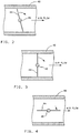
- the throttle plate 44 in the throttle body 48 has a range of rotation which extends from the wide open throttle (WOT) position of Figure 4 in which the throttle plate 44 is substantially parallel to the flow of air through the throttle body 48 and the throttle bore area available for air flow is maximised, to the idle position of Figure 2, corresponding to a steady state unloaded engine, in which the throttle plate 44 is positioned at a negative throttle angle relative to the fully closed, or centred location shown in Figure 3 in which the throttle plate 44 is positioned substantially perpendicular to the flow of air through the throttle body 48 and the throttle bore area available for air flow is minimised.
- WOT wide open throttle
- the throttle plate 44 rotates from the idle position in a clockwise direction as viewed in Figures 2, 3 and 4.
- the throttle bore area is reduced thereby reducing air flow to the engine 10 while fuel is increased due to rotation of the throttle plate 44 from the idle position.
- the simultaneous operation of the throttle bore area decreasing and the increased rotation of the throttle plate 44 as, translated by the throttle position sensor 52, resulting in an increase in fuel rate accomplishes the goal of decreasing air flow to the engine 10 ( Figure 5) while simultaneously increasing fuel rate ( Figure 6).
- the throttle body operation resembles that of a conventional throttle body in that an increase in operator demand for engine power results in an increase in engine air flow and fuel rate.
- the fuel control system described for application to a crankcase scavenged, two-stroke engine uses an over-centre throttle body to reduce the flow of air to the engine in off-idle situations while allowing for increasing fuel to be supplied to the engine based on the position of the throttle plate.
- the present system eliminates the need for complex linkages or electronically actuated air bypass valves which are prone to durability and cost concerns.
Landscapes
- Engineering & Computer Science (AREA)
- Chemical & Material Sciences (AREA)
- Combustion & Propulsion (AREA)
- Mechanical Engineering (AREA)
- General Engineering & Computer Science (AREA)
- Control Of Throttle Valves Provided In The Intake System Or In The Exhaust System (AREA)
- Electrical Control Of Air Or Fuel Supplied To Internal-Combustion Engine (AREA)
Applications Claiming Priority (2)
| Application Number | Priority Date | Filing Date | Title |
|---|---|---|---|
| US24140 | 1993-03-01 | ||
| US08/024,140 US5282448A (en) | 1993-03-01 | 1993-03-01 | Fuel control of a two-stroke engine with over-center throttle body |
Publications (2)
| Publication Number | Publication Date |
|---|---|
| EP0619421A2 true EP0619421A2 (de) | 1994-10-12 |
| EP0619421A3 EP0619421A3 (de) | 1995-05-10 |
Family
ID=21819058
Family Applications (1)
| Application Number | Title | Priority Date | Filing Date |
|---|---|---|---|
| EP94200225A Withdrawn EP0619421A3 (de) | 1993-03-01 | 1994-02-07 | Steuersystem für eine Zweitaktbrennkraftmaschine. |
Country Status (2)
| Country | Link |
|---|---|
| US (1) | US5282448A (de) |
| EP (1) | EP0619421A3 (de) |
Families Citing this family (5)
| Publication number | Priority date | Publication date | Assignee | Title |
|---|---|---|---|---|
| JP3715334B2 (ja) * | 1994-05-10 | 2005-11-09 | ヤマハマリン株式会社 | 船外機用エンジンの吸気装置 |
| AUPO094996A0 (en) * | 1996-07-10 | 1996-08-01 | Orbital Engine Company (Australia) Proprietary Limited | Engine fuelling rate control |
| US20080034743A1 (en) * | 2006-08-08 | 2008-02-14 | Arvin Technologies, Inc. | Unidirectional two position throttling exhaust valve |
| AT516758B1 (de) * | 2015-06-15 | 2016-08-15 | Forschungsgesellschaft für Verbrennungskraftmaschinen und Thermodynamik mbH | Verfahren zum Betreiben eines durch eine Drosselklappe steuerbaren Zweitakt-Ottomotors |
| AT516726B1 (de) * | 2015-06-15 | 2016-08-15 | Forschungsgesellschaft für Verbrennungskraftmaschinen und Thermodynamik mbH | Verfahren zum Betreiben eines durch eine Drosselklappe steuerbaren Zweitakt-Ottomotors |
Family Cites Families (13)
| Publication number | Priority date | Publication date | Assignee | Title |
|---|---|---|---|---|
| JPS5656938A (en) * | 1979-10-15 | 1981-05-19 | Nissan Motor Co Ltd | Apparatus for detecting opening of throttle valve |
| JPS57192674A (en) * | 1981-05-25 | 1982-11-26 | Mikuni Kogyo Co Ltd | Throttle valve |
| DE3205160C2 (de) * | 1982-02-13 | 1984-05-30 | Audi Nsu Auto Union Ag, 7107 Neckarsulm | Drosselklappe für eine im Querschnitt kreisförmige Ansaugleitung einer Brennkraftmaschine |
| US4474150A (en) * | 1982-11-22 | 1984-10-02 | General Motors Corporation | Valve assembly |
| US4491106A (en) * | 1982-11-29 | 1985-01-01 | Morris George Q | Throttle configuration achieving high velocity channel at partial opening |
| DE3737828A1 (de) * | 1987-11-06 | 1989-05-18 | Schatz Oskar | Verbrennungsmotor der kolbenbauart |
| US4905647A (en) * | 1988-06-20 | 1990-03-06 | Chrysler Motors Corporation | Throttle body |
| JPH0311135A (ja) * | 1989-06-08 | 1991-01-18 | Nippon Carbureter Co Ltd | エンジンの吸気量制御装置 |
| US4932371A (en) * | 1989-08-14 | 1990-06-12 | General Motors Corporation | Emission control system for a crankcase scavenged two-stroke engine operating near idle |
| US4955341A (en) * | 1989-09-18 | 1990-09-11 | General Motors Corporation | Idle control system for a crankcase scavenged two-stroke engine |
| US5146887A (en) * | 1990-07-12 | 1992-09-15 | General Motors Corporation | Valve assembly |
| CA2044213A1 (en) * | 1990-07-12 | 1992-01-13 | Paul L. Gluchowski | Valve assembly |
| JPH0533657A (ja) * | 1991-07-31 | 1993-02-09 | Mitsubishi Heavy Ind Ltd | 2サイクルエンジン |
-
1993
- 1993-03-01 US US08/024,140 patent/US5282448A/en not_active Expired - Fee Related
-
1994
- 1994-02-07 EP EP94200225A patent/EP0619421A3/de not_active Withdrawn
Also Published As
| Publication number | Publication date |
|---|---|
| EP0619421A3 (de) | 1995-05-10 |
| US5282448A (en) | 1994-02-01 |
Similar Documents
| Publication | Publication Date | Title |
|---|---|---|
| EP0382063A1 (de) | Mehrzylinder-Zweitaktbrennkraftmaschine | |
| EP0363021A1 (de) | Schnell ansprechendes System zur Abgasrückführung | |
| GB2226596A (en) | Regulating two-stroke engine intake and exhaust | |
| GB2290349A (en) | Fuel supply in crankcase scavenged two-stroke engines | |
| GB2172051A (en) | Multi-valve internal combustion engine | |
| EP0413432B1 (de) | Schadstoffregelungssystem für einen Zweitaktmotor mit Kurbelgehäusespülung beim leerlaufnahen Bereich | |
| EP0427334B1 (de) | Zweitakt-Brennkraftmaschine mit variabler Ventilsteuerung | |
| EP0071272A2 (de) | Durchflussregler für eine spiralige Einlassöffnung einer Dieselmaschine | |
| GB2219346A (en) | Two and four-stroke i.c. engine | |
| JP2716184B2 (ja) | 2サイクルエンジンの送油方法及びその装置 | |
| US5282448A (en) | Fuel control of a two-stroke engine with over-center throttle body | |
| JP2824663B2 (ja) | 内燃機関の燃料供給装置 | |
| EP0349149A2 (de) | Zweitaktbrennkraftmaschine | |
| US5572960A (en) | Two-cycle engine of the spark ignition type | |
| US4922864A (en) | System for controlling air intake for an automotive engine | |
| US5022367A (en) | Engine brake system of a two-cycle engine for a motor vehicle | |
| EP0268914A2 (de) | Vorrichtung zur Steuerung des Luft- oder Gemischstromes für Brennkraftmaschinen | |
| JP3183405B2 (ja) | 2サイクルディーゼルエンジンの給気装置 | |
| JP3073305B2 (ja) | 2サイクルエンジンの制御装置 | |
| JP2799220B2 (ja) | 2サイクルディーゼルエンジン | |
| JPS59158328A (ja) | 内燃機関 | |
| JP2536936Y2 (ja) | 内燃機関の吸気制御装置 | |
| JP2590894B2 (ja) | 内燃機関の空燃比制御装置 | |
| JPH08189386A (ja) | 2サイクルエンジンの空燃比検知装置 | |
| JPS6035538B2 (ja) | ヘリカル型吸気ポ−トの流路制御装置 |
Legal Events
| Date | Code | Title | Description |
|---|---|---|---|
| PUAI | Public reference made under article 153(3) epc to a published international application that has entered the european phase |
Free format text: ORIGINAL CODE: 0009012 |
|
| AK | Designated contracting states |
Kind code of ref document: A2 Designated state(s): DE GB IT |
|
| PUAL | Search report despatched |
Free format text: ORIGINAL CODE: 0009013 |
|
| AK | Designated contracting states |
Kind code of ref document: A3 Designated state(s): DE GB IT |
|
| 17P | Request for examination filed |
Effective date: 19951110 |
|
| 17Q | First examination report despatched |
Effective date: 19960124 |
|
| STAA | Information on the status of an ep patent application or granted ep patent |
Free format text: STATUS: THE APPLICATION IS DEEMED TO BE WITHDRAWN |
|
| 18D | Application deemed to be withdrawn |
Effective date: 19960604 |