EP0620633A1 - Moteur - Google Patents
Moteur Download PDFInfo
- Publication number
- EP0620633A1 EP0620633A1 EP94302554A EP94302554A EP0620633A1 EP 0620633 A1 EP0620633 A1 EP 0620633A1 EP 94302554 A EP94302554 A EP 94302554A EP 94302554 A EP94302554 A EP 94302554A EP 0620633 A1 EP0620633 A1 EP 0620633A1
- Authority
- EP
- European Patent Office
- Prior art keywords
- spindle
- inner race
- ball
- adhesive
- knurled
- Prior art date
- Legal status (The legal status is an assumption and is not a legal conclusion. Google has not performed a legal analysis and makes no representation as to the accuracy of the status listed.)
- Granted
Links
- 239000000853 adhesive Substances 0.000 claims abstract description 36
- 230000001070 adhesive effect Effects 0.000 claims abstract description 36
- 230000002093 peripheral effect Effects 0.000 claims abstract description 24
- 238000010276 construction Methods 0.000 description 1
- 239000000463 material Substances 0.000 description 1
- 238000000034 method Methods 0.000 description 1
- 238000005096 rolling process Methods 0.000 description 1
Images

Classifications
-
- H—ELECTRICITY
- H02—GENERATION; CONVERSION OR DISTRIBUTION OF ELECTRIC POWER
- H02K—DYNAMO-ELECTRIC MACHINES
- H02K5/00—Casings; Enclosures; Supports
- H02K5/04—Casings or enclosures characterised by the shape, form or construction thereof
- H02K5/16—Means for supporting bearings, e.g. insulating supports or means for fitting bearings in the bearing-shields
- H02K5/173—Means for supporting bearings, e.g. insulating supports or means for fitting bearings in the bearing-shields using bearings with rolling contact, e.g. ball bearings
- H02K5/1737—Means for supporting bearings, e.g. insulating supports or means for fitting bearings in the bearing-shields using bearings with rolling contact, e.g. ball bearings radially supporting the rotor around a fixed spindle; radially supporting the rotor directly
-
- F—MECHANICAL ENGINEERING; LIGHTING; HEATING; WEAPONS; BLASTING
- F16—ENGINEERING ELEMENTS AND UNITS; GENERAL MEASURES FOR PRODUCING AND MAINTAINING EFFECTIVE FUNCTIONING OF MACHINES OR INSTALLATIONS; THERMAL INSULATION IN GENERAL
- F16C—SHAFTS; FLEXIBLE SHAFTS; ELEMENTS OR CRANKSHAFT MECHANISMS; ROTARY BODIES OTHER THAN GEARING ELEMENTS; BEARINGS
- F16C19/00—Bearings with rolling contact, for exclusively rotary movement
- F16C19/02—Bearings with rolling contact, for exclusively rotary movement with bearing balls essentially of the same size in one or more circular rows
- F16C19/14—Bearings with rolling contact, for exclusively rotary movement with bearing balls essentially of the same size in one or more circular rows for both radial and axial load
- F16C19/18—Bearings with rolling contact, for exclusively rotary movement with bearing balls essentially of the same size in one or more circular rows for both radial and axial load with two or more rows of balls
-
- F—MECHANICAL ENGINEERING; LIGHTING; HEATING; WEAPONS; BLASTING
- F16—ENGINEERING ELEMENTS AND UNITS; GENERAL MEASURES FOR PRODUCING AND MAINTAINING EFFECTIVE FUNCTIONING OF MACHINES OR INSTALLATIONS; THERMAL INSULATION IN GENERAL
- F16C—SHAFTS; FLEXIBLE SHAFTS; ELEMENTS OR CRANKSHAFT MECHANISMS; ROTARY BODIES OTHER THAN GEARING ELEMENTS; BEARINGS
- F16C35/00—Rigid support of bearing units; Housings, e.g. caps, covers
- F16C35/04—Rigid support of bearing units; Housings, e.g. caps, covers in the case of ball or roller bearings
- F16C35/06—Mounting or dismounting of ball or roller bearings; Fixing them onto shaft or in housing
- F16C35/063—Fixing them on the shaft
-
- F—MECHANICAL ENGINEERING; LIGHTING; HEATING; WEAPONS; BLASTING
- F16—ENGINEERING ELEMENTS AND UNITS; GENERAL MEASURES FOR PRODUCING AND MAINTAINING EFFECTIVE FUNCTIONING OF MACHINES OR INSTALLATIONS; THERMAL INSULATION IN GENERAL
- F16D—COUPLINGS FOR TRANSMITTING ROTATION; CLUTCHES; BRAKES
- F16D1/00—Couplings for rigidly connecting two coaxial shafts or other movable machine elements
- F16D1/06—Couplings for rigidly connecting two coaxial shafts or other movable machine elements for attachment of a member on a shaft or on a shaft-end
- F16D1/064—Couplings for rigidly connecting two coaxial shafts or other movable machine elements for attachment of a member on a shaft or on a shaft-end non-disconnectable
- F16D1/068—Couplings for rigidly connecting two coaxial shafts or other movable machine elements for attachment of a member on a shaft or on a shaft-end non-disconnectable involving gluing, welding or the like
-
- F—MECHANICAL ENGINEERING; LIGHTING; HEATING; WEAPONS; BLASTING
- F16—ENGINEERING ELEMENTS AND UNITS; GENERAL MEASURES FOR PRODUCING AND MAINTAINING EFFECTIVE FUNCTIONING OF MACHINES OR INSTALLATIONS; THERMAL INSULATION IN GENERAL
- F16C—SHAFTS; FLEXIBLE SHAFTS; ELEMENTS OR CRANKSHAFT MECHANISMS; ROTARY BODIES OTHER THAN GEARING ELEMENTS; BEARINGS
- F16C2226/00—Joining parts; Fastening; Assembling or mounting parts
- F16C2226/30—Material joints
- F16C2226/40—Material joints with adhesive
-
- F—MECHANICAL ENGINEERING; LIGHTING; HEATING; WEAPONS; BLASTING
- F16—ENGINEERING ELEMENTS AND UNITS; GENERAL MEASURES FOR PRODUCING AND MAINTAINING EFFECTIVE FUNCTIONING OF MACHINES OR INSTALLATIONS; THERMAL INSULATION IN GENERAL
- F16C—SHAFTS; FLEXIBLE SHAFTS; ELEMENTS OR CRANKSHAFT MECHANISMS; ROTARY BODIES OTHER THAN GEARING ELEMENTS; BEARINGS
- F16C2370/00—Apparatus relating to physics, e.g. instruments
- F16C2370/12—Hard disk drives or the like
Definitions
- THE PRESENT INVENTION relates to a machine having a spindle received in a bore of a component thereby fixed to the spindle.
- the invention is of particular, but not exclusive, utility to the securing of the inner races of rolling element bearings, such as ball or roller bearings, to motor spindles, for example in motors employed in office equipment.
- a machine provided with a spindle to which a component having a bore to receive said spindle is fitted, characterised in that said spindle has a portion of an outer peripheral surface thereof received within said inner race knurled, said component being mounted on said knurled portion of said spindle; and a clearance between the surface of said bore of said component and the knurled portion of said spindle is filled with an adhesive through which said component is fixed to said spindle.
- a motor is provided with a spindle, an outer peripheral surface of an end portion of which is knurled.
- An inner race of a ball bearing is mounted on the knurled portion of the spindle.
- An adhesive is permitted to flow into an annular clearance formed between such knurled portion of the spindle and an inner surface of the inner race of the ball bearing, and is cured therein so that the inner race of the ball bearing is fixed to the spindle of the motor.
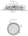
- FIG. 1 there is shown in outer-rotor type motor embodying the present invention, in which the reference numeral 1 denotes a base.
- a sleeve-like yoke holder 2 provided with a bottom portion is mounted on a central portion of the base 1.
- a stator yoke 4 Disposed around the yoke holder 2 is a stator yoke 4 which is provided with an energizing coil 3.
- a spindle 5 has its lower portion fixedly mounted in a centre hole of the bottom portion of the yoke holder 2 and has its upper portion formed into a small diameter shaft portion, so that the spindle 5 is constructed of a lower large-diameter shaft portion and the upper small-diameter shaft portion to form a stepped shaft.
- a ball-running groove 6 Formed in an outer peripheral portion of the lower large-diameter shaft portion of the spindle 5 is a ball-running groove 6.
- An inner race 8 of a ball bearing unit is fitted to the small-diameter shaft portion of the spindle 5, and provided with a ball running groove 7 in its outer peripheral portion.
- a sleeve portion 10 forming an outer race of the ball bearing unit is integrally formed with a rotor 9 and extends downward from a lower surface of a central portion of the rotor 9.
- the ball bearing unit which comprises the sleeve portion 10 of the rotor 9, balls 13 and 14, inner race 8 and the ball-running groove 6, serves to mount the rotor 9 rotatably on the spindle 5.
- the reference numeral 15 denotes a magnet which is mounted on an inner surface of a flange portion 9a of the rotor 9 so as to be opposite the stator yoke 4.
- annular groove 17 which is formed between the chamfered portion of the upper end of the small-diameter portion of the spindle 5 and the inner peripheral surface of the upper end of the inner race 8 of the ball bearing.
- annular groove 17 has a V-shaped form in cross section.
- the adhesive 18 thus supplied to the annular groove 17 flows into the space or spaces defined between the race 8 and the knurled portion 16 of the small diameter portion of the spindle 5.
- the adhesive is allowed to harden in the space or spaces so as to fix the inner race 8 to the spindle 5.
- the knurling may comprise a pattern of straight grooves in the spindle surface, these grooves running parallel to the rotational axis of the spindle 5 as shown in Figure 1.
- the knurling may comprise a pattern of parallel oblique grooves angled relative to the rotational axis of the spindle 5, and thus extending helically over the surface of the spindle.
- the knurling may comprise a pattern of two intersecting sets of grooves, each set comprising parallel grooves extending helically around spindle 5, the two sets having equal but opposite pitch angles whereby a pattern or grid of diamond-shapes is defined between the intersecting grooves, as shown in Figure 3(b).
- the pattern of straight lines shown in Figure 1 is most preferable.
- An additional, peripheral annular groove 19 is formed in the small-diameter portion of the spindle 5 in an area adjacent to the knurled portion 16 of the spindle 5.
- the adhesive 18 is also permitted to fill such additional annular groove 19 to further improve the adhesive bond between the inner race 8 of the ball bearing and the small-diameter portion of the spindle 5.
- the inner race 8 of the ball bearing is press-fitted to the spindle 5 from the upper end thereof by applying a force to the inner race 8 so that the inner race 8 is adequately positioned relative to the spindle 5.
- Figure 4 shows another form of inner-rotor type spindle motor embodying the present invention.
- the spindle 5 constructed of a stepped shaft is mounted in a central hole of a bottom portion of the stator yoke holder 2 so as to extend upward from the bottom portion of the holder 2 which is provided with a sleeve-like rib portion 2a.
- the stator yoke 4 is mounted on an inner peripheral surface of the rib portion 2a of the stator yoke holder 2.
- the sleeve portion 10 of the main body of the ball bearing unit is integrally formed with the rotor 9 in the lower surface of the central portion of the rotor 9.
- the spindle 5 again has a knurled portion 16 and an annular groove 19 as described in relation to Figures 1 to 3(b) and the inner race 8 of the ball bearing is again fixed to the knurled portion 16 of the spindle 5 through the adhesive introduced between the race 8 and the knurled portion 16 and into the annular groove 19 of the spindle 5.
- the sleeve portion 10 of the rotor 9 also serves as an outer race of the ball bearing. It will be appreciated that, in a variant (not shown), instead of having the outer ball races of the ball bearings formed by an integral part of rotor 9, it would be possible, following more conventional practice, to provide sleeve portion 10 with a smooth bore receiving outer races of individually formed ball bearings each having an inner race push-fitted on the motor spindle. In such a variant, it is still possible for the respective spindle portions received in such inner races to be knurled and grooved and secured to the inner races by adhesive, as described with reference to Figures 1 to 4 herein.
- a printed circuit board connected with the coil 3 for actuating the motor.
- Such printed circuit board may be mounted on the inner surface of the base 1 or yoke holder 2.
- Such printed circuit board is omitted in the drawings for the sake of clarity.
- the adhesive bond formed between the inner race 8 and the knurled portion 16 of the spindle 5 is increased in bonding area and bonding strength, which makes it possible to fix the inner race 8 to the spindle 5 in a reliable manner and improve rotational accuracy of the motor.
- the ball bearing used in a motor embodying the present invention is a miniature one, there is no risk of deformation of the inner race 8 when the adhesive 18 is cured, because the knurled portion 16 of the spindle 5 has its outer diameter formed within the allowable fitting tolerance of the inner race 8 of the ball bearing. Consequently, it is possible for the present invention to provide a motor with improved rotational accuracy.
Landscapes
- Engineering & Computer Science (AREA)
- General Engineering & Computer Science (AREA)
- Mechanical Engineering (AREA)
- Power Engineering (AREA)
- Motor Or Generator Frames (AREA)
- Rolling Contact Bearings (AREA)
Applications Claiming Priority (2)
| Application Number | Priority Date | Filing Date | Title |
|---|---|---|---|
| JP109875/93 | 1993-04-13 | ||
| JP5109875A JP2890159B2 (ja) | 1993-04-13 | 1993-04-13 | Oa機器用スピンドルモータ |
Publications (2)
| Publication Number | Publication Date |
|---|---|
| EP0620633A1 true EP0620633A1 (fr) | 1994-10-19 |
| EP0620633B1 EP0620633B1 (fr) | 1997-10-22 |
Family
ID=14521399
Family Applications (1)
| Application Number | Title | Priority Date | Filing Date |
|---|---|---|---|
| EP94302554A Expired - Lifetime EP0620633B1 (fr) | 1993-04-13 | 1994-04-12 | Moteur avec arbre à diamètre échelonné et une partie interne d'un palier fixée au moyen d'un adhésif à une portion moletée de l'arbre |
Country Status (4)
| Country | Link |
|---|---|
| US (1) | US5510661A (fr) |
| EP (1) | EP0620633B1 (fr) |
| JP (1) | JP2890159B2 (fr) |
| DE (1) | DE69406340T2 (fr) |
Cited By (6)
| Publication number | Priority date | Publication date | Assignee | Title |
|---|---|---|---|---|
| EP0758155A1 (fr) * | 1995-08-09 | 1997-02-12 | Minebea Kabushiki-Kaisha | Moteur électrique d'entraînement muni d'un palier composé |
| EP0758156A3 (fr) * | 1995-08-09 | 1997-02-19 | Minebea Kabushiki-Kaisha | Moteur électrique d'entraínement muni d'un palier composé |
| WO1998045839A1 (fr) * | 1997-04-09 | 1998-10-15 | Iomega Corporation | Moyeu pour cartouche de disques amovible et moteur d'entrainement de pile permettant l'utilisation de ce moyeu |
| US6630758B2 (en) * | 2000-05-11 | 2003-10-07 | Nsk Ltd. | Motor with a stationary shaft with formed knurled grooves on shaft and/or housing |
| EP1174984A3 (fr) * | 2000-07-18 | 2003-10-08 | Minebea Co., Ltd. | Moteur de broche |
| EP1568904A1 (fr) * | 2004-02-27 | 2005-08-31 | BorgWarner Inc. | Arbre à sertir et procedé associé |
Families Citing this family (13)
| Publication number | Priority date | Publication date | Assignee | Title |
|---|---|---|---|---|
| DE4121428A1 (de) * | 1991-06-28 | 1993-01-07 | Papst Motoren Gmbh & Co Kg | Spindelmotor, insbesondere fuer plattenspeicher |
| JPH09112546A (ja) * | 1995-10-20 | 1997-05-02 | Minebea Co Ltd | 複合軸受装置を備えるハードディスクドライブ装置 |
| JP3678864B2 (ja) * | 1997-02-04 | 2005-08-03 | アスモ株式会社 | モータの軸受構造 |
| JP3136278B2 (ja) * | 1997-02-14 | 2001-02-19 | ミネベア株式会社 | モータ |
| JP2001268875A (ja) * | 2000-03-16 | 2001-09-28 | Minebea Co Ltd | スピンドルモータ |
| JP3740375B2 (ja) | 2001-02-27 | 2006-02-01 | 株式会社日立製作所 | 車両用交流発電機 |
| US7574797B2 (en) * | 2004-07-22 | 2009-08-18 | Ford Global Technologies, Llc | Throttle body and method of assembly |
| US7615903B2 (en) * | 2006-04-27 | 2009-11-10 | Gm Global Technology Operations, Inc. | Structural support member for electric motor/generator in electromechanical transmission |
| US20100024225A1 (en) * | 2008-08-01 | 2010-02-04 | Wackwitz Jeffrey M | Band saw blade |
| JP2010065761A (ja) * | 2008-09-10 | 2010-03-25 | Sii Micro Precision Kk | 転がり軸受ユニット |
| CN112682426A (zh) * | 2020-12-30 | 2021-04-20 | 东莞市鸿盈电子科技有限公司 | 一种带注液槽和凹槽结构的中管以及装入滚珠轴承的工艺 |
| CN112682427A (zh) * | 2020-12-30 | 2021-04-20 | 东莞市鸿盈电子科技有限公司 | 一种带有环形凹槽结构的中管以及装入滚珠轴承的工艺 |
| DE102022213019A1 (de) * | 2022-12-02 | 2024-06-13 | Aktiebolaget Skf | Lageranordnungsbauteil und Verfahren zur Herstellung eines solchen Lageranordnungsbauteils |
Citations (7)
| Publication number | Priority date | Publication date | Assignee | Title |
|---|---|---|---|---|
| EP0247301A2 (fr) * | 1986-05-28 | 1987-12-02 | ebm Elektrobau Mulfingen GmbH & Co. | Moteur à pôles fendus asymétrique |
| EP0269264A2 (fr) * | 1986-11-21 | 1988-06-01 | Ferrofluidics Corporation | Joint ferro-fluidique pour un axe fixe et un moyeu rotatif |
| FR2612268A1 (fr) | 1987-03-13 | 1988-09-16 | Saint Martin Francois | Modification des surfaces participant au collage des roulements ou des coussinets dans les paliers et/ou sur les arbres |
| EP0287296A2 (fr) * | 1987-04-13 | 1988-10-19 | Ishikawajima-Harima Jukogyo Kabushiki Kaisha | Construction de palier céramique |
| SU1669049A1 (ru) * | 1988-04-08 | 1991-08-07 | Специальное Проектно-Конструкторское И Технологическое Бюро Электродвигателей Производственного Объединения "Укрэлектромаш" | Способ сборки подшипникового узла электродвигател |
| JPH04183241A (ja) | 1990-11-13 | 1992-06-30 | Asmo Co Ltd | スピンドルモータ及びその回転軸の組付方法 |
| US5138209A (en) * | 1990-03-01 | 1992-08-11 | Nippon Densan Corporation | Spindle motor |
Family Cites Families (7)
| Publication number | Priority date | Publication date | Assignee | Title |
|---|---|---|---|---|
| JPS613852Y2 (fr) * | 1977-11-26 | 1986-02-06 | ||
| JPS6336919U (fr) * | 1986-04-17 | 1988-03-09 | ||
| US4741091A (en) * | 1986-08-12 | 1988-05-03 | Dayco Products-Eaglemotive, Inc. | Clutch for a cooling fan of a motor vehicle and method of making the same |
| US5045738A (en) * | 1989-02-22 | 1991-09-03 | Nippon Densan Corporation | Spindle motor |
| JPH0720362B2 (ja) * | 1989-10-31 | 1995-03-06 | 日本精工株式会社 | ハードディスク駆動用電動モータ |
| JPH0421337A (ja) * | 1990-05-15 | 1992-01-24 | Shibaura Eng Works Co Ltd | 電動機 |
| JPH05207718A (ja) * | 1992-01-24 | 1993-08-13 | Nippon Densan Corp | 直流モータ |
-
1993
- 1993-04-13 JP JP5109875A patent/JP2890159B2/ja not_active Expired - Fee Related
-
1994
- 1994-04-11 US US08/226,275 patent/US5510661A/en not_active Expired - Lifetime
- 1994-04-12 DE DE69406340T patent/DE69406340T2/de not_active Expired - Fee Related
- 1994-04-12 EP EP94302554A patent/EP0620633B1/fr not_active Expired - Lifetime
Patent Citations (7)
| Publication number | Priority date | Publication date | Assignee | Title |
|---|---|---|---|---|
| EP0247301A2 (fr) * | 1986-05-28 | 1987-12-02 | ebm Elektrobau Mulfingen GmbH & Co. | Moteur à pôles fendus asymétrique |
| EP0269264A2 (fr) * | 1986-11-21 | 1988-06-01 | Ferrofluidics Corporation | Joint ferro-fluidique pour un axe fixe et un moyeu rotatif |
| FR2612268A1 (fr) | 1987-03-13 | 1988-09-16 | Saint Martin Francois | Modification des surfaces participant au collage des roulements ou des coussinets dans les paliers et/ou sur les arbres |
| EP0287296A2 (fr) * | 1987-04-13 | 1988-10-19 | Ishikawajima-Harima Jukogyo Kabushiki Kaisha | Construction de palier céramique |
| SU1669049A1 (ru) * | 1988-04-08 | 1991-08-07 | Специальное Проектно-Конструкторское И Технологическое Бюро Электродвигателей Производственного Объединения "Укрэлектромаш" | Способ сборки подшипникового узла электродвигател |
| US5138209A (en) * | 1990-03-01 | 1992-08-11 | Nippon Densan Corporation | Spindle motor |
| JPH04183241A (ja) | 1990-11-13 | 1992-06-30 | Asmo Co Ltd | スピンドルモータ及びその回転軸の組付方法 |
Non-Patent Citations (2)
| Title |
|---|
| DATABASE WPI Week 9227, Derwent World Patents Index; AN 92-225178 * |
| PATENT ABSTRACTS OF JAPAN vol. 16, no. 497 (E - 1279) 14 October 1992 (1992-10-14) * |
Cited By (9)
| Publication number | Priority date | Publication date | Assignee | Title |
|---|---|---|---|---|
| EP0758155A1 (fr) * | 1995-08-09 | 1997-02-12 | Minebea Kabushiki-Kaisha | Moteur électrique d'entraînement muni d'un palier composé |
| EP0758156A3 (fr) * | 1995-08-09 | 1997-02-19 | Minebea Kabushiki-Kaisha | Moteur électrique d'entraínement muni d'un palier composé |
| EP0939479A1 (fr) * | 1995-08-09 | 1999-09-01 | Minebea Kabushiki-Kaisha | Moteur électrique d'entraínement muni d'un palier composé |
| WO1998045839A1 (fr) * | 1997-04-09 | 1998-10-15 | Iomega Corporation | Moyeu pour cartouche de disques amovible et moteur d'entrainement de pile permettant l'utilisation de ce moyeu |
| FR2762432A1 (fr) * | 1997-04-09 | 1998-10-23 | Iomega Corp | Un moyeu de disque pour une cartouche d'enregistrement de donnees amovible et un moteur a broche pour l'utilisation de celle-ci |
| US6088191A (en) * | 1997-04-09 | 2000-07-11 | Iomega Corporation | Disk hub for a removable cartridge and spindle motor for using same |
| US6630758B2 (en) * | 2000-05-11 | 2003-10-07 | Nsk Ltd. | Motor with a stationary shaft with formed knurled grooves on shaft and/or housing |
| EP1174984A3 (fr) * | 2000-07-18 | 2003-10-08 | Minebea Co., Ltd. | Moteur de broche |
| EP1568904A1 (fr) * | 2004-02-27 | 2005-08-31 | BorgWarner Inc. | Arbre à sertir et procedé associé |
Also Published As
| Publication number | Publication date |
|---|---|
| DE69406340D1 (de) | 1997-11-27 |
| JPH06303733A (ja) | 1994-10-28 |
| US5510661A (en) | 1996-04-23 |
| EP0620633B1 (fr) | 1997-10-22 |
| DE69406340T2 (de) | 1998-02-26 |
| JP2890159B2 (ja) | 1999-05-10 |
Similar Documents
| Publication | Publication Date | Title |
|---|---|---|
| EP0620633B1 (fr) | Moteur avec arbre à diamètre échelonné et une partie interne d'un palier fixée au moyen d'un adhésif à une portion moletée de l'arbre | |
| EP1617094B1 (fr) | Moteur miniature et son procédé de fabrication | |
| US6252322B1 (en) | Spindle motor | |
| US7345392B2 (en) | Spindle motor having a hydrodynamic bearing system | |
| EP0381769B1 (fr) | Structure et methode servant a fixer un rotor de type radial sur l'arbre de sortie d'un moteur synchrone | |
| EP0592214A2 (fr) | Roulement à billes compose | |
| US5698919A (en) | Integral bearing type electric motor | |
| EP0859446A2 (fr) | Dispositif de palier à rangée double | |
| EP0597678A1 (fr) | Moteur électrique du type à palier intégré | |
| EP0771002A2 (fr) | Système à palier composé pour bras-support pivotant d'une unité de disque dur | |
| US20010033705A1 (en) | Motor with compound bearing for OA device | |
| JP3338117B2 (ja) | スピンドルモータおよび軸受け用部品の製造方法 | |
| EP0770998A1 (fr) | Entraînement de disque dur à palier composé | |
| JPH1189186A (ja) | アーマチュアコア取付方法および装置 | |
| US20070114863A1 (en) | Brushless motor | |
| EP0720167A2 (fr) | Moteur sans balai du type plat | |
| JP3255945B2 (ja) | スピンドルモータ | |
| US20050018351A1 (en) | Spindle motor for hard disk drives having an axially attached bearing system | |
| US5952753A (en) | Motor | |
| JP2571833Y2 (ja) | モータ | |
| KR100335235B1 (ko) | 디스크구동용스핀들모터 | |
| JP3140587B2 (ja) | スピンドルモータ | |
| KR19980015907U (ko) | 볼 베어링 고정용 접착액 공급홈을 가진 소형 모터 | |
| JP4260953B2 (ja) | スピンドルモータ | |
| JP4466797B2 (ja) | 動圧軸受型光偏向器 |
Legal Events
| Date | Code | Title | Description |
|---|---|---|---|
| PUAI | Public reference made under article 153(3) epc to a published international application that has entered the european phase |
Free format text: ORIGINAL CODE: 0009012 |
|
| AK | Designated contracting states |
Kind code of ref document: A1 Designated state(s): DE FR GB IT |
|
| 17P | Request for examination filed |
Effective date: 19950418 |
|
| 17Q | First examination report despatched |
Effective date: 19960708 |
|
| GRAG | Despatch of communication of intention to grant |
Free format text: ORIGINAL CODE: EPIDOS AGRA |
|
| GRAH | Despatch of communication of intention to grant a patent |
Free format text: ORIGINAL CODE: EPIDOS IGRA |
|
| GRAH | Despatch of communication of intention to grant a patent |
Free format text: ORIGINAL CODE: EPIDOS IGRA |
|
| GRAA | (expected) grant |
Free format text: ORIGINAL CODE: 0009210 |
|
| AK | Designated contracting states |
Kind code of ref document: B1 Designated state(s): DE FR GB IT |
|
| ITF | It: translation for a ep patent filed | ||
| ET | Fr: translation filed | ||
| REF | Corresponds to: |
Ref document number: 69406340 Country of ref document: DE Date of ref document: 19971127 |
|
| PLBE | No opposition filed within time limit |
Free format text: ORIGINAL CODE: 0009261 |
|
| STAA | Information on the status of an ep patent application or granted ep patent |
Free format text: STATUS: NO OPPOSITION FILED WITHIN TIME LIMIT |
|
| 26N | No opposition filed | ||
| REG | Reference to a national code |
Ref country code: GB Ref legal event code: IF02 |
|
| PG25 | Lapsed in a contracting state [announced via postgrant information from national office to epo] |
Ref country code: IT Free format text: LAPSE BECAUSE OF NON-PAYMENT OF DUE FEES;WARNING: LAPSES OF ITALIAN PATENTS WITH EFFECTIVE DATE BEFORE 2007 MAY HAVE OCCURRED AT ANY TIME BEFORE 2007. THE CORRECT EFFECTIVE DATE MAY BE DIFFERENT FROM THE ONE RECORDED. Effective date: 20050412 |
|
| PGRI | Patent reinstated in contracting state [announced from national office to epo] |
Ref country code: IT Effective date: 20080301 |
|
| PGFP | Annual fee paid to national office [announced via postgrant information from national office to epo] |
Ref country code: FR Payment date: 20080312 Year of fee payment: 15 Ref country code: DE Payment date: 20080417 Year of fee payment: 15 |
|
| PGFP | Annual fee paid to national office [announced via postgrant information from national office to epo] |
Ref country code: IT Payment date: 20080429 Year of fee payment: 15 |
|
| PGFP | Annual fee paid to national office [announced via postgrant information from national office to epo] |
Ref country code: GB Payment date: 20080416 Year of fee payment: 15 |
|
| GBPC | Gb: european patent ceased through non-payment of renewal fee |
Effective date: 20090412 |
|
| REG | Reference to a national code |
Ref country code: FR Ref legal event code: ST Effective date: 20091231 |
|
| PG25 | Lapsed in a contracting state [announced via postgrant information from national office to epo] |
Ref country code: DE Free format text: LAPSE BECAUSE OF NON-PAYMENT OF DUE FEES Effective date: 20091103 |
|
| PG25 | Lapsed in a contracting state [announced via postgrant information from national office to epo] |
Ref country code: GB Free format text: LAPSE BECAUSE OF NON-PAYMENT OF DUE FEES Effective date: 20090412 Ref country code: FR Free format text: LAPSE BECAUSE OF NON-PAYMENT OF DUE FEES Effective date: 20091222 |
|
| PG25 | Lapsed in a contracting state [announced via postgrant information from national office to epo] |
Ref country code: IT Free format text: LAPSE BECAUSE OF NON-PAYMENT OF DUE FEES Effective date: 20090412 |