EP0621168A1 - Torsionsstabvorrichtung für ein Servolenksystem - Google Patents
Torsionsstabvorrichtung für ein Servolenksystem Download PDFInfo
- Publication number
- EP0621168A1 EP0621168A1 EP94106125A EP94106125A EP0621168A1 EP 0621168 A1 EP0621168 A1 EP 0621168A1 EP 94106125 A EP94106125 A EP 94106125A EP 94106125 A EP94106125 A EP 94106125A EP 0621168 A1 EP0621168 A1 EP 0621168A1
- Authority
- EP
- European Patent Office
- Prior art keywords
- torsion bar
- cylinder
- supporting
- bar device
- steering wheel
- Prior art date
- Legal status (The legal status is an assumption and is not a legal conclusion. Google has not performed a legal analysis and makes no representation as to the accuracy of the status listed.)
- Granted
Links
- 230000007935 neutral effect Effects 0.000 claims abstract description 39
- 230000036316 preload Effects 0.000 claims description 21
- 238000000034 method Methods 0.000 description 30
- 230000004048 modification Effects 0.000 description 25
- 238000012986 modification Methods 0.000 description 25
- 239000011347 resin Substances 0.000 description 15
- 229920005989 resin Polymers 0.000 description 15
- 230000007246 mechanism Effects 0.000 description 14
- 238000005304 joining Methods 0.000 description 10
- 238000010586 diagram Methods 0.000 description 8
- 238000003466 welding Methods 0.000 description 7
- 238000004519 manufacturing process Methods 0.000 description 6
- 230000006835 compression Effects 0.000 description 5
- 238000007906 compression Methods 0.000 description 5
- 238000005520 cutting process Methods 0.000 description 3
- 229910000639 Spring steel Inorganic materials 0.000 description 2
- 238000002347 injection Methods 0.000 description 2
- 239000007924 injection Substances 0.000 description 2
- 239000000463 material Substances 0.000 description 2
- 238000004080 punching Methods 0.000 description 2
- 238000005299 abrasion Methods 0.000 description 1
- 230000008859 change Effects 0.000 description 1
- 230000002708 enhancing effect Effects 0.000 description 1
- 238000003780 insertion Methods 0.000 description 1
- 230000037431 insertion Effects 0.000 description 1
- 230000007774 longterm Effects 0.000 description 1
- 239000002184 metal Substances 0.000 description 1
- 239000007769 metal material Substances 0.000 description 1
- 230000002093 peripheral effect Effects 0.000 description 1
- 238000003825 pressing Methods 0.000 description 1
- 230000000717 retained effect Effects 0.000 description 1
- 230000035945 sensitivity Effects 0.000 description 1
Images






Classifications
-
- B—PERFORMING OPERATIONS; TRANSPORTING
- B62—LAND VEHICLES FOR TRAVELLING OTHERWISE THAN ON RAILS
- B62D—MOTOR VEHICLES; TRAILERS
- B62D5/00—Power-assisted or power-driven steering
- B62D5/06—Power-assisted or power-driven steering fluid, i.e. using a pressurised fluid for most or all the force required for steering a vehicle
- B62D5/08—Power-assisted or power-driven steering fluid, i.e. using a pressurised fluid for most or all the force required for steering a vehicle characterised by type of steering valve used
- B62D5/083—Rotary valves
Definitions
- the present invention generally relates to a torsion bar device for a power steering system, and more particularly to a torsion bar device which biases a torsion bar by means of supporting portions so as to regain the original neutral position of the steering wheel after the steering wheel is turned.
- a power steering of an automotive vehicle is a power-assisted device which facilitates the turning of a steering wheel by a vehicle operator.
- it is necessary to provide a torsion bar device which stably regains the original neutral position of the steering wheel after the steering wheel is turned.
- a rotary valve type power steering system including an input shaft, a torsion bar, and an output shaft is known.
- the rotation of the steering wheel turned by a vehicle operator is transferred to a rotary valve through the input shaft, the torsion bar and the output shaft.
- Pressure oil from an oil pump is supplied to a power cylinder, and the supplied oil in the power cylinder is supplied back to the oil pump, in accordance with the rotation of the steering wheel.
- the turning of the steering wheel by the vehicle operator is facilitated by the power cylinder to which the pressure oil is supplied.
- the known power steering system includes a valve mechanism which inherently lowers the rigidity of the steering gear mechanism when the steering wheel is around its original neutral position.
- the known power steering system has a problem in that the steering gear mechanism becomes less rigid when the steering wheel is around the original neutral position. This problem is more appreciable to the operator during high speed running or slalom running of the automotive vehicle.
- Japanese Published Utility Model Application No.2-45109 discloses a proposed torsion bar mechanism.
- the proposed mechanism is provided in a rotary valve type power steering system for biasing the torsion bar with an elastic force so as to regain the original neutral position of the steering wheel.
- the proposed mechanism includes two V-grooves on the periphery of the input shaft, two balls fitted in the holes of the output shaft at positions corresponding to the V-grooves, and an annular spring member arranged on the output shaft for pressing the balls onto the V-grooves so as to regain the original neutral position of the steering wheel after the steering wheel is turned.
- Another, more specific object of the present invention is to provide a torsion bar device which biases, by itself, the torsion bar in the circumferential direction, and stably regains the original neutral position of the steering wheel.
- the other object of the present invention is to provide a torsion bar device which has a simple structure and needs no modification of the other parts related to the power steering system, so that the productivity and cost performance of the power steering system are increased.
- a torsion bar device which includes a torsion bar having a torsional portion, an upper connecting portion associated with an input shaft, and a lower connecting portion associated with an output shaft; a first cylinder for encompassing the torsional portion of the torsion bar, one end of the first cylinder being connected to one of the upper and lower connecting portions of the torsion bar, and the other end of the first cylinder extending in the longitudinal direction of the torsion bar to the other connecting portion of the torsion bar; a second cylinder for encompassing and being connected to the other one of the upper and lower connecting portions of the torsion bar; a first supporting member for supporting the torsion bar at the other end of the first cylinder in a circumferential direction of the torsion bar; a second supporting member for supporting the torsion bar in the circumferential direction at a portion of the second cylinder where the second supporting member is aligned with the first supporting member; and an elastic member for elastically restoring the alignment of the first and
- the present invention it is possible to easily adapt the torsion bar device to the existing production vehicles by replacement of the conventional torsion bar by the torsion bar device of the present invention.
- the structure of the torsion bar device of the present invention is simple and needs no modification of the other parts related to the power steering system.
- the structure of the power steering system incorporating the torsion bar device can be simplified, and the productivity and cost performance thereof can be remarkably increased.
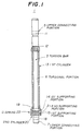
- FIG.1 shows a torsion bar device of the first embodiment of the present invention.
- FIG.2 shows a power steering system to which the torsion bar device in FIG.1 is applied.
- a power steering system 2 comprises an input shaft 4, a torsion bar device 1, and an output shaft 16.
- the torsion bar device 1 comprises a torsion bar 3, and the top of the torsion bar 3 is connected to the input shaft 4 through a shaft 9.
- the input shaft 4 is associated with a steering wheel (not shown) which is turned by a vehicle operator.
- the shaft 9 is connected to the input shaft 4, and the torsion bar 3 and the shaft 9 are coupled to each other by a pin 10.
- the torsion bar 3 comprises an upper connecting portion 5, a lower connecting portion 7, and a torsional portion 6 between the connecting portions 5 and 7.
- the upper connecting portion 5 has a transverse opening 11 in which the pin 10 is fitted.
- the torsional portion 6 is twisted when the steering wheel (not shown) is turned while the torsion bar 3 is subjected to a return force exerted by the tires (not shown) of the vehicle.
- the lower connecting portion 7 has a transverse opening 18 in which a pin 17 is fitted.
- the lower connecting portion 7 is secured to the output shaft 16 by the pin 17.
- the output shaft 16 is, for example, a pinion of the power steering system.
- the torsion bar 3 has a serrated portion 12 between the upper connecting portion 5 and the torsional portion 6, and a serrated portion 19 on the lower connecting portion 7.
- a first cylinder 13 is connected at its top with the serrated portion 12 of the torsion bar 3.
- This first cylinder 13 is a hollow member, and the inside diameter of the first cylinder 13 is slightly greater than the outside diameter of the torsional portion 6.
- the first cylinder 13 encompasses the torsional portion 6 of the torsion bar 3.
- the first cylinder 13 is formed with a set of first supporting portions 14 and 15 which outwardly project in the radial direction of the first cylinder 13.
- the bottom of the first cylinder 13 is attached to a second cylinder 20, and the second cylinder 20 is secured to the serrated portion 19 of the lower connecting portion 7 of the torsion bar 3.
- the second cylinder 20 is a hollow member, and the inside diameter of the second cylinder 20 is almost equal to the outside diameter of the lower connecting portion 7.
- the axial width of the second cylinder 20 is almost the same as the axial width of the serrated portion 19.
- the second cylinder 20 is secured to the serrated portion 19.
- the first cylinder 13 is connected to the lower connecting portion 7 of the torsion bar 3 through the connection of the serrated portion 19 and the second cylinder 20.
- the second cylinder 20 is formed with a second supporting portion 21 which outwardly projects in the radial direction of the second cylinder 20. As shown in FIG.1, the first cylinder 13 and the second cylinder 20 are connected to each other in a manner such that the first supporting portions 14 and 15 and the second supporting portion 21 are aligned in the longitudinal direction of the first cylinder 10.
- FIG.6 shows an assembly condition in which the first cylinder and the second cylinder are connected to each other.
- the first cylinder 13 is formed at its bottom portion with an inverted-L opening 13a.
- the second supporting portion 21 of the second cylinder 20 is loosely fitted in the opening 13a of the first cylinder 13, and the second supporting portion 21 is arranged between the first supporting portions 14 and 15.
- the torsion bar device 1 includes an elastic member, arranged on the first cylinder 13, for elastrically restoring the alignment of the first supporting portions 14 and 15 and the second supporting portion 21 by exerting a force in the circumferential direction of the torsion bar 3.
- the elastic member of this embodiment is a C-spring 22, and the C-spring 22 has a gap 22a in which the supporting portions 14, 15 and 21 are fitted by using the elastic compression force of the C-spring 22.
- the C-spring 22 biases the first and second supporting portions 14, 15 and 21 so as to regain the original neutral position after the steering wheel is turned by a vehicle operator.
- the adjusting operation to align the first and second supporting portions 14, 15 and 21 in the longitudinal direction of the first cylinder 13 can be easily performed by rotating the first cylinder 13 relative to the serrated portion 12 and rotating the second cylinder 20 relative to the serrated portion 19 in the circumferential direction of the first cylinder 13.
- FIG.7 shows an assembly condition in which the first cylinder and the second cylinder are connected to each other.
- the assembly condition shown in FIG.7 there is a rotational difference angle between the circumferential positions of the first supporting portions 14, 15 and the circumferential position of the second supporting portion 21. If the torsion bar device after the first and second cylinders are attached to the torsion bar is in the assembly condition shown in FIG.7, the supporting portions 14, 15 and 21 may be cut along the dotted lines in FIG.7 so that the supporting portions 14, 15 and 21 are aligned along a longitudinal line of the first cylinder 20.
- FIGS.3A and 3B show assembly conditions in which the C-spring 22 is attached to the first cylinder 13 and the second cylinder 20.
- the first supporting portions 14 and 15 and the second supporting portion 21 are fitted into the gap 22a of the C-spring 22, and the supporting portions 14, 15 and 21 are elastically compressed by the C-spring 22 in circumferential directions indicated by arrows "A1" and "A2" in FIGS. 3A and 3B.
- the compression force of the C-spring 22 acts on the torsion bar 3 to regain the original neutral position of the steering wheel when it is turned.
- FIG.3A shows the assembly condition in which the C-spring 22 is attached to the first cylinder 13 and the second cylinder 20 with the input shaft 4 and the output shaft 16 having no rotational difference angle.
- the supporting portions 14, 15 and 21 are aligned along a longitudinal line of the first cylinder 20.
- the input shaft 4 and the output shaft 16 have a rotational difference angle.
- the upper connecting portion 5 associated with the input shaft 4 is moved relative to the lower connecting portion 7 associated with the output shaft 16, the torsion bar 3 is twisted.
- the first cylinder 13 connected to the upper connecting portion 5 and the second cylinder 20 connected to the lower connecting portion 7 also have a rotational difference angle.
- FIG.3B shows the assembly condition in which the first cylinder 13 and the second cylinder 20 have a rotational difference angle when the steering wheel is turned.
- the first supporting portions 14 and 15 of the first cylinder 13 are moved in the circumferential direction "B1" and the second supporting portion 21 of the second cylinder 20 is moved in the circumferential direction "B2".
- the first supporting portions 14 and 15 and the second supporting portion 21 move apart from each other.
- the gap 22a of the C-spring 22 is widened by the first and second supporting portions 14, 15 and 21 in the circumferential direction.
- the first and second supporting portions 14, 15 and 21 are thus subjected to the compression force of the C-spring 22.
- the compression force of the C-spring 22 at this time acts on the torsion bar 3 to regain the original neutral position of the steering wheel.
- FIG.4 shows the torque characteristic of the torsion bar device indicating the relationship between the difference angle and the required torque.
- the difference angle is a rotational difference angle between the input shaft 4 and the output shaft 16 with respect to the circumferential direction.
- the overall torque characteristic of the torsion bar device of the present invention is indicated by a solid line in FIG.4.
- the torque characteristic of the torsion bar alone is indicated by a dotted line in FIG.4.
- the torque characteristic of the C-spring is indicated by a dotted chain line in FIG.4.
- the torque characteristic of the torsion bar device of the present invention in FIG.4 is equivalent to the resultant torque of the required torque of the torsion bar 3 and the required torque of the C-spring 22.
- the torque characteristic of the torsion bar 3 is a linear relationship between the difference angle and the required torque.
- the required torque of the torsion bar device 1 of the present invention corresponding to the difference angle around the original neutral position of the steering wheel, can be increased relative to that of the torsion bar 3 as indicated in FIG.4.
- the rigidity (or the spring constant) of the torsion bar device of the present invention when the steering wheel is around its original neutral position is increased, and it becomes possible for the torsion bar device to increase the stability and operability of the steering wheel.
- the rigidity of the torsion bar device when the steering wheel is around its original neutral position is determined based on the rigidity of the C-spring 22 and the rigidity of the first and second cylinders 13 and 20.
- the rigidity of the torsion bar device according to the present invention can be suitably increased.
- the torsion bar device 1 of the present invention is installed in the power steering system 2 shown in FIG.2.
- a rotary valve 8 is connected to a vane pump, a reservoir tank and a power cylinder.
- the parts of the power steering system 2, except for the rotary valve 8, are not shown in FIG.2.
- the torsion bar 3 having the same function as the conventional torsion bar is connected to the input shaft 4 via the shaft 9.
- the upper connecting portion 5 is secured to the shaft 9 by the pin 10.
- the power connecting portion 7 is secured to the output shaft 16 by the pin 17.
- the rotary valve 8 and the shaft 9 have a rotational difference angle corresponding to the rotational difference between the input shaft 4 and the output shaft 16.
- the rotary valve 8 changes the oil passage in accordance with the rotational difference angle.
- the operating pressure oil is selectively supplied to either the right chamber or the left chamber of the power cylinder so that the tie rod, connected to the tires, is power-assisted by the operating pressure oil.
- the operation of these parts 13, 20 and 22 is not related to the operation of the input shaft 4 and the output shaft 16.
- the torsion bar device 1 of the present invention it is possible to biase the first cylinder 13 and the second cylinder 20 for regaining the original neutral position of the steering wheel.
- the rigidity of the torsion bar device when the steering wheel is around its original neutral position can be increased in the torsion bar device 1 of the present invention.
- the structure of the torsion bar device of the present invention is simple and needs no modification of the other parts related to the power steering system.
- the structure of the power steering system in which the torsion bar device is incorporated can be made simple, and the productivity and cost performance thereof can be remarkably increased.
- the C-spring 22 is used as the elastic member of the torsion bar device for elastrically restoring the alignment of the first and second supporting portions 14, 15 and 21 along the longitudinal direction of the first cylinder 13.
- FIG.5 shows a torsion coil spring as a modification of the elastic member of the torsion bar device, and this torsion coil spring 23 in FIG.5 may be used instead.
- the first and second supporting portions 14, 15 and 21 are fitted in a snapping portion of the torsion coil spring 23, and the first and second supporting portions 14, 15 and 21 are retained by using the compression force of the torsion coil spring 23.
- FIG.8 shows the supporting portions 14, 15 and 21 of the torsion bar device of the first embodiment.
- FIGS.9A and 9B show the cross-sections of the torsion bar device taken along a line X-X in FIG.8, which line is located near the supporting portions 14, 15 and 21.
- the torsion bar 3 is simply accommodated in the first cylinder 3, and the inside diameter of the first cylinder 3 is slightly greater than the outside diameter of the torsion bar 3.
- the torsion bar device 1 has a clearance space 24 between the torsion bar 3 and the first cylinder 13 around the supporting portions 14, 15 and 21 to ensure the twisting deformation of the torsion bar 3.
- the C-spring 22 is expanded in the circumferential direction through the connection of the first cylinder 13 and the second cylinder 20.
- the torsion bar device 1 has merely the clearance space 24 between the first cylinder 13 and the torsion bar 3
- the first cylinder 13 is horizontally moved relative to the torsion bar 3 due to the reaction force from the C-spring 22.
- the supporting portions 14, 15 and 21 at this time will become the center around which the first cylinder 13 is horizontally moved relative to the torsion bar 3.
- FIG.9A shows the directions "A1" and "A2" of the movement of the first cylinder 13 wherein the first cylinder 13 is horizontally moved within the clearance space 24 relative to the torsion bar 3 in either direction.
- FIG.9B shows a condition in which the first cylinder 13 is moved in the direction "A1" relative to the torsion bar 3.
- the torsion bar device of the first embodiment has a problem in that the first cylinder 13 may be moved relative to the torsion bar 3 when the torsion bar 3 is twisted and the C-spring is expanded. If the first cylinder 13 is brought into contact with either the C-spring 22 or the torsion bar 3 by such a movement, the rigidity of the torsion bar 3 and the C-spring 22 varies considerably. Therefore, the torsion bar device of the first embodiment at this time may not stably regain the original neutral position of the steering wheel, and the rigidity of the torsion bar device when the steering wheel is around the neutral position is relatively low.
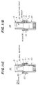
- FIG.10 shows a torsion bar device 30 of the second embodiment of the present invention.
- FIG.11A shows the detailed structure of the torsion bar device in FIG.10 in the vicinity of the first and second supporting portions.
- FIGS.10 and 11A-11D the parts which are the same as corresponding parts in FIGS.1 and 3A-3B are designated by the same reference numerals, and a description thereof will be omitted.
- the torsion bar device 30, shown in FIGS.10 and 11A, has a bushing 31 provided in the clearance space 24 between the first cylinder 13 and the torsion bar 3 near the first and second supporting portions 14, 15 and 21.
- the bushing 31 is made of a hard metal material with a suitable abrasion resistance.
- the bushing 31 is attached to the torsion bar device 30 by fitting it between the inside wall of the first cylinder 13 and the outside wall of the torsion bar 3 near the first supporting portion 14. It should be noted that the torsion bar 3 is rotatably supported by the bushing 31 while the bushing 31 is fitted between the first cylinder 13 and the torsion bar 3.
- the bushing 31 is provided in the clearance space 24 between the first cylinder 13 and the torsion bar 3 near the first and second supporting portions 14, 15 and 21.
- the first cylinder 13 is connected to the torsion bar 3 via the bushing 31, and it is rotatably supported by the bushing 31.
- the torsion bar 3 is twisted and the C-spring 22 is expanded due to the turning of the steering wheel, it is likely that the first cylinder 13 is horizontally moved relative to the torsion bar 3 in the direction "A1" or "A2" as indicated in FIG.9A.
- the torsion bar device 30 has the bushing 31 in the clearance space 24 between the first cylinder 13 and the torsion bar 3, the bushing 31 at this time prevents the first cylinder 13 from being horizontally moved relative to the torsion bar 3.
- a restricting member (or the bushing 31) is provided for restricting the undesired horizontal movement of the first cylinder 13 relative to the torsion bar 3 when the torsion bar 3 is twisted and the C-spring 22 is expanded. It is thus possible for the torsion bar device of the second embodiment to more stably regain the original neutral position of the steering wheel, and the rigidity of the torsion bar device when the steering wheel is around its original neutral position can be remarkably increased.
- FIG.11B shows a modification of the torsion bar device of the second embodiment in FIG.10.
- the first cylinder 13 is formed with a bearing portion 33 near the first supporting portion 14, and no clearance between the first cylinder 13 and the torsion bar 3 is formed.
- the torsion bar device 32 in the assembled condition has the torsion bar 3 rotatably supported by the bearing portion 33.
- the first cylinder 13 is formed with the bearing portion 33, and the torsion bar 3 is rotatably supported by the bearing portion 33.
- the first cylinder 13 is directly in contact with the torsion bar 3 via the bearing portion 33. Accordingly, when the torsion bar 3 is twisted and the C-spring 22 is expanded, the bearing portion 33 prevents the first cylinder 13 from being horizontally moved relative to the torsion bar 3. It is thus possible to stably regain the original neutral position of the steering wheel, and the rigidity of the torsion bar device when the steering wheel is around its original neutral position can be increased.
- FIG.11C shows another modification of the torsion bar device of the second embodiment in FIG.10.
- a ball bearing 35 is provided between the first cylinder 13 and the torsion bar 3 near the first supporting portion 14, and no clearance between the first cylinder 13 and the torsion bar 3 is formed there.
- One of two methods for attaching the ball bearing 35 to the torsion bar device 34 is selectable. One method is to press-fit the ball bearing 35 in the first cylinder 13, and then arrange the first cylinder 13 having the ball bearing 35 onto the torsion bar 3. The other method is to press-fit the ball bearing 35 onto the torsion bar 3, and then place the torsion bar 3 having the ball bearing 35 into the first cylinder 13.
- the ball bearing 35 is provided between the first cylinder 13 and the torsion bar 3 in the vicinity of the first supporting portion 14, and the torsion bar 3 is rotatably supported by the ball bearing 35. Accordingly, when the torsion bar 3 is twisted and the C-spring 22 is expanded, the ball bearing 35 prevents the first cylinder 13 from being horizontally moved relative to the torsion bar 3. It is thus possible to stably regain the original neutral position of the steering wheel, and a high rigidity of the torsion bar device when the steering wheel is around the neutral position can be maintained. Also, the sliding friction between the first cylinder 13 and the torsion bar 3 can be suitably reduced by the ball bearing 35, and the sensitivity of the power steering system to the vehicle operator can be increased by means of the torsion bar device 34.
- a known needle bearing may be provided between the first cylinder 13 and the torsion bar 3 instead of the ball bearing 35.
- FIG.11D shows another modification of the torsion bar device of the second embodiment in FIG.10.
- a resin portion 36 is provided between the first cylinder 13 and the torsion bar 3 near the first supporting portion 14, and no clearance between the first cylinder 13 and the torsion bar 3 is formed there.
- the first cylinder 13 is formed with an injection hole 37 near the first supporting portion 14.
- the resin portion 36 is formed by injecting resin from the injection hole 37 into a space between the first cylinder 13 and the torsion bar 3 after the first cylinder 13 is attached to the torsion bar 3.
- the first cylinder 13 is separated from the resin portion 36 while the torsion bar 3 and the resin portion 36 are attached to each other, so that the first cylinder 13 is rotatably supported by the resin portion 36.
- the torsion bar 3 is separated from the resin portion 36 while the first cylinder 13 and the resin portion 36 are attached, so that the first cylinder 13 is rotatably supported by the resin portion 36.
- the resin portion 36 is formed between the first cylinder 13 and the torsion bar 3 in the vicinity of the first supporting portion 14.
- the resin portion 36 prevents the first cylinder 13 from being horizontally moved relative to the torsion bar 3. It is thus possible to stably regain the original neutral position of the steering wheel, and the rigidity of the torsion bar device when the steering wheel is around its original neutral position can be increased.
- the torsion bar device of the second embodiment it is not necessary to provide the bushing 31, the bearing portion 33 or the resin portion 36 throughout all the periphery of the torsion bar 3. It is sufficient to place one of the bushing 31, the bearing portion 33 and the resin portion 36 at two opposing peripheral portions of the first cylinder 13 only, so that it prevents the movement of the first cylinder 13 in the directions "A1" and "A2" in FIG.9A.
- FIG.12A shows a torsion bar device 40 of the third embodiment of the present invention, and it is partially cut away to show the first and second supporting portions of one pre-load unit of the torsion bar device 40.
- FIG.12B shows a cross section of the torsion bar device 40 of the third embodiment taken along a line X-X in FIG.12A.
- the parts which are the same as corresponding parts in FIGS.1 and 3A-3B are designated by the same reference numerals, and a description thereof will be omitted.
- the torsion bar devices of the first and second embodiments have a single pre-load unit including the first and second supporting portions 14, 15 and 21, and the C-spring 22.
- the torsion bar device 40 of the third embodiment shown in FIGS.12A and 12B, has three pre-load units 41-1, 41-2 and 41-3 each of which includes the first and second supporting portions and the C-spring.
- the three pre-load units are arranged in a column on the first cylinder 13 near the enlarged second cylinder 20.
- the pre-load unit 41-1 includes first supporting portions 14-1 and 15-1, a second supporting portion 21-1, and a C-spring 22-1, and these parts are not shown in FIG.12A.
- the pre-load unit 41-2 includes first supporting portions 14-2 and 15-2, a second supporting portion 21-2, and a C-spring 22-2.
- the pre-load unit 41-3 includes first supporting portions 14-3 and 15-3, a second supporting portion 21-3, and a C-spring 22-3.
- the respective supporting portions of the three pre-load units 41-1 through 41-3 are uniformly arranged on the circumference of the torsion bar 3, and the rotational difference angle between the second supporting portions of two neighboring pre-load units when the steering wheel is at its original neutral position is equal to 120°.
- the first cylinder 13 of the third embodiment is formed with the first supporting portions 14-1 through 14-3 and 15-1 through 15-3, and that the second cylinder 20 is formed with the second supporting portions 21-1 through 21-3.
- the reaction forces from the C-springs act on the first cylinder 13 so as to horizontally move the first cylinder 13 relative to the torsion bar 3.
- the respective supporting portions of the three pre-load units are uniformly arranged on the circumference of the torsion bar 3, and the respective reaction forces from the C-springs are canceled by each other and the reaction forces are in equilibrium. It is thus possible for the plurality of the pre-load units 41-1 through 41-3 to stably prevent the first cylinder 13 from being horizontally moved relative to the torsion bar 3 when the torsion bar 3 is twisted due to the turning of the steering wheel. Also, it is possible for the torsion bar device 40 of the third embodiment to stably prevent the first cylinder 13 from coming in contact with the torsion bar 3 or the C-springs when the steering wheel is turned.
- the rigidity of the torsion bar device 40 of the third embodiment can be suitably increased by selecting an appropriate mechanical strength of the first and second cylinders 13 and 20 and the C-springs 22-1 through 22-3. Also, the rigidity of the torsion bar device 40 when the steering wheel is around its original neutral position is further increased by using the plurality of the pre-load units.
- the C-spring 22 is used as the elastic member of the torsion bar device of the present invention.
- the following description relates to a few modifications of the elastic member according to the present invention.
- FIG.13A shows a pair of flat springs 43 and 44 as a modification of the elastic member.
- the flat springs 43 and 44 are made of spring steel with a suitable mechanical strength. Both ends of the respective flat springs 43 and 44 are fixed onto the first cylinder 13 by welding. The welded portions of the flat springs 43 and 44 are indicated by shading lines in FIG.13A.
- the first supporting portions 14 and 15 of the first cylinder 13 and the second supporting portion 21 of the second cylinder 20 are fitted on the inward-facing walls of both the flat springs 43 and 44.
- the first cylinder 13 is formed with a slot 45, and the second supporting portion 21 is inserted in the slot 45 and it outwardly projects from the first cylinder 13.
- the second supporting portion 21 is movable in the circumferential direction of the second cylinder 20 within the range of the slot 45.
- the flat springs 43 and 44 retain the first and second supporting portions 14, 15 and 21 against the inward-facing walls of the flat springs, so as to regain the original neutral position when the steering wheel is turned.
- the flat springs 43 and 44 can be installed on the first cylinder 13 of the torsion bar device more easily than the C-spring 22 described above. Also, as the flat springs are less expensive than the C-springs, the cost of the parts for the torsion bar device can be reduced by using the flat springs 43 and 44.
- FIG.13B shows a pair of flat springs 46 and 47 as another modification of the elastic member.
- the flat springs 46 and 47 are fixed onto the first cylinder 13 by using pins or rivets.
- the flat spring 46 is formed at its ends with holes 46a and 46b, and the flat spring 47 is formed at its ends with holes 47a and 47b.
- the pins or rivets are inserted in these holes, and the flat springs 46 and 47 are fixed onto the first cylinder 13 by the pins or rivets.
- the first and second supporting portions 14, 15 and 21 are fitted on the inward-facing walls of the flat springs 46 and 47.
- the first cylinder 13 is formed with the slot 45.
- the second supporting portion 21 is inserted in the slot 45 and it outwardly projects from the first cylinder 13.
- the second supporting portion 21 is movable in the circumferential direction of the second cylinder 20 within the range of the slot 45.
- the flat springs 46 and 47 can be installed on the first cylinder 13 of the torsion bar device more easily than the C-spring 22 described above. Also, the elastic member shown in FIG.13B does not require welding equipment needed for welding the flat springs 43 and 44 to the torsion bar device. Also, as the flat springs are less expensive than the C-springs, the cost of the parts of the torsion bar device can be reduced by using the flat springs 46 and 47.
- FIGS.14A and 14B show a torsion spring 48 as a different modification of the elastic member.
- the torsion spring 48 is made of spring steel with a suitable mechanical strength.
- One end of the torsion spring 48 is fixed onto the first cylinder 13 by welding, and the welded portion is indicated by shading lines in FIGS.14A and 14B.
- the torsion spring 48 is formed at its center portion with a gap 49, and the torsion spring 48 has a pair of arm portions 48a and 48b separated by the gap 49.
- the arm portions 48a and 48b downwardly extend from the bottom of the first cylinder 13, and the arm portions 48a and 48b have rounded ends at the leading edges.
- the first cylinder 13 is formed at its bottom portion with a pair of stoppers 50a and 50b.
- the stoppers 50a and 50b are arranged on both sides of the torsion spring 48, and the end portions of the stoppers 50a and 50b are opposed to each other and they face the sides of the arm portions 48a and 48b in the opposite directions.
- the movements of the arm portions 48a and 48b in the circumferential direction of the torsion bar 3 are restricted by the stoppers 50a and 50b.
- the second cylinder 20 is formed at its upper portion with a recess 51.
- the rounded ends of the arm portions 48a and 48b of the torsion bar 48 are brought into contact with the inside walls of the recess 51.
- the recess 51 has inside walls 51a and 51b.
- the rounded end of the arm portion 48a comes in contact with the inside wall 51a of the recess 51, and the rounded end of the arm portion 48b comes in contact with the inside wall 51b of the recess 51, as shown in FIG.14A.
- the first cylinder 13 is also moved in the direction "B2" relative to the second cylinder 20, while the second cylinder 20 remains at its original position.
- the arm portion 48a of the torsion spring 48 is pressed by the inside wall 51a of the recess 51 in the direction "B1" so that the arm portion 48a is elastically deformed.
- the arm portion 48b of the torsion spring 48 is pressed by the stopper 50b in the direction "B2" so that the arm portion 48b is elastically deformed.
- the first cylinder 13 and the second cylinder 20 are biased by the torsion spring 48 so as to regain the original neutral position of the steering wheel.
- the welded portions of the torsion spring 48 constitute the first supporting portions of the torsion bar device of the present invention, and the recess 51 of the second cylinder 20 constitutes the second supporting portion of the present invention.
- the torsion spring 48 can be installed on the first cylinder 13 more easily than the C-spring 22 described above. Also, as the torsion springs are less expensive than the C-springs, the cost of the parts for the torsion bar device can be reduced by using the torsion spring 48.
- FIGS.15 through 22 the parts which are the same as corresponding parts of the above described embodiments are designated by the same reference numerals and a description thereof will be omitted.
- FIG.15 shows a first supporting portion 55 as a modification of the first supporting portions 14 and 15 of the first cylinder 13.
- the first supporting portions 14 and 15 of the first cylinder 13 are separately formed.
- the first supporting portion 55 shown in FIG.15 is formed into a single portion, but it includes a bridge portion 55a which is outwardly bulged.
- the second supporting portion 21 of the second cylinder 20 is surrounded by the bridge portion 55a. Thus, the second supporting portion 21 does not come into contact with the first supporting portion 55 even when the torsion bar 3 is twisted.
- FIGS.16A through 16B show a method of forming the first supporting portion 55 of the first cylinder 13 in FIG.15.
- a wall portion of the first cylinder 13, corresponding in position to the second supporting portion 21 of the second cylinder 20, is plastically deformed by using a jig so as to form the outwardly bulged bridge portion 55a.
- the plastic deformation of the first cylinder 13 for forming the first supporting portion 55 with the bridge portion 55a is indicated by an arrow in FIG.16A.
- the rigidity of the first cylinder 13 with the first supporting portion 55 is higher than that of the first cylinder 13 with the first supporting portions 14 and 15 in the above described embodiments.
- the first supporting portion 55 thus formed is rigid enough, and it is unlikely that it is easily bent or damaged in practical use over a long term.
- the reliability of the torsion bar device can be increased by using the first cylinder 13 having the first supporting portion 55.
- FIGS.17A through 17D show a method of forming the first supporting portions of the first cylinder of the first through third embodiments described above.
- a pipe member 56 is pressed against a flat jig 57 so that the pipe member 56 is plastically deformed to form the end of the pipe member 56 into a flared portion 58.
- the unnecessary portion (indicated by a two-dot chain line in FIGS.17B and 17C) is removed from the flared portion 58 of the pipe member 56 by punching or cutting.
- the first supporting portion 15 of the first cylinder 13 is formed as shown in FIGS.17B and 17C.
- the first supporting portion 14 of the first cylinder 13 is formed by performing the punching and plastic deformation in the direction indicated by an arrow in FIG.17D. Accordingly, the first cylinder 13 with the first supporting portions 14 and 15 can be formed.
- the first cylinder 13 having the first supporting portions 14 and 15 can be easily produced because the plastic working of pipe members can be easily performed.
- FIGS.18A and 18B show another method of forming the first supporting portions 14 and 15 of the first cylinder 13 of the above described embodiments.
- the wall of the first cylinder 13 is punched along a horizontal line in the middle between the locations corresponding to the first supporting portions 14 and 15, so that the first supporting portions 14 and 15 are formed at a time.
- the first supporting portions 14 and 15 can be very simply and efficiently produced.
- the punched portions of the first cylinder corresponding to the first supporting portions 14 and 15 may have rough edges, or the punched portions may deviate from each other in the horizontal direction of the first cylinder 13.
- the grinding or cutting operation is performed for the first cylinder 13 after the wall thereof is punched along the middle line.
- the punched portions are ground or cut along a line at a given horizontal distance (indicated by a one-dot chain line in FIG.18B) so that the first supporting portions 14 and 15 have smooth edges and the same distance from the axial line of the first cylinder 13 as shown in FIG.18B.
- FIG.19 shows a different method of forming the first supporting portions 14 and 15 of the first cylinder 13 of the above described embodiments.
- the first cylinder 13 is formed with two press-in holes 60 and 61 at the locations corresponding to the first supporting portions 14 and 15, and pins 62 and 63 are press-fitted in the holes 60 and 61 so as to form the first supporting portions 14 and 15. Since the forming of the press-in holes 60 and 61 and the fitting of the pins 62 and 63 in the holes 60 and 61 are easily performed, the first supporting portions 14 and 15 of the first cylinder 13 can be easily and efficiently formed.
- the opening 13a of the first cylinder 13 in which the second supporting portion 21 is loosely fitted as shown in FIG.6 may be formed at the same time as the press-in holes 60 and 61 are formed, or after the pins 62 and 63 are fitted in the holes 60 and 61.
- FIG.19 shows the condition of the first cylinder 13 before the opening 13a of the first cylinder 13 is formed.
- the pins 62 and 63 may be welded to the first cylinder after the press-fitting of the pins into the holes 60 and 61.
- FIG.20 shows a further different method of forming the first supporting portions 14 and 15 of the above described embodiments.
- the burring operation of the first cylinder 13 is performed by using a punch 64 from the inside of the first cylinder 13, so that the first supporting portions 14 and 15 are formed on the first cylinder 13 at the same time by the burring operation. Since the first supporting portions 14 and 15 of the first cylinder 13 is formed by a single burring operation, the forming of the first supporting portions 14 and 15 can be easily and efficiently accomplished by using the forming method shown in FIG.20.
- the opening 13a of the first cylinder, in which the second supporting portion 21 is loosely fitted as shown in FIG.6, may be formed before or after the first supporting portions 14 and 15 are formed by using the forming method in FIG.20.
- FIG.20 shows the condition of the first cylinder 13 before the opening 13a of the first cylinder 13 is formed.
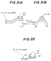
- FIGS.21A and 21B show a further different method of forming the first supporting portions 14 and 15 of the above described embodiments.
- a welding material is welded to the first cylinder 13 at the locations corresponding to the first supporting portions 14 and 15.
- the excess metal of the welding material indicated by a two-dot chain line in FIG.21B is removed by cutting, at the same as the opening 13a of the first cylinder 13 shown in FIG.21A is formed.
- the first supporting portions 14 and 15 of the first cylinder 13 are formed in this manner. Since the welding operation in the forming method shown in FIGS.21A and 21B can be automatically performed in the assembly line, the first supporting portions 14 and 15 of the first cylinder 13 can be easily and efficiently formed.
- FIG.22 shows a further different method of forming the first supporting portions 14 and 15 of the above described embodiments.
- pins 65 and 66 are welded to the first cylinder 13 at the locations corresponding to the first supporting portions 14 and 15 so that the first supporting portions 14 and 15 are formed.
- the first supporting portions 14 and 15 of the first cylinder 13 can be easily formed.
- the torsion bar 3 and the first cylinder 13 are connected to each other by the serrated portion 12, and the torsion bar 3 and the second cylinder 20 are connected to each other by the serrated portion 19.
- the serrated portions 12 and 19 of the torsion bar device by which the torsion bar 3 and the first cylinder 13 are connected and by which the torsion bar 3 and the second cylinder 20 are connected, are vital to the safety of the power steering system.
- the serrrated portions must be accurately formed and firmly connected to the first and second cylinders 13 and 20 and must be straight in the longitudinal direction of the torsion bar 3.
- the torsion bar 3 slides in the circumferential direction in relation to the first cylinder 13 or the second cylinder 20 when the steering wheel is turned, one cannot safely and stably operate the steering system. Also, if the first and second cylinders 13 and 20 are not correctly aligned with the torsion bar 3, it is difficult to safely and stably operate the steering system. Therefore, the joining method of the first cylinder and the torsion bar and the joining method of the second cylinder and the torsion bar are very important to the torsion bar device of the present invention.
- FIG.23A shows a tapered serration 67 of the torsion bar 3 by which the first cylinder 13 and the torsion bar 3 are connected, instead of the serrated portion 12 in the above described embodiments.
- the tapered serration 67 of the torsion bar 3 in FIG.23A has an outside diameter that is gradually increased along an insertion line (indicated by an arrow in FIG.23A) of the first cylinder 13 in the longitudinal direction of the torsion bar 3.
- the tapered serration 67 in FIG.23A By using the tapered serration 67 in FIG.23A, the leading edge of the first cylinder 13 is smoothly inserted into the tapered serration 67, so that the first cylinder 13 can be easily and accurately connected to the torsion bar 3.
- the tapered serration 67 it is possible to prevent the first cylinder 13 from being connected to the torsion bar 3 in a misaligned manner.
- FIG.23B shows a barrel-shaped serration 68 of the torsion bar 3 by which the first cylinder 13 and the torsion bar 3 are connected as a modification of the above described embodiments.
- the serration 68 of the torsion bar 3 in FIG.23B has a barrel-shaped cross-section and has an outside diameter that varies along the longitudinal direction of the torsion bar 3, that is, it is greatest in the middle of the serration 68 and smallest at the upper and lower ends thereof as shown in FIG.23B.
- FIG.23C shows a serration 69 of the torsion bar 3 by which the first cylinder 13 and the torsion bar 3 are connected as a modification of the above described embodiments.
- the serration 69 of the torsion bar 3 in FIG.23C is provided with a guide portion 70 through which the leading edge of the first cylinder 13 is inserted into the serration 69.
- An aligning operation may be easily performed when the first cylinder 13 is inserted in the guide portion 70, so as to adjust the alignment between the torsion bar 3 and the first cylinder 13 .
- it is possible to accurately connect the torsion bar 3 and the first cylinder 13 together. It is possible to prevent the first cylinder 13 from being incorrectly aligned with the torsion bar 3.
- FIGS.24A through 24C show various methods of joining the torsion bar 3 and the first cylinder 13 without using a serration. By the same joining method described here, the torsion bar 3 and the second cylinder 20 may be joined together.
- FIG.24A shows a connecting pin 71 by which the first cylinder 13 and the torsion bar 3 are joined together.
- the connecting pin 71 in FIG.24A it is possible to stably prevent the first cylinder 13 from sliding relative to the torsion bar 3 in the circumferential direction when the steering wheel is turned.
- the connecting pins is less expensive than using the serrated portions 12 and 19, the cost of the parts of the torsion bar device can be reduced by using the connecting pin 71.
- FIG.24B shows staked portions 72 by which the first cylinder 13 and the torsion bar 3 are joined together.
- the staked portions 72 in FIG.24B it is possible to easily and stably join the first cylinder 13 and the torsion bar 3.
- the cost of the parts of the torsion bar device can be reduced by using the staked portions 72.
- FIG.24C shows welded portions 73 by which the first cylinder 13 and the torsion bar 3 are joined together.
- the welded portions 73 in FIG.24C it is possible to stably prevent the first cylinder 13 from sliding relative to the torsion bar 3 in the circumferential direction when the steering wheel is turned. Also, it is possible to easily and stably join the first cylinder 13 and the torsion bar 3.
- the second cylinder 20 is connected to the serrated portion 19 of the lower connecting portion 7 of the torsion bar 3, and the first cylinder 13 is connected to the serrated portion 12 below the upper connecting portion 5.
- the methods of connecting the second cylinder 20 and the torsion bar 3 and of connecting the first cylinder 13 and the torsion bar 3 according to the present invention are not limited to these embodiments. Those skilled in the art may recognize as a matter of course that the second cylinder 20 can be connected to the upper connecting portion 5 while the first cylinder 13 can be connected to the lower connecting portion 7 in the torsion bar device of the present invention.
- the structure of the torsion bar device of the present invention is simple and needs no modification of the other parts related to the power steering system.
- the structure of the power steering system in which the torsion bar device is incorporated can be made simple, and the productivity and cost performance thereof can be remarkably increased.
- a restricting member is provided, in the clearance space between the torsion bar and the first cylinder, for restricting the horizontal movement of the first cylinder 13 relative to the torsion bar 3 when the torsion bar 3 is twisted due to the turning of the steering wheel. It is thus possible for the torsion bar device of the present invention to very stably regain the original neutral position of the steering wheel. The rigidity of the torsion bar device when the steering wheel is around its original neutral position can be remarkably increased.
- a plurality of pre-load units each of which includes the first supporting portions, the second supporting portion and the elastic member are arranged such that the respective first and second supporting portions of the pre-load units are uniformly arranged on the circumference of the torsion bar 3.
- a torsion bar device includes a torsion bar (3) having a torsional portion (6), an upper connecting portion (5) associated with an input shaft, and a lower connecting portion (7) associated with an output shaft; a first cylinder (13) for encompassing the torsional portion, one end of the first cylinder being connected to one of the upper and lower connecting portions, and the other end of the first cylinder extending in the longitudinal direction of the torsion bar to the other connecting portion of the torsion bar; a second cylinder (20) for encompassing and being connected to the other one of the upper and lower connecting portions of the torsion bar; a first supporting member (14, 15) for supporting the torsion bar at the other end of the first cylinder in a circumferential direction of the torsion bar; a second supporting member (21) for supporting the torsion bar in the circumferential direction at a portion of the second cylinder where the second supporting member is aligned with the first supporting member; and an elastic member (22) for elastically restoring the alignment of the first and second supporting members by
Landscapes
- Engineering & Computer Science (AREA)
- Chemical & Material Sciences (AREA)
- Combustion & Propulsion (AREA)
- Transportation (AREA)
- Mechanical Engineering (AREA)
- Springs (AREA)
- Power Steering Mechanism (AREA)
Applications Claiming Priority (4)
| Application Number | Priority Date | Filing Date | Title |
|---|---|---|---|
| JP96085/93 | 1993-04-22 | ||
| JP9608593 | 1993-04-22 | ||
| JP6006240A JPH072125A (ja) | 1993-04-22 | 1994-01-25 | パワーステアリング用トーションバー |
| JP6240/94 | 1994-01-25 |
Publications (2)
| Publication Number | Publication Date |
|---|---|
| EP0621168A1 true EP0621168A1 (de) | 1994-10-26 |
| EP0621168B1 EP0621168B1 (de) | 1999-02-03 |
Family
ID=26340327
Family Applications (1)
| Application Number | Title | Priority Date | Filing Date |
|---|---|---|---|
| EP94106125A Expired - Lifetime EP0621168B1 (de) | 1993-04-22 | 1994-04-20 | Torsionsstabvorrichtung für ein Servolenksystem |
Country Status (4)
| Country | Link |
|---|---|
| US (1) | US5478059A (de) |
| EP (1) | EP0621168B1 (de) |
| JP (1) | JPH072125A (de) |
| DE (1) | DE69416334T2 (de) |
Cited By (3)
| Publication number | Priority date | Publication date | Assignee | Title |
|---|---|---|---|---|
| US5649467A (en) * | 1996-02-28 | 1997-07-22 | Trw Inc. | Power steering control valve |
| US5851006A (en) * | 1995-06-12 | 1998-12-22 | Trw Fahrwerksysteme Gmbh & Co. Kg | Torsional element for steering valves and spring characteristic improving process |
| WO2015028122A1 (de) * | 2013-08-27 | 2015-03-05 | Thyssenkrupp Presta Ag | Lenkwelle für eine kraftfahrzeuglenkung |
Families Citing this family (11)
| Publication number | Priority date | Publication date | Assignee | Title |
|---|---|---|---|---|
| DE4404535C2 (de) * | 1994-02-12 | 2000-07-27 | Trw Fahrwerksyst Gmbh & Co | Lenkventil |
| DE19615543C2 (de) * | 1996-04-19 | 1998-09-17 | Daimler Benz Ag | Servoventil |
| KR100239908B1 (ko) * | 1996-05-23 | 2000-01-15 | 요시다 도시오 | 래크 피니언식 동력 조향 장치 |
| US6070515A (en) * | 1998-11-23 | 2000-06-06 | Trw Inc. | Steering system |
| CN1789416B (zh) * | 2001-05-11 | 2011-11-16 | 协和发酵麒麟株式会社 | 含人抗体λ轻链基因的人类人工染色体 |
| DE202004011804U1 (de) * | 2004-07-28 | 2004-12-02 | Trw Automotive Gmbh | Hydraulisches Servolenkventil mit Lenkmomentüberlagerung |
| US7484759B2 (en) * | 2005-07-25 | 2009-02-03 | Delphi Technologies, Inc. | Vehicle power steering assembly and method for assembling the vehicle power steering assembly |
| JP5067787B2 (ja) * | 2007-02-06 | 2012-11-07 | Ntn株式会社 | インホイールモータ駆動装置 |
| US8549945B2 (en) * | 2008-11-12 | 2013-10-08 | Mando Corporation | Reducer of electronic power steering apparatus |
| DE102014101189B4 (de) * | 2014-01-31 | 2019-07-25 | Hs Products Engineering Gmbh | Kraftübertragungsvorrichtung für ein Getriebe und Montageverfahren |
| US9518627B2 (en) | 2014-11-26 | 2016-12-13 | Steering Solutions Ip Holding Corporation | Changes enabling the elimination of processes for a torsion bar |
Citations (4)
| Publication number | Priority date | Publication date | Assignee | Title |
|---|---|---|---|---|
| EP0038493A2 (de) * | 1980-04-17 | 1981-10-28 | Trw Inc. | Kraftlenkvorrichtung |
| WO1987002318A2 (en) * | 1985-10-21 | 1987-04-23 | Zahnradfabrik Friedrichshafen Ag | Centering device for two assemblies provided with counter-rotating parts |
| JPS62191269A (ja) * | 1986-02-17 | 1987-08-21 | Atsugi Motor Parts Co Ltd | 動力操向装置 |
| EP0290698A1 (de) * | 1987-05-12 | 1988-11-17 | Bendix Espana S.A. | Federnde Zentriervorrichtung und Totgang-Kupplung für zwei drehbewegliche Teile |
Family Cites Families (6)
| Publication number | Priority date | Publication date | Assignee | Title |
|---|---|---|---|---|
| US3371940A (en) * | 1966-06-15 | 1968-03-05 | Army Usa | Vehicle variable height suspension systems |
| FR2520460A1 (fr) * | 1982-01-27 | 1983-07-29 | Renault | Dispositif d'immobilisation d'un palier elastique dans un tube rigide |
| JPH0245109A (ja) * | 1988-08-05 | 1990-02-15 | Matsushita Electric Works Ltd | 基材へのワニス含浸方法 |
| JP2876129B2 (ja) * | 1988-10-22 | 1999-03-31 | 東洋ファルマー株式会社 | 7―カルボキシメトキシ―4―フェニルクマリン誘導体とその製法及び用途 |
| US5050443A (en) * | 1990-11-19 | 1991-09-24 | Ford Motor Company | Steering wheel return assist device |
| JP3044273B2 (ja) * | 1991-05-24 | 2000-05-22 | ビショップ ステアリング テクノロジー リミテッド | 動力操向装置の回転弁 |
-
1994
- 1994-01-25 JP JP6006240A patent/JPH072125A/ja active Pending
- 1994-04-05 US US08/222,922 patent/US5478059A/en not_active Expired - Fee Related
- 1994-04-20 DE DE69416334T patent/DE69416334T2/de not_active Expired - Fee Related
- 1994-04-20 EP EP94106125A patent/EP0621168B1/de not_active Expired - Lifetime
Patent Citations (4)
| Publication number | Priority date | Publication date | Assignee | Title |
|---|---|---|---|---|
| EP0038493A2 (de) * | 1980-04-17 | 1981-10-28 | Trw Inc. | Kraftlenkvorrichtung |
| WO1987002318A2 (en) * | 1985-10-21 | 1987-04-23 | Zahnradfabrik Friedrichshafen Ag | Centering device for two assemblies provided with counter-rotating parts |
| JPS62191269A (ja) * | 1986-02-17 | 1987-08-21 | Atsugi Motor Parts Co Ltd | 動力操向装置 |
| EP0290698A1 (de) * | 1987-05-12 | 1988-11-17 | Bendix Espana S.A. | Federnde Zentriervorrichtung und Totgang-Kupplung für zwei drehbewegliche Teile |
Non-Patent Citations (1)
| Title |
|---|
| PATENT ABSTRACTS OF JAPAN vol. 012, no. 039 (M - 665) 5 February 1988 (1988-02-05) * |
Cited By (4)
| Publication number | Priority date | Publication date | Assignee | Title |
|---|---|---|---|---|
| US5851006A (en) * | 1995-06-12 | 1998-12-22 | Trw Fahrwerksysteme Gmbh & Co. Kg | Torsional element for steering valves and spring characteristic improving process |
| US5649467A (en) * | 1996-02-28 | 1997-07-22 | Trw Inc. | Power steering control valve |
| WO2015028122A1 (de) * | 2013-08-27 | 2015-03-05 | Thyssenkrupp Presta Ag | Lenkwelle für eine kraftfahrzeuglenkung |
| CN105492298A (zh) * | 2013-08-27 | 2016-04-13 | 蒂森克虏伯普利斯坦股份公司 | 用于机动车辆转向系统的转向轴 |
Also Published As
| Publication number | Publication date |
|---|---|
| DE69416334T2 (de) | 1999-07-15 |
| DE69416334D1 (de) | 1999-03-18 |
| EP0621168B1 (de) | 1999-02-03 |
| US5478059A (en) | 1995-12-26 |
| JPH072125A (ja) | 1995-01-06 |
Similar Documents
| Publication | Publication Date | Title |
|---|---|---|
| US5478059A (en) | Power steering torsion bar biased to return to neutral | |
| KR101647858B1 (ko) | 중공 샤프트 결합 장치 | |
| US5983742A (en) | Rack and pinion steering device with split roller rack bar support | |
| KR102769271B1 (ko) | 스티어 바이 와이어식 조향장치 | |
| US4774847A (en) | Mechanism for centering relatively rotative components, particularly in rotary valves | |
| EP1056948B1 (de) | Kolbenpumpe | |
| WO2022053097A1 (de) | Riemenscheibenentkoppler mit an einem nabenbestandteil angebundenen trägerblech eines schwingungstilgers | |
| EP1460289B1 (de) | Konstruktion zur verbindung eines kugelgelenks mit einem arm | |
| DE102004013489B4 (de) | Radnabe und Verfahren zum Montieren eines Rads | |
| CN112621172A (zh) | 用于十字轴万向节的组装方法和组装装置 | |
| EP1878937B1 (de) | Elastisches Fahrwerkslager | |
| JPH08505336A (ja) | 特に舵取り弁の芯出し装置 | |
| US11807312B2 (en) | Power steering device | |
| US6267133B1 (en) | Method for mounting a steering valve with a centring unit | |
| KR20080019586A (ko) | 볼 조인트 | |
| KR100274863B1 (ko) | 파워스티어링 장치 | |
| JP4205682B2 (ja) | 弾性軸継手 | |
| JP2002211422A (ja) | トーションバーの組み付け方法およびその方法に用いるトーションバー | |
| US6244966B1 (en) | Torsionally-rigid compensating coupling | |
| DE102019118406A1 (de) | Geräuschoptimierte Lagereinheit für ein lenkhilfeunterstütztes Lenkgetriebe | |
| EP4556744B1 (de) | Elastisches lagerelement | |
| US6267144B1 (en) | Rotary disk valve for power steering systems of motor vehicles | |
| CN219651256U (zh) | 一种线控转向器壳体 | |
| JPH1053150A (ja) | サーボ弁 | |
| JP5133736B2 (ja) | パワーステアリング装置 |
Legal Events
| Date | Code | Title | Description |
|---|---|---|---|
| PUAI | Public reference made under article 153(3) epc to a published international application that has entered the european phase |
Free format text: ORIGINAL CODE: 0009012 |
|
| 17P | Request for examination filed |
Effective date: 19940420 |
|
| AK | Designated contracting states |
Kind code of ref document: A1 Designated state(s): DE FR GB |
|
| 17Q | First examination report despatched |
Effective date: 19960919 |
|
| GRAG | Despatch of communication of intention to grant |
Free format text: ORIGINAL CODE: EPIDOS AGRA |
|
| GRAG | Despatch of communication of intention to grant |
Free format text: ORIGINAL CODE: EPIDOS AGRA |
|
| GRAH | Despatch of communication of intention to grant a patent |
Free format text: ORIGINAL CODE: EPIDOS IGRA |
|
| GRAH | Despatch of communication of intention to grant a patent |
Free format text: ORIGINAL CODE: EPIDOS IGRA |
|
| GRAA | (expected) grant |
Free format text: ORIGINAL CODE: 0009210 |
|
| AK | Designated contracting states |
Kind code of ref document: B1 Designated state(s): DE FR GB |
|
| REF | Corresponds to: |
Ref document number: 69416334 Country of ref document: DE Date of ref document: 19990318 |
|
| ET | Fr: translation filed | ||
| PLBE | No opposition filed within time limit |
Free format text: ORIGINAL CODE: 0009261 |
|
| STAA | Information on the status of an ep patent application or granted ep patent |
Free format text: STATUS: NO OPPOSITION FILED WITHIN TIME LIMIT |
|
| 26N | No opposition filed | ||
| PGFP | Annual fee paid to national office [announced via postgrant information from national office to epo] |
Ref country code: FR Payment date: 20010409 Year of fee payment: 8 |
|
| PGFP | Annual fee paid to national office [announced via postgrant information from national office to epo] |
Ref country code: GB Payment date: 20010418 Year of fee payment: 8 Ref country code: DE Payment date: 20010418 Year of fee payment: 8 |
|
| REG | Reference to a national code |
Ref country code: GB Ref legal event code: IF02 |
|
| PG25 | Lapsed in a contracting state [announced via postgrant information from national office to epo] |
Ref country code: GB Free format text: LAPSE BECAUSE OF NON-PAYMENT OF DUE FEES Effective date: 20020420 |
|
| PG25 | Lapsed in a contracting state [announced via postgrant information from national office to epo] |
Ref country code: DE Free format text: LAPSE BECAUSE OF NON-PAYMENT OF DUE FEES Effective date: 20021101 |
|
| GBPC | Gb: european patent ceased through non-payment of renewal fee |
Effective date: 20020420 |
|
| PG25 | Lapsed in a contracting state [announced via postgrant information from national office to epo] |
Ref country code: FR Free format text: LAPSE BECAUSE OF NON-PAYMENT OF DUE FEES Effective date: 20021231 |
|
| REG | Reference to a national code |
Ref country code: FR Ref legal event code: ST |