EP0622014B1 - Elément attaquant la récolte pour séparateur à écoulement axial - Google Patents
Elément attaquant la récolte pour séparateur à écoulement axial Download PDFInfo
- Publication number
- EP0622014B1 EP0622014B1 EP94106029A EP94106029A EP0622014B1 EP 0622014 B1 EP0622014 B1 EP 0622014B1 EP 94106029 A EP94106029 A EP 94106029A EP 94106029 A EP94106029 A EP 94106029A EP 0622014 B1 EP0622014 B1 EP 0622014B1
- Authority
- EP
- European Patent Office
- Prior art keywords
- crop engaging
- rotor
- plate
- mounting plate
- axial flow
- Prior art date
- Legal status (The legal status is an assumption and is not a legal conclusion. Google has not performed a legal analysis and makes no representation as to the accuracy of the status listed.)
- Expired - Lifetime
Links
- 230000002093 peripheral effect Effects 0.000 claims description 7
- 230000001154 acute effect Effects 0.000 claims description 4
- 238000001514 detection method Methods 0.000 description 18
- 238000000926 separation method Methods 0.000 description 9
- 235000013339 cereals Nutrition 0.000 description 7
- 239000000463 material Substances 0.000 description 6
- 230000000694 effects Effects 0.000 description 3
- 238000004140 cleaning Methods 0.000 description 2
- 239000010902 straw Substances 0.000 description 2
- 239000000969 carrier Substances 0.000 description 1
- 230000008021 deposition Effects 0.000 description 1
- 238000003306 harvesting Methods 0.000 description 1
- 230000000630 rising effect Effects 0.000 description 1
Images

Classifications
-
- A—HUMAN NECESSITIES
- A01—AGRICULTURE; FORESTRY; ANIMAL HUSBANDRY; HUNTING; TRAPPING; FISHING
- A01F—PROCESSING OF HARVESTED PRODUCE; HAY OR STRAW PRESSES; DEVICES FOR STORING AGRICULTURAL OR HORTICULTURAL PRODUCE
- A01F7/00—Threshing apparatus
- A01F7/02—Threshing apparatus with rotating tools
- A01F7/06—Threshing apparatus with rotating tools with axles in line with the feeding direction ; Axial threshing machines
Definitions
- the invention relates to a material detection element of an axial separating device or an axial separator with a rotor and good detection elements placed on its peripheral surface.
- each threshing and separating unit has a rotor on its outer peripheral surface after a Embodiment webs and placed on the outside Carriers are provided.
- the drivers have a foot part on which can be screwed to the webs and to which a guiding and driving plate at a right angle connects. While the drivers are of the same design, they extend at different angles to the Longitudinal axis of the rotor to the different tasks of the Rotors in the respective sub-areas.
- This rotor is disadvantageous in that the inclination of the Plates in connection with the direction of rotation Keeps close to the rotor and therefore not an optimal one Deposition result allows.
- the object underlying the invention is seen in an axial separator or goods detection elements for to propose these with a high separation efficiency.
- mounting holes and / or slots are, in particular more than mounting holes are available to the rotor, then can by various Combinations of different positions of the Good detection element can be achieved on the rotor what can also contribute to a good separation effect.
- An axial separating device can be used according to the invention
- Good capture elements a high separation effect with good Provide crop flow.
- the goods entry elements can be easily attach to the rotor when it is on its outer circumference, e.g. B on the surface of a drum, Carries hollow beams with mounting holes, in the known Way screws can be used.
- the aggressiveness in the threshing and separating behavior of the rotor can by the alignment of the longitudinal axis of the material detection elements changed with respect to the axis of rotation of the rotor and the respective crops and conditions be adjusted.
- an inclination of 20 ° in Threshing range, from 10 ° in the separation area and 0 ° in the discharge area of the rotor ensure good threshing results.
- FIG. 1 shows a combine harvester 10 with a chassis 12, that is on the floor by way of protruding wheels 14 is supported and moved over a field.
- a harvesting device 16 is located on the front of the combine and serves to pick up crop from the ground and over it to feed a feeder 18 to a drum 20.
- the Drum 20 transfers the crop over a feed area 22 up to an axial separator 24.
- the axial separating device 24 threshes the crop and separates it into different components.
- the grain - cereals - and the chaff falls through a grate on the underside the axial separating device 24 a cleaning system 26 to.
- the cleaning system 26 removes the chaff and gives it cleaned grain on a grain elevator, not shown.
- the grain elevator delivers the grain to a grain tank 28, from which it is by means of an emptying pipe 30 into a trailer or the like can be discharged.
- Threshed and separated straw is removed from the axial separator 24 through an outlet 32 to a drum 34 performed.
- the drum 34 itself throws the straw out the rear end of the combine 10. Operation of the Combine harvester 10 is operated from a driver's cab 36.
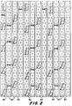
- the axial separator 24 includes a cylindrical one Rotor housing 38 and one rotatably arranged within it Rotor 39.
- the rotor 39 contains a hollow cylindrical Drum with twelve raised and longitudinally extending Hollow beams 40 on their outer peripheral surface are welded on.
- the hollow beam 40, the z. B. a U-shaped Can have cross-section, the legs on the drum, are with a variety of mounting holes 42 provided, via the goods registration elements 44 be attached.
- the Good detection elements 44a arranged in the lower region its longitudinal axis at an angle of approximately 20 ° to the axis of rotation of the rotor 39 placed on this. These goods registration elements 44a are in the threshing area of the Axial separator 24.
- the next and subsequent Group of good detection elements 44b is under one Aligned and located at an angle of 10 ° to the axis of rotation itself in the separation area of the axial separation device 24.
- the last group of goods detection elements 44c runs at an angle of 0 ° to the axis of rotation and is located in the discharge area of the axial separator 24.
- the good detection elements designated 44a, 44b and 44c are, apart from their arrangement on the rotor 39, they are identical.
- the goods detection elements 44 shown are corresponding a rotation of the rotor 39 counterclockwise aligned if you take the position of one in front of the Combine 10 standing and looking to the rear Viewer.
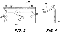
- Each goods detection element 44 is more or less of a molded sheet formed from a mounting plate 46 and a sloping crop attack plate 48 composed.
- the mounting plate 46 becomes this used, the material detection element 44 on the lengthways to extend the hollow support 40 of the rotor 39.
- the Mounting plate 46 has five mounting holes 52 and two almost semicircular mounting slots 54 Mistake.
- the mounting holes 52 are arranged such that at least three of them with the mounting holes 42 in the hollow beams 40 are in alignment when the material detection elements 44 an angle of 10 ° or 20 ° to the axis of rotation take in.
- Two mounting holes 52 are aligned the mounting holes 42 in the hollow beams 40 when the Good detection elements 44 at an angle of 0 ° to the Axis of rotation.
- the mounting slots 54 are for extreme fastening conditions are provided in which the Mounting holes and bores 42 and 52 are not sufficient. For fastening the goods detection elements 44 to the hollow beams 40 become corresponding screws, not shown used.
- the inclined crop attack plate 48 extends from the mounting plate 46 upwards, d. H. after Attachment on the rotor 39 radially outwards, under one acute angle.
- the crop attack plate 48 is inclined with one rising leading edge 56 and a radial extending edge 58 provided.
- the radial edge 58 is at right angles to the mounting plate 46 and serves the material from the rotor 39 radially outwards to move so that it engages the helical Skids and the separator grate in the rotor housing 38 is coming.
Landscapes
- Life Sciences & Earth Sciences (AREA)
- Environmental Sciences (AREA)
- Threshing Machine Elements (AREA)
Claims (7)
- Organe (44) de saisie de la matière à récolter, dans un séparateur axial (24) comportant une plaque de fixation (46), à partir de laquelle s'étend une plaque (48) d'accrochage de la matière à récolter, caractérisé en ce que la plaque (48) d'accrochage de la matière à récolter fait un angle aigu par rapport à la plaque de fixation (46) et qu'un bord (58), qui fait un angle droit par rapport à la plaque de fixation (46), se raccorde à la plaque (48) d'accrochage de la matière à récolter, sur le côté de cette plaque tourné à l'opposé de la plaque de fixation (46).
- Organe de saisie de la matière à récolter selon la revendication 1, caractérisé en ce qu'un bord avant incliné (56) est prévu sur la plaque (48) d'accrochage de la matière à récolter.
- Organe de saisie de la matière à récolter selon une ou plusieurs des revendications précédentes, caractérisé en ce que dans la plaque de fixation (46) sont prévus plusieurs perçages de fixation (52) et/ou fentes de fixation (54).
- Séparateur axial comportant un rotor (39), qui est monté de manière à pouvoir tourner dans un carter (38) du rotor et sur la surface circonférentielle extérieure duquel des organes (44) de saisie de la matière à récolter, notamment selon une ou plusieurs des revendications précédentes 1 à 3, sont montés au moyen d'une plaque de fixation (46), à partir de laquelle s'étend respectivement, vers l'extérieur, une plaque (48) d'accrochage de la matière à récolter, caractérisé en ce que la plaque (48) d'accrochage de la matière à récolter qui fait un angle aigu par rapport à la plaque de fixation (46) et qu'un bord (58), qui fait un angle droit par rapport à la plaque de fixation (46), se raccorde à la plaque (48) d'accrochage de la matière à récolter, sur le côté de cette plaque tourné à l'opposé de la plaque de fixation (46).
- Séparateur axial selon la revendication 4, caractérisé en ce que des trous de fixation (42) sont prévus dans la surface circonférentielle du rotor (39) ou dans des supports creux (40) montés sur ce rotor.
- Séparateur axial selon les revendications 4 et 5, caractérisé en ce que des organes (44) de saisie de la matière à récolter peuvent être fixés dans des différentes positions par rapport à l'axe de rotation du rotor (39), à l'aide de trous et de perçages de fixation (42, 52) formés dans les organes (44) de saisie de la matière à récolter ou dans le rotor (39) ou dans les supports creux (40).
- Séparateur axial selon les revendications 4 à 6, caractérisé en ce que les organes (44a) de saisie de la matière à récolter sont disposés sur le rotor (39) en faisant un angle de 20° par rapport à l'axe de rotation du ROTOR, dans une zone de battage, et/ou que les organes (44b) de saisie de la matière à récolter sont disposés sur le rotor en faisant un angle de 10° par rapport à cet axe, dans une zone de séparation et/ou que les organes (44c) de détection de la matière à récolter sont disposés sur le rotor de manière à faire un angle de 0° par rapport à cet axe, dans une zone de délivrance de la matière.
Applications Claiming Priority (2)
| Application Number | Priority Date | Filing Date | Title |
|---|---|---|---|
| US08/053,054 US5376047A (en) | 1993-04-26 | 1993-04-26 | Crop engaging element for an axial agricultural combine |
| US53054 | 1993-04-26 |
Publications (2)
| Publication Number | Publication Date |
|---|---|
| EP0622014A1 EP0622014A1 (fr) | 1994-11-02 |
| EP0622014B1 true EP0622014B1 (fr) | 1998-07-01 |
Family
ID=21981631
Family Applications (1)
| Application Number | Title | Priority Date | Filing Date |
|---|---|---|---|
| EP94106029A Expired - Lifetime EP0622014B1 (fr) | 1993-04-26 | 1994-04-19 | Elément attaquant la récolte pour séparateur à écoulement axial |
Country Status (7)
| Country | Link |
|---|---|
| US (1) | US5376047A (fr) |
| EP (1) | EP0622014B1 (fr) |
| AU (1) | AU669415B2 (fr) |
| BR (1) | BR9401363A (fr) |
| CA (1) | CA2119709C (fr) |
| DE (1) | DE59406348D1 (fr) |
| DK (1) | DK0622014T3 (fr) |
Families Citing this family (23)
| Publication number | Priority date | Publication date | Assignee | Title |
|---|---|---|---|---|
| US6036598A (en) * | 1998-05-21 | 2000-03-14 | Deere & Company | Crop processing element for a rotary combine |
| ITVI980113A1 (it) * | 1998-06-10 | 1999-12-10 | Giuseppe Loppoli | Carro trincia-miscelatore-distributore per il trattamento di materiali adatti alla produzione di compost |
| US6325714B1 (en) | 1999-10-07 | 2001-12-04 | Case Corporation | Rotor assembly for a combine |
| GB2356546A (en) * | 1999-11-26 | 2001-05-30 | Ford New Holland Nv | Threshing and separating unit for axial flow combines |
| US6375564B1 (en) * | 1999-11-29 | 2002-04-23 | Deere & Company | Ramp segment for a combine rotor |
| US6600019B2 (en) * | 2000-01-06 | 2003-07-29 | Curagen Corporation | Polypeptides and nucleic acids encoding same |
| DE10047464A1 (de) * | 2000-09-21 | 2002-04-11 | Deere & Co | Mähdrescher mit Axialabscheider und Auswurftrommel |
| US7028457B2 (en) * | 2003-01-10 | 2006-04-18 | Cnh America Llc | Threshing plate for a tailings conveyor of an agricultural combine |
| US7070498B2 (en) | 2003-07-29 | 2006-07-04 | Deere & Company | Frusto-conical drum infeed and threshing region for a combine rotor |
| GB2407750A (en) * | 2003-11-06 | 2005-05-11 | Cnh Belgium Nv | Axial flow combine harvester with adaptable separating unit |
| US7022013B1 (en) * | 2004-11-17 | 2006-04-04 | Cnh America Llc | Axial flow combine harvester with adaptable separating unit |
| US20070026913A1 (en) * | 2005-07-27 | 2007-02-01 | Kuchar George J | Crop processing element for a rotary combine |
| US20070049366A1 (en) * | 2005-08-26 | 2007-03-01 | Pope Glenn E | Threshing tine for a combine rotor |
| US7632182B2 (en) * | 2007-01-05 | 2009-12-15 | Cnh America Llc | Locking system for attaching a threshing and/or separating element to a rotor of a threshing system |
| US8146231B2 (en) * | 2007-05-23 | 2012-04-03 | Cnh America Llc | Insertion tool for a rotary chopper element of an integral chopper assembly of a combine harvester |
| US7717777B2 (en) * | 2007-11-29 | 2010-05-18 | Deere & Company | Adjustable rear rotor discharge flights |
| US7762877B2 (en) * | 2007-11-29 | 2010-07-27 | Deere & Company | Tailing re-thresher rasp bar and rotor housing |
| US8221202B2 (en) * | 2007-11-29 | 2012-07-17 | Deere & Company | Fully tapered rotor nose and threshing section |
| US7654892B2 (en) * | 2007-11-29 | 2010-02-02 | Deere & Company | Tailings re-thresher deflector |
| US8075377B2 (en) * | 2007-11-29 | 2011-12-13 | Deere & Company | Rear rotor cone |
| US20100257984A1 (en) * | 2009-04-09 | 2010-10-14 | Scaroni David W | Produce processing apparatus |
| US9221186B2 (en) * | 2009-04-09 | 2015-12-29 | David W. Scaroni | Produce processing apparatus |
| CN109089561A (zh) * | 2018-07-22 | 2018-12-28 | 邹铁梅 | 一种农业谷物秸秆脱粒粉碎装置 |
Family Cites Families (15)
| Publication number | Priority date | Publication date | Assignee | Title |
|---|---|---|---|---|
| DE57380C (de) * | GUSTAVPARTKE 6 COMP, in Berlin, Stallschreiberstr. 9 | Ofenthür-Verschlufs | ||
| DE191399C (fr) * | ||||
| DE419786C (de) * | 1922-10-25 | 1925-10-10 | Ncr Co | Registrierkasse mit einer Vorrichtung zum Drucken von Zwischen- und Endsummen |
| US2334461A (en) * | 1940-11-16 | 1943-11-16 | Int Harvester Co | Raking attachment for thresher cylinders |
| CA931850A (en) * | 1968-04-17 | 1973-08-14 | White Motor Corporation Of Canada Limited | Combine harvester |
| BE788802A (nl) * | 1971-07-06 | 1973-01-02 | Clayson Nv | Verbeteringen aan maaidorsers. |
| DE2909254C2 (de) * | 1978-03-10 | 1986-10-23 | Deere & Co., Moline, Ill., US, Niederlassung Deere & Co. European Office, 6800 Mannheim | Mähdrescher in Axialflußbauart |
| US4348855A (en) * | 1980-09-22 | 1982-09-14 | International Harvester Company | Crop damage responsive control of rotor speed |
| US4362168A (en) * | 1981-01-30 | 1982-12-07 | Deere & Company | Separator for an axial flow rotary combine |
| DE3717501C2 (de) * | 1987-05-23 | 1995-01-19 | Claas Ohg | Selbstfahrender Mähdrescher |
| GB8810759D0 (en) * | 1988-05-06 | 1988-06-08 | Ford New Holland Nv | Axial flow harvesting machine |
| US4889517A (en) * | 1989-05-05 | 1989-12-26 | Ford New Holland, Inc. | Overlapping rasp bar rotor for axial flow combines |
| DE3932370A1 (de) * | 1989-09-28 | 1991-04-11 | Claas Ohg | Selbstfahrender maehdrescher |
| US5152717A (en) * | 1991-05-10 | 1992-10-06 | Deere & Company | Tooth mounting assembly for axial separator |
| US5125871A (en) * | 1991-05-21 | 1992-06-30 | Gorden Marvin J | Axial flow combine rotor having helical extension members in forward threshing area |
-
1993
- 1993-04-26 US US08/053,054 patent/US5376047A/en not_active Expired - Fee Related
-
1994
- 1994-02-24 AU AU56381/94A patent/AU669415B2/en not_active Ceased
- 1994-03-23 CA CA002119709A patent/CA2119709C/fr not_active Expired - Fee Related
- 1994-03-30 BR BR9401363A patent/BR9401363A/pt not_active IP Right Cessation
- 1994-04-19 DE DE59406348T patent/DE59406348D1/de not_active Expired - Fee Related
- 1994-04-19 DK DK94106029T patent/DK0622014T3/da active
- 1994-04-19 EP EP94106029A patent/EP0622014B1/fr not_active Expired - Lifetime
Also Published As
| Publication number | Publication date |
|---|---|
| DK0622014T3 (da) | 1999-04-12 |
| CA2119709C (fr) | 1997-10-07 |
| AU5638194A (en) | 1994-11-03 |
| AU669415B2 (en) | 1996-06-06 |
| US5376047A (en) | 1994-12-27 |
| BR9401363A (pt) | 1994-11-22 |
| EP0622014A1 (fr) | 1994-11-02 |
| CA2119709A1 (fr) | 1994-10-27 |
| DE59406348D1 (de) | 1998-08-06 |
Similar Documents
| Publication | Publication Date | Title |
|---|---|---|
| EP0622014B1 (fr) | Elément attaquant la récolte pour séparateur à écoulement axial | |
| EP0631716B1 (fr) | Dispositif batteur-séparateur à écoulement axial | |
| EP0617884B1 (fr) | TÔle d'entrée d'un séparateur axial | |
| EP0958733B1 (fr) | Rotor pour dispositif batteur-séparateur à écoulement axial | |
| DE2000554B2 (de) | Mähdrescher | |
| DE2433948A1 (de) | Ernte- und dreschmaschine | |
| EP1226747B1 (fr) | Tambour avec éléments entraíneurs interchangeables | |
| EP1228683A2 (fr) | Moissoneuse batteuse avec un transporteur rotatif | |
| EP2457434A1 (fr) | Panier de battage doté d'au moins un insert démontable | |
| EP2011384A1 (fr) | Unité de traitement de récoltes dotée d'un nombre de rotations dépendant du débit | |
| DE102007031807A1 (de) | Abscheidetrommel für ein Mehrtrommeldreschwerk | |
| DE102016217609B4 (de) | Mähdrescher mit Strohrutsche und Strohförderer | |
| DE3709242C2 (fr) | ||
| EP1500323B1 (fr) | Elément de traitement de produit de récolte pour un rotor d'un dispositif pour le traitement de récolte d'une moissonneuse-batteuse | |
| DE3139933A1 (de) | Selbstfahrender maehdrescher in axialflussbauart | |
| DE102012204416A1 (de) | Mehrtrommeldreschwerk | |
| EP0503444A1 (fr) | Batte pour batteur cylindrique | |
| EP1354508B1 (fr) | Separateur axial avec rail de guidage | |
| EP0622013B1 (fr) | Dispositif pour séparer axial | |
| DE102013202050B4 (de) | Dreschwerk mit einer Wendetrommel und einer Abstreifrolle | |
| DE3223927A1 (de) | Selbstfahrender maehdrescher | |
| EP1163833A1 (fr) | Dispositif séparateur à écoulement axial muni d'un dispositif de guidage à la sortie | |
| DE602004003542T2 (de) | Axialdreschmähdrescher mit adaptierbarer Trennvorrichtung | |
| DE102011088543B4 (de) | Mähdrescher mit einer zwischen der Drescheinrichtung und der Reinigung angeordneten Nachdrescheinrichtung | |
| DE19615778A1 (de) | Dreschtrommel |
Legal Events
| Date | Code | Title | Description |
|---|---|---|---|
| PUAI | Public reference made under article 153(3) epc to a published international application that has entered the european phase |
Free format text: ORIGINAL CODE: 0009012 |
|
| AK | Designated contracting states |
Kind code of ref document: A1 Designated state(s): BE DE DK FR GB IT |
|
| 17P | Request for examination filed |
Effective date: 19950209 |
|
| 17Q | First examination report despatched |
Effective date: 19961203 |
|
| GRAG | Despatch of communication of intention to grant |
Free format text: ORIGINAL CODE: EPIDOS AGRA |
|
| GRAG | Despatch of communication of intention to grant |
Free format text: ORIGINAL CODE: EPIDOS AGRA |
|
| GRAH | Despatch of communication of intention to grant a patent |
Free format text: ORIGINAL CODE: EPIDOS IGRA |
|
| GRAH | Despatch of communication of intention to grant a patent |
Free format text: ORIGINAL CODE: EPIDOS IGRA |
|
| GRAA | (expected) grant |
Free format text: ORIGINAL CODE: 0009210 |
|
| AK | Designated contracting states |
Kind code of ref document: B1 Designated state(s): BE DE DK FR GB IT |
|
| GBT | Gb: translation of ep patent filed (gb section 77(6)(a)/1977) |
Effective date: 19980713 |
|
| REF | Corresponds to: |
Ref document number: 59406348 Country of ref document: DE Date of ref document: 19980806 |
|
| ET | Fr: translation filed | ||
| REG | Reference to a national code |
Ref country code: DK Ref legal event code: T3 |
|
| PLBE | No opposition filed within time limit |
Free format text: ORIGINAL CODE: 0009261 |
|
| STAA | Information on the status of an ep patent application or granted ep patent |
Free format text: STATUS: NO OPPOSITION FILED WITHIN TIME LIMIT |
|
| 26N | No opposition filed | ||
| REG | Reference to a national code |
Ref country code: GB Ref legal event code: IF02 |
|
| PGFP | Annual fee paid to national office [announced via postgrant information from national office to epo] |
Ref country code: GB Payment date: 20050413 Year of fee payment: 12 |
|
| PGFP | Annual fee paid to national office [announced via postgrant information from national office to epo] |
Ref country code: FR Payment date: 20050418 Year of fee payment: 12 |
|
| PGFP | Annual fee paid to national office [announced via postgrant information from national office to epo] |
Ref country code: DK Payment date: 20050425 Year of fee payment: 12 |
|
| PGFP | Annual fee paid to national office [announced via postgrant information from national office to epo] |
Ref country code: DE Payment date: 20050430 Year of fee payment: 12 |
|
| PGFP | Annual fee paid to national office [announced via postgrant information from national office to epo] |
Ref country code: BE Payment date: 20050520 Year of fee payment: 12 |
|
| PG25 | Lapsed in a contracting state [announced via postgrant information from national office to epo] |
Ref country code: GB Free format text: LAPSE BECAUSE OF NON-PAYMENT OF DUE FEES Effective date: 20060419 |
|
| PG25 | Lapsed in a contracting state [announced via postgrant information from national office to epo] |
Ref country code: BE Free format text: LAPSE BECAUSE OF NON-PAYMENT OF DUE FEES Effective date: 20060430 |
|
| PGFP | Annual fee paid to national office [announced via postgrant information from national office to epo] |
Ref country code: IT Payment date: 20060430 Year of fee payment: 13 |
|
| PG25 | Lapsed in a contracting state [announced via postgrant information from national office to epo] |
Ref country code: DK Free format text: LAPSE BECAUSE OF NON-PAYMENT OF DUE FEES Effective date: 20060501 |
|
| PG25 | Lapsed in a contracting state [announced via postgrant information from national office to epo] |
Ref country code: DE Free format text: LAPSE BECAUSE OF NON-PAYMENT OF DUE FEES Effective date: 20061101 |
|
| REG | Reference to a national code |
Ref country code: DK Ref legal event code: EBP |
|
| GBPC | Gb: european patent ceased through non-payment of renewal fee |
Effective date: 20060419 |
|
| REG | Reference to a national code |
Ref country code: FR Ref legal event code: ST Effective date: 20061230 |
|
| BERE | Be: lapsed |
Owner name: *DEERE & CY Effective date: 20060430 |
|
| PG25 | Lapsed in a contracting state [announced via postgrant information from national office to epo] |
Ref country code: FR Free format text: LAPSE BECAUSE OF NON-PAYMENT OF DUE FEES Effective date: 20060502 |
|
| PG25 | Lapsed in a contracting state [announced via postgrant information from national office to epo] |
Ref country code: IT Free format text: LAPSE BECAUSE OF NON-PAYMENT OF DUE FEES Effective date: 20070419 |