EP0622441B1 - Mélange de cristaux liquides ferro-électriques et dispositif à cristaux liquides l'utilisant - Google Patents
Mélange de cristaux liquides ferro-électriques et dispositif à cristaux liquides l'utilisant Download PDFInfo
- Publication number
- EP0622441B1 EP0622441B1 EP94302992A EP94302992A EP0622441B1 EP 0622441 B1 EP0622441 B1 EP 0622441B1 EP 94302992 A EP94302992 A EP 94302992A EP 94302992 A EP94302992 A EP 94302992A EP 0622441 B1 EP0622441 B1 EP 0622441B1
- Authority
- EP
- European Patent Office
- Prior art keywords
- liquid crystal
- ferroelectric liquid
- formula
- compound represented
- group
- Prior art date
- Legal status (The legal status is an assumption and is not a legal conclusion. Google has not performed a legal analysis and makes no representation as to the accuracy of the status listed.)
- Expired - Lifetime
Links
- 0 C**B*C(CCC1*C)C(CC2)C2C1C(F)(F)F Chemical compound C**B*C(CCC1*C)C(CC2)C2C1C(F)(F)F 0.000 description 5
- FRAIDKALXFEOLL-UHFFFAOYSA-N CC1C=CC(C2C=CC(O)=CC2)=CC1 Chemical compound CC1C=CC(C2C=CC(O)=CC2)=CC1 FRAIDKALXFEOLL-UHFFFAOYSA-N 0.000 description 1
- VCCBEIPGXKNHFW-UHFFFAOYSA-N Oc(cc1)ccc1-c(cc1)ccc1O Chemical compound Oc(cc1)ccc1-c(cc1)ccc1O VCCBEIPGXKNHFW-UHFFFAOYSA-N 0.000 description 1
Images








Classifications
-
- C—CHEMISTRY; METALLURGY
- C07—ORGANIC CHEMISTRY
- C07D—HETEROCYCLIC COMPOUNDS
- C07D309/00—Heterocyclic compounds containing six-membered rings having one oxygen atom as the only ring hetero atom, not condensed with other rings
- C07D309/02—Heterocyclic compounds containing six-membered rings having one oxygen atom as the only ring hetero atom, not condensed with other rings having no double bonds between ring members or between ring members and non-ring members
- C07D309/08—Heterocyclic compounds containing six-membered rings having one oxygen atom as the only ring hetero atom, not condensed with other rings having no double bonds between ring members or between ring members and non-ring members with hetero atoms or with carbon atoms having three bonds to hetero atoms with at the most one bond to halogen, e.g. ester or nitrile radicals, directly attached to ring carbon atoms
- C07D309/10—Oxygen atoms
-
- C—CHEMISTRY; METALLURGY
- C09—DYES; PAINTS; POLISHES; NATURAL RESINS; ADHESIVES; COMPOSITIONS NOT OTHERWISE PROVIDED FOR; APPLICATIONS OF MATERIALS NOT OTHERWISE PROVIDED FOR
- C09K—MATERIALS FOR MISCELLANEOUS APPLICATIONS, NOT PROVIDED FOR ELSEWHERE
- C09K19/00—Liquid crystal materials
- C09K19/04—Liquid crystal materials characterised by the chemical structure of the liquid crystal components, e.g. by a specific unit
- C09K19/06—Non-steroidal liquid crystal compounds
- C09K19/34—Non-steroidal liquid crystal compounds containing at least one heterocyclic ring
- C09K19/3402—Non-steroidal liquid crystal compounds containing at least one heterocyclic ring having oxygen as hetero atom
-
- C—CHEMISTRY; METALLURGY
- C09—DYES; PAINTS; POLISHES; NATURAL RESINS; ADHESIVES; COMPOSITIONS NOT OTHERWISE PROVIDED FOR; APPLICATIONS OF MATERIALS NOT OTHERWISE PROVIDED FOR
- C09K—MATERIALS FOR MISCELLANEOUS APPLICATIONS, NOT PROVIDED FOR ELSEWHERE
- C09K19/00—Liquid crystal materials
- C09K19/04—Liquid crystal materials characterised by the chemical structure of the liquid crystal components, e.g. by a specific unit
- C09K19/42—Mixtures of liquid crystal compounds covered by two or more of the preceding groups C09K19/06 - C09K19/40
-
- C—CHEMISTRY; METALLURGY
- C09—DYES; PAINTS; POLISHES; NATURAL RESINS; ADHESIVES; COMPOSITIONS NOT OTHERWISE PROVIDED FOR; APPLICATIONS OF MATERIALS NOT OTHERWISE PROVIDED FOR
- C09K—MATERIALS FOR MISCELLANEOUS APPLICATIONS, NOT PROVIDED FOR ELSEWHERE
- C09K19/00—Liquid crystal materials
- C09K19/04—Liquid crystal materials characterised by the chemical structure of the liquid crystal components, e.g. by a specific unit
- C09K19/42—Mixtures of liquid crystal compounds covered by two or more of the preceding groups C09K19/06 - C09K19/40
- C09K19/44—Mixtures of liquid crystal compounds covered by two or more of the preceding groups C09K19/06 - C09K19/40 containing compounds with benzene rings directly linked
-
- C—CHEMISTRY; METALLURGY
- C09—DYES; PAINTS; POLISHES; NATURAL RESINS; ADHESIVES; COMPOSITIONS NOT OTHERWISE PROVIDED FOR; APPLICATIONS OF MATERIALS NOT OTHERWISE PROVIDED FOR
- C09K—MATERIALS FOR MISCELLANEOUS APPLICATIONS, NOT PROVIDED FOR ELSEWHERE
- C09K19/00—Liquid crystal materials
- C09K19/04—Liquid crystal materials characterised by the chemical structure of the liquid crystal components, e.g. by a specific unit
- C09K19/42—Mixtures of liquid crystal compounds covered by two or more of the preceding groups C09K19/06 - C09K19/40
- C09K19/46—Mixtures of liquid crystal compounds covered by two or more of the preceding groups C09K19/06 - C09K19/40 containing esters
-
- C—CHEMISTRY; METALLURGY
- C09—DYES; PAINTS; POLISHES; NATURAL RESINS; ADHESIVES; COMPOSITIONS NOT OTHERWISE PROVIDED FOR; APPLICATIONS OF MATERIALS NOT OTHERWISE PROVIDED FOR
- C09K—MATERIALS FOR MISCELLANEOUS APPLICATIONS, NOT PROVIDED FOR ELSEWHERE
- C09K19/00—Liquid crystal materials
- C09K19/04—Liquid crystal materials characterised by the chemical structure of the liquid crystal components, e.g. by a specific unit
- C09K19/06—Non-steroidal liquid crystal compounds
- C09K19/34—Non-steroidal liquid crystal compounds containing at least one heterocyclic ring
- C09K19/3402—Non-steroidal liquid crystal compounds containing at least one heterocyclic ring having oxygen as hetero atom
- C09K2019/3422—Non-steroidal liquid crystal compounds containing at least one heterocyclic ring having oxygen as hetero atom the heterocyclic ring being a six-membered ring
Definitions
- the present invention relates to a ferroelectric liquid crystal mixture and a liquid crystal device using the same.
- Liquid crystal display devices which have been most widely used in recent years employ a nematic phase of liquid crystal.
- twisted nematic (TN) liquid crystal display devices it is difficult to realize a display with a large capacity, e.g., 2000 x 2000 lines, since contrast decreases with the increase in the number of lines.
- STN supertwisted nematic
- DSTN double layer supertwisted nematic
- Active matrix type liquid crystal display devices have been developed to realize a display with a large capacity, e.g., 1000 x 1000 lines. These devices also have disadvantages such as many steps for prolonged production, a decrease in yield, and high production cost.
- ferroelectric liquid crystal display device In recent years, in addition to liquid crystal display devices employing a nematic phase, those employing a smectic phase have been extensively studied. In particular, a ferroelectric liquid crystal display device has been considered to be promising (N. A. Clark et al., Appl. Phys. Lett., 36, 899 (1980)). The ferroelectric liquid crystal display device employs a memory property of a chiral smectic C phase, a chiral smectic I phase, and the like. Because of this, the ferroelectric liquid crystal display device enables a display with a large capacity accompanied by the decrease in response time.
- the ferroelectric liquid crystal display device does not require an active element such as a thin film transistor, production cost is not likely to increase. Furthermore, the ferroelectric liquid crystal display device has an advantage of a large viewing angle, so that it has been promising as a display device with a large capacity, e.g., 2000 x 2000 lines.
- a method (1) is proposed in T. Uemura et al., Proc. SID, 175 (1987) . This method requires oblique vacuum evaporation, making it difficult to mass-produce a device and to obtain a device with a large area.
- Another method (2) is proposed in N. Yamamoto et al., Jpn. J. Appl. Phys., 28, 524 (1989). According to the experiences of the inventors, it is not so easy to obtain uniform orientation in a large area using a high pretilt alignment film.
- Another method (3) is proposed in Y. Sato et al., Jpn. J. Appl. Phys., 28, L483 (1989) and in H. Rieger et al., Proc.
- a parallel rubbing cell refers to a liquid crystal cell fabricated so that rubbing directions of the upper and lower alignment films are identical. In this method, it is difficult to selectively obtain Cl-uniform orientation in a large area.
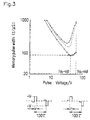
- a conventional ferroelectric liquid crystal material whose dielectric anisotropy is not negative exhibits a ⁇ -V characteristic shown in Figure 1A . More specifically, ⁇ (a memory pulse width, or a pulse width required for memory) monotonously decreases with the increase in voltage. In contrast, a ferroelectric liquid crystal material having negative dielectric anisotropy exhibits a ⁇ -V ( ⁇ -V min ) characteristic having a local minimum value V min shown in Figure 1B .
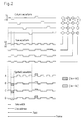
- Surguy et al. have reported a driving method shown in Figure 2 as a driving method using this characteristic (P.W.H. Surguy et al., Ferroelectrics, 122, 63 (1991)). The principle of this driving method is briefly shown in Figure 3 .
- a problem of the method (6) lies in the high driving voltage.
- the driving voltage of a sample of a ferroelectric liquid crystal display device is 55 V.
- the price of an IC driver for driving the ferroelectric liquid crystal display device goes up with the increase in voltage, so that a high driving voltage necessitates the increase in production cost.
- a high driving voltage is due to a high local minimum value V min in the ⁇ -V min characteristic.
- a ferroelectric liquid crystal display material exhibiting a local minimum value of about 30 V needs to be developed.
- E min is a local minimum value of electric field intensity
- d is the cell thickness
- P s spontaneous polarization
- ⁇ dielectric anisotropy
- ⁇ is the tilt angle.
- the ferroelectric liquid crystal mixture is prepared by adding a chiral compound to an achiral liquid crystal mixture exhibiting a smectic C phase. Therefore, it is required that a chiral compound which can cause high response in a small amount is added to an achiral liquid crystal mixture having low viscosity.
- a chiral compound generally has high viscosity, so that its added amount is preferably small.
- the tilt angle, refractive index, specific resistance, and the like can be optimized.
- the ferroelectric liquid crystal mixture of this invention contains at least one compound selected from the group consisting of a compound represented by the following general Formula I: where R 1 and R 2 are the same or different straight-chain or branched chain alkyl groups having 1 to 15 carbon atoms; X 1 is a single bond, -O-, -COO-, or -OCO-; X 2 is -O- or -OCO-; Y is -COO- or -CH 2 O-; A and B are independently a group including a six membered ring which can be substituted by halogen, a cyano group, a lower alkoxy group, or a fluorine-containing alkyl group; and Z is a single bond, -COO-, or -OCO-, and a compound represented by the following general Formula II: where R 1 and R 2 are the same or different straight-chain or branched chain alkyl groups having 1 to 15 carbon atoms; X 1 is a single bond, -
- the compound represented by Formula I and the compound represented by Formula II are chiral compounds.
- the above-mentioned ferroelectric liquid crystal mixture contains the chiral compound represented by Formula I and the chiral compound represented by Formula II.
- the above-mentioned ferroelectric liquid crystal mixture exhibits a chiral smectic C phase, a smectic A phase, and a chiral nematic phase.
- the above-mentioned ferroelectric liquid crystal mixture contains a compound represented by the following general Formula III: where R 1 and R 2 are the same or different straight-chain or branched chain alkyl groups having 1 to 15 carbon atoms; X 1 is a single bond, -O-, -COO-, or -OCO-; X 3 is a single bond, -0-, -COO-, or -OCO-; A is a group including a six membered ring which can be substituted by halogen, a cyano group, a lower alkoxy group, or a fluorine-containing alkyl group; Z is a single bond, -COO-, or -OCO-; Q 1 and Q 2 are H, F, CN, or CF 3 , and at least one of Q 1 and Q 2 is not H.
- R 1 and R 2 are the same or different straight-chain or branched chain alkyl groups having 1 to 15 carbon atoms
- X 1 is
- R 1 and R 2 are independently a straight chain or branched chain alkyl group having 5 to 8 carbon atoms
- a and B are independently a phenylene group which can be substituted by halogen, a cyano group, a lower alkoxy group, or a fluorine-containing alkyl group
- Z is a single bond in Formula I or II.
- the chiral compound is selected from the group consisting of a compound represented by the following Formulae and enantiomers thereof.
- the chiral compound is selected from the group consisting of a compound represented by the following Formulae and enantiomers.
- the above-mentioned ferroelectric liquid crystal mixture contains the compound represented by Formula I in an amount of 0.01 to 5 wt% based on the total amount of the ferroelectric liquid crystal mixture.
- the above-mentioned ferroelectric liquid crystal mixture contains the compound represented by Formula II in an amount of 0.01 to 5 wt% based on the total amount of the ferroelectric liquid crystal mixture.
- the compound represented by Formula I and the compound represented by Formula II are achiral compounds, and the achiral compounds are contained in the above-mentioned ferroelectric liquid crystal mixture in an amount of 5 to 20 wt% based on the total amount of the ferroelectric liquid crystal mixture.
- a liquid crystal device comprises a pair of facing substrates, liquid crystal sandwiched between the pair of substrates, means for aligning the liquid crystal, and means for applying a voltage to the liquid crystal, wherein the liquid crystal is made of a ferroelectric liquid crystal mixture having negative dielectric anisotropy and exhibiting a chiral smectic C phase containing a compound selected from the group consisting of the compound represented by Formula I and the compound represented by Formula II.
- the compound represented by Formula I and the compound represented by Formula II are chiral compounds.
- the invention described herein makes possible the advantage of providing a ferroelectric liquid crystal mixture having a low local minimum value V min and a liquid crystal device using the same.
- Figures 1A and 1B are graphs showing ⁇ -V characteristics of ferroelectric liquid crystal devices.
- Figure 2 is a timing chart showing an example of driving waveforms used for driving the ferroelectric liquid crystal device having the ⁇ -V characteristic of Figure 1B .
- Figure 3 is a diagram illustrating a principle of a method for driving using the driving waveforms of Figure 2 .
- Figure 4 is a cross-sectional view of a ferroelectric liquid crystal device of the present invention.
- Figures 5A and 5B are model diagrams showing C1 and C2 orientations in the ferroelectric liquid crystal device of the present invention.
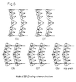
- Figure 6 shows models of four molecular orientations of ferroelectric liquid crystal.
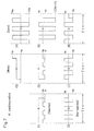
- Figure 7 is a timing chart showing an example of driving waveforms used for driving the ferroelectric liquid crystal device having the ⁇ -V characteristic of Figure 1B .
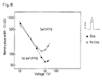
- Figure 8 is a graph showing a ⁇ -V characteristic of the ferroelectric liquid crystal device of the present invention.
- Figure 9 is a graph showing a ⁇ -V characteristic in the case where a bias is applied to another ferroelectric liquid crystal device of the present invention.
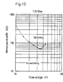
- Figure 10 is a graph showing a ⁇ -V characteristic in the case where a bias is applied to still another ferroelectric liquid crystal device of the present invention.
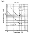
- Figure 11 is a graph showing ⁇ -V characteristics in the case where a bias is applied to the other two ferroelectric liquid crystal devices of the present invention.
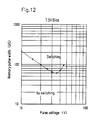
- Figure 12 is a graph showing a ⁇ -V characteristic in the case where a bias is applied to still another ferroelectric liquid crystal device of the present invention.
- Figure 13 is a graph showing a ⁇ -V characteristic in the case where a bias is applied to still another ferroelectric liquid crystal device of the present invention.
- Figure 14 is a graph showing a ⁇ -V characteristic in the case where a bias is applied to still another ferroelectric liquid crystal device of the present invention.
- Figure 15 shows an example of driving waveforms for driving a ferroelectric liquid crystal device using a ⁇ -V min characteristic.
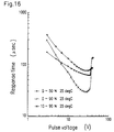
- Figure 16 is a graph showing the relationship between response time and a pulse voltage of a ferroelectric liquid crystal device of a comparative example.
- Figure 17 is a graph showing the relationship between response time and a pulse voltage of a ferroelectric liquid crystal device of another comparative example.
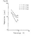
- Figure 18 is a graph showing the relationship between response time and a pulse voltage of a ferroelectric liquid crystal device of still another comparative example.
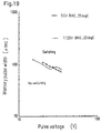
- Figure 19 is a graph showing a ⁇ -V characteristic of a ferroelectric liquid crystal device of a comparative example.
- Figure 20 is a graph showing a ⁇ -V characteristic of a ferroelectric liquid crystal device of another comparative example.
- Optically active substances represented by Formulae IV to VII can be synthesized as follows:
- the above reaction can be carried out by a conventional method.
- R 1 and R 2 are the same or different straight-chain or branched chain alkyl groups having 1 to 15 carbon atoms;
- X 1 is a single bond, -O-, -COO-, or -OCO-;
- X 2 is -O- or -OCO-;
- Y is -COO- or -CH 2 O-;
- a and B are independently a group including a six membered ring which can be substituted by halogen, a cyano group, a lower alkoxy group, or a fluorine-containing alkyl group; and
- Z is a single bond, -COO-, or -OCO-.
- a compound represented by Formula I, where Z is a single bond, -COO-, or -OCO-; Y is -COO-; and X 2 is -O- can be synthesized by the following method, using the optically active substance represented by Formula VII as part of its material.
- R 1 and R 2 are the same or different straight-chain or branched chain alkyl groups having 1 to 15 carbon atoms;
- X 1 is a single bond, -O-, -COO-, or -OCO-;
- a and B are independently a group including a six membered ring which can be substituted by halogen, a cyano group, a lower alkoxy group, or a fluorine-containing alkyl group; and Hal is halogen.
- the reaction in the above method can be carried out in a solvent such as toluene, benzene, and methylene chloride in the presence of an organic base such as pyridine and triethylamine at -20°C to 80°C.
- a solvent such as toluene, benzene, and methylene chloride
- an organic base such as pyridine and triethylamine at -20°C to 80°C.
- a compound represented by Formula I, where Z is a single bond, Y is -COO-, and X 2 is -OCO-, can be synthesized by the following method, using the optically active substance represented by Formula IV as part of its material.
- R 1 and R 2 are the same or different straight-chain or branched chain alkyl groups having 1 to 15 carbon atoms;
- X 1 is a single bond, -O-, -COO-, or -OCO-;
- X 2 is -O- or -OCO-;
- a and B are independently a group including a six membered ring which can be substituted by halogen, a cyano group, a lower alkoxy group, or a fluorine-containing alkyl group; * is asymmetric carbon; and Hal is halogen.
- the esterification (i) in the above method can be effected in a solvent such as toluene, benzene, and methylene chloride in the presence of an organic base such as pyridine and triethylamine in a temperature range of -20°C to 80°C.
- a solvent such as toluene, benzene, and methylene chloride
- an organic base such as pyridine and triethylamine in a temperature range of -20°C to 80°C.
- the desilylation (ii) in the above method can be effected in a solvent of tetrahydrofran in a temperature range of 0°C to 50°C, using tetra-n-butylammonium fluoride as a catalyst.
- the acylation (iii) in the above method can be effected in a solvent such as toluene, benzene, and methylene chloride in the presence of an organic base such as pyridine and triethylamine in a temperature range of -20°C to 80°C.
- a solvent such as toluene, benzene, and methylene chloride
- an organic base such as pyridine and triethylamine in a temperature range of -20°C to 80°C.
- a compound represented by Formula I, where Z is a single bond, Y is -CH 2 O-, and X 2 is -O-, can be synthesized by the following method, using the optically active substance represented by Formula VII as part of its material.
- R 1 and R 2 are the same or different straight-chain or branched chain alkyl groups having 1 to 15 carbon atoms;
- X 1 is a single bond, -O-, -COO-, or -OCO-;
- X 2 is -O- or -OCO-;
- a and B are independently a group including a six membered ring which can be substituted by halogen, a cyano group, a lower alkoxy group, or a fluorine-containing alkyl group; and
- Z' is chlorine, bromine, iodine, or a tosyl group.
- the above-mentioned reaction is carried out by allowing a base such as an alkali metal hydride, sodium hydroxide, and potassium hydroxide to react with the compounds represented by Formula VII and adding the compound represented by Formula VIII to the reaction product.
- a base such as an alkali metal hydride, sodium hydroxide, and potassium hydroxide
- R 1 and R 2 are the same or different straight-chain or branched chain alkyl groups having 1 to 15 carbon atoms;
- X 1 is a single bond, -O-, -COO-, or -OCO-;
- X 2 is -O- or -OCO-;
- Y is -COO- or -CH 2 O-;
- a and B are independently a group including a six membered ring which can be substituted by halogen, a cyano group, a lower alkoxy group, or a fluorine-containing alkyl group; and
- Z is a single bond, -COO-, or -OCO-.
- a compound represented by Formula II, where Z is a single bond and Y is -COO- can be synthesized by the following method, using the optically active substances represented by Formula V or VI as part of its material.
- R 1 and R 2 are the same or different straight-chain or branched chain alkyl groups having 1 to 15 carbon atoms;
- X 1 is a single bond, -O-, -COO-, or -OCO-;
- X 2 is -O- or -OCO-;
- a and B are independently a group including a six membered ring which can be substituted by halogen, a cyano group, a lower alkoxy group, or a fluorine-containing alkyl group; and Hal is halogen.
- the reaction (i) in the above method can be carried out in a solvent such as toluene, benzene, and methylene chloride in the presence of an organic base such as pyridine and triethylamine in a temperature range of -20°C to 80°C.
- a solvent such as toluene, benzene, and methylene chloride
- an organic base such as pyridine and triethylamine in a temperature range of -20°C to 80°C.
- a compound represented by Formula II, where Z is a single bond and Y is -CH 2 O-, can be synthesized by the following method, using the optically active substance represented by Formula V or VI as part of its material.
- R 1 and R 2 are the same or different straight-chain or branched chain alkyl groups having 1 to 15 carbon atoms;
- X 1 is a single bond, -O-, -COO-, or -OCO-;
- X 2 is -O- or -OCO-;
- a and B are independently a group including a six membered ring which can be substituted by halogen, a cyano group, a lower alkoxy group, or a fluorine-containing alkyl group; and
- Z' is chlorine, bromine, iodine, or a tosyl group.
- the reaction (i) in the above method can be carried out by allowing the compound represented by Formula V or VI to react with a base such as alkali metal hydride, sodium hydroxide and potassium hydroxide and then adding the compound represented by Formula VIII to the resulting reaction product.
- a base such as alkali metal hydride, sodium hydroxide and potassium hydroxide
- a compound represented by Formula II, where Z is -COO- and Y is -COO- can be synthesized by the following method, using the optically active substance represented by Formula V or VI as part of its material.
- R 1 and R 2 are the same or different straight-chain or branched chain alkyl groups having 1 to 15 carbon atoms;
- X 1 is a single bond, -O-, -COO-, or -OCO-;
- X 2 is -O- or -OCO-;
- a and B are independently a group including a six membered ring which can be substituted by halogen, a cyano group, a lower alkoxy group, or a fluorine-containing alkyl group; Hal is halogen; and Bz is a benzyl group.
- the reaction (i) in the above method can be carried out in a solvent such as toluene, benzene, and methylene chloride in the presence of an organic base such as pyridine and triethylamine in a temperature range of -20°C to 80°C.
- a solvent such as toluene, benzene, and methylene chloride
- an organic base such as pyridine and triethylamine in a temperature range of -20°C to 80°C.
- the debenzylation (ii) in the above method can be effected by hydrogenolysis at atmospheric pressure, using acetic acid or an alcoholic solvent such as methanol, ethanol, and propanol in the presence of, for example, a palladium carbon (Pd/C) catalyst.
- acetic acid or an alcoholic solvent such as methanol, ethanol, and propanol in the presence of, for example, a palladium carbon (Pd/C) catalyst.
- Pd/C palladium carbon
- reaction (iii) in the above method can be carried out in a solvent of toluene, benzene, and methylene chloride in the presence of an organic base such as pyridine and triethylamine in a temperature range of -20°C to 80°C.
- organic base such as pyridine and triethylamine
- a compound represented by Formula II, where Z is -COO- and Y is -CH 2 O-, can be synthesized by the following method, using the optically reactive substance represented by Formulae V or VI as part of its material.
- R 1 and R 2 are the same or different straight-chain or branched chain alkyl groups having 1 to 15 carbon atoms;
- X 1 is a single bond, -O-, -COO-, or -OCO-;
- X 2 is -O- or -OCO-;
- a and B are independently a group including a six membered ring which can be substituted by halogen, a cyano group, a lower alkoxy group, or a fluorine-containing alkyl group;
- Hal is halogen;
- Z' is chlorine, bromine, iodine, or a tosyl group; and
- Thp is a tetrahydropyranyl group.
- the reaction (i) in the above method can be carried out by allowing the compound represented by Formula V or VI to react with a base such as an alkali metal hydride, sodium hydroxide, and potassium hydroxide and then adding the compound represented by Formula IX to the resulting reaction product.
- a base such as an alkali metal hydride, sodium hydroxide, and potassium hydroxide
- the elimination (ii) of a tetrahydropyranyl group in the above method can be effected, using a solvent such as ether, tetrahydrofuran, and chloroform in the presence of an acid catalyst such as hydrochloric acid, sulfuric acid, and p-toluenesulfonic acid.
- a solvent such as ether, tetrahydrofuran, and chloroform
- an acid catalyst such as hydrochloric acid, sulfuric acid, and p-toluenesulfonic acid.
- the reaction (iii) in the above method can be effected in a solvent such as toluene, benzene, and methylene chloride in the presence of an organic base such as pyridine and triethylamine in a temperature range of -20°C to 80°C.
- a solvent such as toluene, benzene, and methylene chloride
- an organic base such as pyridine and triethylamine in a temperature range of -20°C to 80°C.
- a known compound represented by Formula III can be synthesized by the conventional synthesis method.
- Examples of the conventional synthesis method are described in G. W. Gray, M. Hied and K. J. Toyne, Mol. Cryst. Liq. Cryst., 204, 43 (1991); Japanese Laid-Open Patent Publication Nos. 2-289529, 2-279649, 2-4725, 2-4724; and Japanese National Publication Nos. 2-504520, 2-502914, 2-503568, 2-503443, 2-503441, 2-503436, 2-503431, and 2-503430.
- Ether was removed from the extract under reduced pressure.
- the resulting extract was purified by silica gel column chromatography to obtain 0.25 g (0.5 mM) of intended compound, i.e., (2R, 5R, 6R)-tetrahydro-6-trifluoromethyl-2-hexyloxy-5-(4"-hexyloxybiphenyl-4'-carbonyloxy)pyran.
- Examples of the alkyl group having 1 to 15 carbon atoms represented by R 1 and R 2 in Formulae I and II include methyl, ethyl, n-propyl, n-butyl, isobutyl, n-pentyl, isopentyl, n-hexyl, isohexyl, n-heptyl, isoheptyl, n-octyl, isooctyl, n-nonyl, isononyl, n-decyl, isodecyl, n-undecyl, isoundecyl, n-dodecyl, isododecyl, n-tridecyl, isotridecyl, n-tetradecyl, isotetradecyl, n-pentadecyl, and isopentadecyl.
- Asymmetric carbon can be contained in a carbon chain of these alkyl groups.
- one or more hydrogen in these alkyl groups can be substituted by fluorine, chlorine, bromine, a cyano group, a nitro group, a trifluoromethyl group, a methoxy group, or the like.
- Examples of the group obtained by substituting one or more hydrogen in these alkyl groups include 1-trifluoromethylheptyl, 1-fluorooctyl, and 1-chloro-2-methyl-butyl.
- Examples of the group including a six membered ring represented by A and B include heterocyclic groups including a six membered ring having one or two nitrogen atoms (e.g., pyridine-2,5-diyl, pyrimidine-2,5-diyl, pyridazine-3,6-diyl); aromatic hydrocarbon groups (e.g., phenylene, nephthalene-2,6-diyl); and saturated hydrocarbon group including a six membered ring which can have one or two oxygen atoms (e.g., cyclohexadinyl, tetrahydropyran-2,5-diyl, dioxane-2,5-diyl).
- heterocyclic groups including a six membered ring having one or two nitrogen atoms e.g., pyridine-2,5-diyl, pyrimidine-2,5-diyl, pyridazine-3,6-d
- These groups including a six membered ring can be substituted by one or two groups selected from a halogen group (e.g., chloro, fluoro) , a cyano group, a lower alkoxy group (e.g., methoxy, ethoxy), and a fluorine-containing alkyl group (e.g., monofluoromethyl, difluoromethyl, trifluoromethyl, monofluoroethyl).
- a halogen group e.g., chloro, fluoro
- a cyano group e.g., cyano group
- a lower alkoxy group e.g., methoxy, ethoxy
- a fluorine-containing alkyl group e.g., monofluoromethyl, difluoromethyl, trifluoromethyl, monofluoroethyl.
- Examples of the chiral compound represented by Formula I include the following compounds and enantiomers thereof.
- Examples of the chiral compound represented by Formula II include the following compounds and enantiomers thereof.
- the ferroelectric liquid crystal mixture of the present invention can be prepared by adding the chiral compound represented by Formula I or II to a liquid crystal mixture having negative dielectric anisotropy and exhibiting a smectic C phase.
- the chiral compound represented by Formula I or II can be used alone or in combination of two or more kinds thereof.
- the chiral compound represented by Formula I or II can be used together with other known chiral compounds.
- the ferroelectric liquid crystal mixture of the present invention can also be prepared by adding the achiral compound (racemic body) represented by Formula I or II to a ferroelectric liquid crystal mixture having negative dielectric anisotropy and exhibiting a chiral smectic C phase.
- the chiral compound to be added to the liquid crystal mixture can be the chiral compound represented by Formula I or II, other known chiral compounds, or mixtures of these compounds.
- the chiral compound represented by Formula I or II to be added to the liquid crystal mixture regulates the helical pitch of a liquid crystal phase, thereby improving orientation of liquid crystal molecules.
- the chiral compound is added to the liquid crystal mixture preferably in an amount of 0.01 to 5 wt%, more preferably 0.01 to 3 wt%.
- the added amount of the compound is less than 0.01 wt%, the compound does not sufficiently work as a chiral agent.
- the added amount of the compound is more than 5 wt%, the spontaneous polarization of the mixture becomes too large, so that V min becomes too high to drive.
- the achiral compound is added to the ferroelectric liquid crystal mixture preferably in an amount of 5 to 20 wt%.
- liquid crystalline compound used for the ferroelectric liquid crystal mixture of the present invention examples include liquid crystalline compounds of an ester type, biphenyl type, terphenyl type, pyrimidine type, pyridine type, or the like; and liquid crystalline compounds obtained by substituting a hydrogen atom in a lateral direction of these liquid crystalline compounds by a halogen atom, a CN group, or the like. These liquid crystalline compounds are represented by Formula III.
- liquid crystalline compounds can be appropriately mixed.
- liquid crystal mixtures having negative dielectric anisotropy and exhibiting a smectic C phase liquid crystal mixtures exhibiting a phase sequence of Isotropic-Smectic A-Smectic C (IAC) or Isotropic-Nematic-Smectic A-Smectic C (INAC) are particularly preferred because of their satisfactory orientation property and bistability.
- IAC Isotropic-Smectic A-Smectic C
- INAC Isotropic-Nematic-Smectic A-Smectic C
- Ferroelectric liquid crystal mixtures FLC1 to FLC5 of the present invention were prepared.
- a ferroelectric liquid crystal mixture was prepared by adding the chiral compound represented by Formula I or II to a liquid crystal mixture made of the liquid crystalline compound represented by Formula III.
- chiral compounds represented by Formula I or II shown in Table 1 were obtained in accordance with Synthesis Examples. Then, each of the chiral compounds thus obtained was added in an amount of 2 wt% to an achiral liquid crystal mixture shown in Table 2 to obtain ferroelectric liquid crystal mixtures.
- the transition temperature, response time, spontaneous polarization, helical pitch in a chiral nematic phase, and tilt angle are also shown in Table 1.
- liquid crystal mixtures LC1 to LC5 shown in Table 4 were prepared using liquid crystalline compounds represented by Formula III shown in Table 3.
- the transition temperature of the liquid crystal mixtures LC1 to LC5 are shown in Table 5.
- Table 4 LC1 LC2 LC3 LC4 LC5 FA-050 5.6% FA-067 16.1% 10.0% FA-068 16.5% 10.0% FA-069 5.3% FA-075 12.3% 12.5% 10.0% 15.0% 10.0% FA-076 16.5% FA-077 5.0% FA-078 10.0% FA-081 12.5% 10.0% 15.0% 10.0% FA-083 12.5% 10.0% 15.0% 10.0% FA-087 12.5% 10.0% 15.0% 10.0% FA-090 10.0% FB-021 12.5% 10.0% 10.0% 10.0% FB-022 11.3% 12.5% 10.0% 10.0% 10.0% FB-029 11.4% 12.5% 10.0% 10.0% 10.0% 10.0% FB-038 12.5% 10.0% 10.0% 10.0% 10.0% Table 5 K S C S A N I LC1 ⁇ RT ⁇ 77 ⁇ 84 ⁇
- the ferroelectric liquid crystal mixtures FLC1 to FLC5 shown in Table 6 were prepared using the liquid crystal mixtures LC1 to LC 5 and the chiral compounds shown in Table 1.
- the transition temperature of the ferroelectric liquid crystal mixtures FLC1 to FLC5 are shown in Table 7.
- Ferroelectric liquid crystal mixtures FLC6 to FLC8 were prepared.
- a ferroelectric liquid crystal mixture was prepared by adding the achiral compound represented by Formula I or II to a known ferroelectric liquid crystal mixture.
- ferroelectric liquid crystal mixture SCE8 manufactured by Merck & Co., Inc. was used.
- the achiral compounds (racemic bodies) represented by Formulae I and II shown in Table 8 were obtained in accordance with Synthesis Examples.
- the racemic bodies shown in Table 8 were respectively added to SCE8 to prepare the ferroelectric liquid crystal mixtures FLC6 to FLC8 shown in Table 9.
- the transition temperature of the ferroelectric liquid crystal mixtures FLC6 to FLC8 are shown in Table 10.
- a liquid crystal device of the present invention will be described.
- FIG 4 is a cross-sectional view of a transmission type liquid crystal device using the ferroelectric liquid crystal mixture of the present invention.
- the liquid crystal device shown in Figure 4 includes insulating substrates 1a , 1b , transparent electrodes 2a , 2b , insulating films 3a , 3b , alignment films 4a , 4b , a sealant 6 , ferroelectric liquid crystal 7 , and polarizing plates 12a , 12b .
- the insulating substrates 1a , 1b transparent substrates such as glass substrates are generally used.
- the transparent electrodes 2a , 2b having a predetermined pattern, made of a conductive thin film such as InO 3 , SnO 2 , and Indium-Tin Oxide (ITO) are respectively formed on the insulating substrates 1a , 1b .
- the insulating films 3a , 3b are generally formed. It is not necessary that the insulating films 3a , 3b are formed thereon.
- an inorganic thin film such as SiO 2 , SiNx, and Al 2 O 3
- an organic thin film such as polyimide, photoresist resin, and polymer liquid cryscan be used.
- the inorganic thin film can be formed by vacuum evaporation, sputtering, chemical vapor deposition (CVD), or solution coating.
- the organic thin film can be formed by coating a solution of an organic substance by spinner coating, dip coating, screen printing, roller coating, or the like and curing the solution if required.
- the organic thin film can also be formed by vacuum evaporation, sputtering, CVD, Langumuir-Blodgett (LB) or the like.
- the alignment films 4a , 4b are formed on the insulating films 3a , 3b . In the case where the insulating films 3a , 3b are not formed, the alignment films 4a , 4b are directly formed on the transparent electrodes 2a , 2b .
- an inorganic film or an organic film can be used as the alignment films 4a , 4b .
- a silicon oxide film which is oblique-deposited by evaporation is often used as the alignment film of an inorganic type.
- a silicon oxide film which is rotation-deposited by evaporation can also be used.
- a thin film of SiO 2 , SiNx or the like is formed by vacuum evaporation, sputtering, CVD, or the like, and the surface of the resulting film is rubbed to form an alignment film.
- Nylon, polyvinyl alcohol, polyimide, and the like can be used as the organic alignment film.
- the surface of such an organic film is rubbed to form an alignment film.
- a polymer liquid crystal film and an LB film can be used as the alignment film.
- liquid crystal can be oriented using a magnetic field or by a spacer edge method. Two insulating substrates on which the alignment films are formed are attached to each other, and then ferroelectric liquid crystal is injected therebetween to obtain the ferroelectric liquid crystal device of the present invention.
- rubbing method As described above, various methods can be used for the alignment of liquid crystal in the ferroelectric liquid crystal device. Among them, the method which is most excellent in mass-production is a rubbing method. There are mainly three kinds of rubbing methods: parallel rubbing, antiparallel rubbing, and rubbing of only one substrate. According to parallel rubbing, upper and lower substrates are rubbed and the respective rubbing directions are parallel. According to antiparallel rubbing, upper and lower substrates are rubbed, and the respective rubbing directions are antiparallel with each other. According to the rubbing of only one substrate, only one of upper and lower substrates is rubbed.
- a ferroelectric liquid crystal material is optically active liquid crystal.
- the ferroelectric liquid crystal material exhibits a nematic phase on a higher temperature side, the nematic phase has a helical structure, leading to the difficulty of obtaining uniform orientation. If the ferroelectric liquid crystal material does not exhibit a nematic phase on a higher temperature side, such a problem is not caused. However, in this case, an isotropic liquid state is directly changed to a smectic phase. Thus, it is also difficult to obtain satisfactorily uniform orientation.
- the most effective method for obtaining uniform orientation is that a ferroelectric liquid crystal material having an INAC phase sequence is used in a parallel rubbing cell.
- a ferroelectric liquid crystal material having an INAC phase sequence is used in a parallel rubbing cell.
- the orientation of molecules are regulated by both sides of the upper and lower substrates.
- the orientation in the chiral smectic C phase is not limited to one.
- the reasons why uniform orientation cannot be obtained over the entire surface of the substrates are two reasons why uniform orientation cannot be obtained over the entire surface of the substrates.
- One of the reasons is concerned with the bend of a smectic layer.
- the ferroelectric liquid crystal has a bent layer structure (i.e., chevron structure).
- chevron structure As shown in Figure 5 , in the chevron structure, there are two regions. Kanbe et al. call these regions C1 and C2, considering the relationship with a pretilt angle.
- the other reason is concerned with uniformity (U) and twist (T). Uniformity refers to orientation showing an extinction direction and twist refers to orientation showing no extinction direction.
- C1U In C1T and C2T, the extinction direction is not present and a black state is not sufficiently black, so that a satisfactory contrast cannot be obtained.
- C1U is difficult to be switched, and even though it is switched, C1U is changed to any orientation in which C2 is mixed during driving.
- the inventors of the present invention has found that C2U provides a satisfactory contrast.
- the occurrence of C1 and C2 is related to a pretilt angle.
- C2 When the pretilt angle is in the range of 0° to 15°, C2 will occur.
- C2U the pretilt angle
- the pretilt angle is preferably in the range of 5° to 10° so as to obtain C2U.
- the method for driving shown in Figure 2 can be used; A more preferred method for driving is shown in Figure 7 .
- the method shown in Figure 7 is capable of partially rewriting.
- This driving method is preferred for realizing a display of large capacity such as 2000 x 2000 lines, using the ferroelectric liquid crystal device.
- a driving voltage having a waveform (1) is applied to scanning electrodes connected to pixels to be rewritten, and a driving voltage having a waveform (2) is applied to the other scanning electrodes.
- a driving voltage having a waveform (4) is applied to signal electrodes connected to pixels which are not to be rewritten.
- the same waveform is repeated (n-1)/2 times; however, the repetition time can be appropriately set at one or more.
- driving voltages having waveforms (5) to (8) are set so that the intensity of transmitted light obtained when these driving voltages are applied to pixels are almost equal. Thus, a satisfactory display without flickering can be realized.
- Each ferroelectric liquid crystal device was placed between two polarizers orthogonal to each other. Each device was evaluated for the relation ( ⁇ - V min characteristic) between a pulse width (memory pulse width) required for memory and a voltage.
- the results obtained with respect to FLC1 to FLC3 are shown in Figures 8 to 10 ; those obtained with respect to FLC4 and FLC5 are shown in Figure 11 ; and those obtained with respect to FLC6 to FLC8 are shown in Figures 12 to 14 .
- V min can be recognized.
- a driving test was conducted in the ferroelectric liquid crystal devices fabricated in Example 9, using driving waveforms shown in Figure 7 .
- Driving conditions and results of the driving test are shown in Table 11.
- the devices can be switched by a driving voltage of 40 V or less and a contrast ratio of 20 : 1 or more can be obtained.
- the angle between two memory states during driving was 47°; thus, a bright display was obtained.
- a driving test was conducted in the ferroelectric liquid crystal devices fabricated in Example 9, using driving waveforms shown in Figure 2 .
- Driving conditions and results of the driving test are shown in Table 12.
- the devices can be switched by a driving voltage of 40 V or less and a contrast ratio of 20 : 1 or more can be obtained.
- a driving test was conducted in the ferroelectric liquid crystal devices fabricated in Example 9, using driving waveforms shown in Figure 15 .
- Driving conditions and results of the driving test are shown in Table 13.
- the devices can be switched by a driving voltage of 40 V or less and a contrast ratio of 20 : 1 or more can be obtained.
- the ferroelectric liquid crystal device has ferroelectric liquid crystal sandwiched between a pair of insulating substrates, each having at least an electrode film and an alignment film.
- the device includes a driving unit for switching an optical axis of liquid crystal by selectively applying a voltage to the electrode and a unit for optically identifying the optical axis.
- the ferroelectric liquid crystal is the above-mentioned liquid crystal mixture.
- the electrodes of the liquid crystal device are arranged so as to cross each other, whereby a plurality of scanning electrodes and a plurality of signal electrodes are formed. Each crossed region of the scanning electrodes and the signal electrodes forms a pixel. It is preferred that a positive voltage pulse or a negative voltage pulse lower than a local minimum value V min is applied to a pixel composed of a scanning electrode to which a non-selection voltage is applied and a signal electrode to which a rewrite voltage is applied; A positive voltage pulse or a negative voltage pulse higher than the local minimum value V min and a negative voltage or a positive voltage lower than the local minimum value V min are applied to a pixel composed of a scanning electrode to which a selection voltage is applied and a signal electrode to which a holding voltage is applied; and a positive voltage pulse (or a negative voltage pulse) suitable for switching (i.e., a voltage pulse in the vicinity of the local minimum value V min in the voltage-pulse width characteristic) is applied to a pixel composed of a
- the prepared ferroelectric liquid crystal mixture has a low local minimum value V min , spontaneous polarization should be decreased to some extent. Considering this, the spontaneous polarization is preferably 10 nC/cm 2 or less. Considering the orientation property, the prepared ferroelectric liquid crystal mixture preferably exhibits a chiral nematic phase, a smectic A phase, and a chiral smectic C phase.
- Ferroelectric liquid crystal mixtures CFLC1 to CFLC4 each having a composition shown in Table 15 were prepared, using the liquid crystal mixture CLC1 having a composition shown in Table 14 and the compound shown in Table 1.
- the transition temperature of the ferroelectric liquid crystal mixtures CFLC1 to CFLC4 is shown in Table 16.
- the dielectric anisotropy of the ferroelectric liquid crystal mixtures CFLC1 to CFLC4 is in the vicinity of 0.
- Each of the ferroelectric liquid crystal devices thus obtained was placed between two polarizers orthogonal to each other. Each device was evaluated for the relation between the response time and an applied voltage. Under the condition that the temperature of the device was set at 25°C, various voltages with a rectangular waveform were applied to the cell. Time required for the relative transmittance to change from 0% to 50%, 0% to 90%, and 10% to 90% was measured.
- the ferroelectric liquid crystal mixture of the present invention has spontaneous polarization of 10 to 0.5 nC/cm 2 .
- the ferroelectric liquid crystal device using the ferroelectric liquid crystal mixture of the present invention has a satisfactory orientation property, a high contrast, and a large capacity at a low driving voltage.
Landscapes
- Chemical & Material Sciences (AREA)
- Organic Chemistry (AREA)
- Crystallography & Structural Chemistry (AREA)
- Engineering & Computer Science (AREA)
- Materials Engineering (AREA)
- Liquid Crystal Substances (AREA)
- Liquid Crystal (AREA)
- Pyrane Compounds (AREA)
Claims (13)
- Mélange de cristaux liquides ferroélectriques comprenant au moins un composé chiral, le mélange ayant une anisotropie diélectrique négative et présentant une phase smectique C chirale, et contenant au moins un composé choisi dans le groupe constitué par (1) un composé représenté par la formule générale I suivante:


- Mélange de cristaux liquides ferroélectriques selon la revendication 1, dans lequel le composé représenté par la formule I et le composé représenté par la formule II sont des composés chiraux.
- Mélange de cristaux liquides ferroélectriques selon la revendication 2, contenant le composé chiral représenté par la formule I et le composé chiral représenté par la formule II.
- Mélange de cristaux liquides ferroélectriques selon la revendication 1, présentant une phase smectique C chirale, une phase smectique A et une phase nématique chirale.
- Mélange de cristaux liquides ferroélectriques selon la revendication 1, contenant un composé représenté par la formule générale III suivante:

- Mélange de cristaux liquides ferroélectriques selon la revendication 2, dans lequel R1 et R2 sont indépendamment un groupe alkyle à chaîne droite ou à chaîne ramifiée, comportant 5 à 8 atomes de carbone ; A et B sont indépendamment un groupe phénylène qui peut être substitué par halogène, un groupe cyano, un groupe alcoxy inférieur, ou un groupe alkyle fluoré ; Z est une liaison simple dans la formule I ou II.
- Mélange de cristaux liquides ferroélectriques selon la revendication 6, dans lequel le composé chiral est choisi dans le groupe constitué par un composé représenté par les formules suivantes et ses énantiomères.





- Mélange de cristaux liquides ferroélectriques selon la revendication 7, dans lequel le composé chiral est choisi dans le groupe constitué par un composé représenté par les formules suivantes et ses énantiomères.



- Mélange de cristaux liquides ferroélectriques selon la revendication 2, contenant le composé représenté par la formule I à raison de 0,01 à 5% en poids, par rapport à la quantité totale du mélange de cristaux liquides ferroélectriques.
- Mélange de cristaux liquides ferroélectriques selon la revendication 2, contenant le composé représenté par la formule II à raison de 0,01 à 5% en poids, par rapport à la quantité totale du mélange de cristaux liquides ferroélectriques.
- Mélange de cristaux liquides ferroélectriques selon la revendication 1, dans lequel le composé représenté par la formule I et le composé représenté par la formule II sont des composés non chiraux (racémiques), et les composés non chiraux sont contenus dans le mélange de cristaux liquides ferroélectriques à raison de 5 à 20% en poids, par rapport à la quantité totale du mélange de cristaux liquides ferroélectriques.
- Dispositif à cristaux liquides comprenant une paire de substrats se faisant face, des cristaux liquides intercalés entre la paire de substrats, des moyens pour aligner les cristaux liquides et des moyens pour appliquer une tension aux cristaux liquides, dans lequel les cristaux liquides sont faits d'un mélange de cristaux liquides ferroélectriques ayant une anisotropie diélectrique négative et présentant une phase smectique C chirale, contenant un composé choisi dans le groupe constitué par le composé représenté par la formule I et le composé représenté par la formule II (tel que défini dans la revendication 1).
- Dispositif à cristaux liquides selon la revendication 12, dans lequel le composé représenté par la formule I et le composé représenté par la formule II sont des composés chiraux.
Applications Claiming Priority (4)
| Application Number | Priority Date | Filing Date | Title |
|---|---|---|---|
| JP9986893 | 1993-04-26 | ||
| JP99868/93 | 1993-04-26 | ||
| JP5143708A JP2977410B2 (ja) | 1993-04-26 | 1993-06-15 | 強誘電性液晶組成物およびこれを用いた素子 |
| JP143708/93 | 1993-06-15 |
Publications (2)
| Publication Number | Publication Date |
|---|---|
| EP0622441A1 EP0622441A1 (fr) | 1994-11-02 |
| EP0622441B1 true EP0622441B1 (fr) | 1997-11-19 |
Family
ID=26440960
Family Applications (1)
| Application Number | Title | Priority Date | Filing Date |
|---|---|---|---|
| EP94302992A Expired - Lifetime EP0622441B1 (fr) | 1993-04-26 | 1994-04-26 | Mélange de cristaux liquides ferro-électriques et dispositif à cristaux liquides l'utilisant |
Country Status (4)
| Country | Link |
|---|---|
| US (1) | US5437814A (fr) |
| EP (1) | EP0622441B1 (fr) |
| JP (1) | JP2977410B2 (fr) |
| DE (1) | DE69406840T2 (fr) |
Families Citing this family (7)
| Publication number | Priority date | Publication date | Assignee | Title |
|---|---|---|---|---|
| US5659411A (en) * | 1993-06-18 | 1997-08-19 | Sony Corporation | Optical device having an optically transparent birefringent medium that selectively shifts the optical axis |
| US5595684A (en) * | 1994-04-11 | 1997-01-21 | Kashima Oil Company | Optically active tetrahydropyran derivative, liquid crystal composition, and liquid crystal device containing the same |
| DE4442614A1 (de) * | 1994-11-30 | 1996-06-05 | Basf Ag | Chirale Verbindungen |
| US5698137A (en) * | 1995-05-01 | 1997-12-16 | Kashima Oil Company | Optically active dihydropyran derivative, and liquid crystal composition, liquid crystal device, and racemic mixture comprising the derivative |
| EP0750213B1 (fr) * | 1995-06-22 | 2006-12-20 | Sharp Kabushiki Kaisha | Méthode de fabrication d'un dispositif d'affichage à cristal liquide ferroélectrique |
| KR100208970B1 (ko) | 1995-12-29 | 1999-07-15 | 구자홍 | 액정셀 및 그의 제조방법 |
| TW201323588A (zh) | 2011-12-05 | 2013-06-16 | Jnc Corp | 液晶組成物與其用途、及液晶顯示元件 |
Family Cites Families (18)
| Publication number | Priority date | Publication date | Assignee | Title |
|---|---|---|---|---|
| JPH0730320B2 (ja) * | 1986-04-11 | 1995-04-05 | 旭硝子株式会社 | 強誘電性液晶組成物とそれを用いた電気光学素子の駆動方法 |
| EP0357702B1 (fr) * | 1988-01-14 | 1992-08-12 | MERCK PATENT GmbH | Derives d'oligophenyles fluores |
| DE3807872A1 (de) * | 1988-03-10 | 1989-09-21 | Merck Patent Gmbh | Difluorbenzolderivate |
| WO1989008688A1 (fr) * | 1988-03-10 | 1989-09-21 | MERCK Patent Gesellschaft mit beschränkter Haftung | Derives de l'acide 2,3-difluorobenzoique |
| DE3807957A1 (de) * | 1988-03-10 | 1989-09-21 | Merck Patent Gmbh | Derivate des 2,3-difluorphenols |
| DE3807861A1 (de) * | 1988-03-10 | 1989-09-21 | Merck Patent Gmbh | 2,3-difluorbiphenyle |
| CH678334A5 (fr) * | 1988-03-10 | 1991-08-30 | Merck Patent Gmbh | |
| DE3807801A1 (de) * | 1988-03-10 | 1989-09-21 | Merck Patent Gmbh | Derivate des 2,3-difluorhydrochinons |
| DE3807863A1 (de) * | 1988-03-10 | 1989-09-21 | Merck Patent Gmbh | 2,3-difluorbenzolderivate |
| JPH024724A (ja) * | 1988-03-10 | 1990-01-09 | Merck Patent Gmbh | ジハロゲノベンゼン誘導体 |
| GB8813024D0 (en) * | 1988-06-02 | 1988-07-06 | Merck Patent Gmbh | Fluorinated biphenyldiole derivatives |
| GB2229178B (en) * | 1989-03-14 | 1992-09-16 | Merck Patent Gmbh | Four ring esters and ethers |
| GB2229438B (en) * | 1989-03-18 | 1993-06-16 | Merck Patent Gmbh | Difluoromethylene compounds and liquid crystalline-media containing such compounds |
| US5164113A (en) * | 1989-05-02 | 1992-11-17 | Mitsubishi Rayon Co., Ltd. | Optical active compound and liquid crystal composition |
| EP0457105B1 (fr) * | 1990-05-15 | 1995-07-26 | F. Hoffmann-La Roche Ag | Dioxanes chiraux comme composants de mélanges de cristaux liquides |
| GB9017316D0 (en) * | 1990-08-07 | 1990-09-19 | Secr Defence | Multiplex addressing of ferro-electric liquid crystal displays |
| JP2786768B2 (ja) * | 1991-12-26 | 1998-08-13 | 鹿島石油株式会社 | 光学活性な含フッ素化合物 |
| JP2755821B2 (ja) | 1991-12-26 | 1998-05-25 | 鹿島石油株式会社 | 光学活性テトラヒドロピラン誘導体,それを含有する液晶組成物及び液晶素子 |
-
1993
- 1993-06-15 JP JP5143708A patent/JP2977410B2/ja not_active Expired - Fee Related
-
1994
- 1994-04-26 DE DE69406840T patent/DE69406840T2/de not_active Expired - Fee Related
- 1994-04-26 EP EP94302992A patent/EP0622441B1/fr not_active Expired - Lifetime
- 1994-04-26 US US08/233,808 patent/US5437814A/en not_active Expired - Fee Related
Also Published As
| Publication number | Publication date |
|---|---|
| DE69406840D1 (de) | 1998-01-02 |
| EP0622441A1 (fr) | 1994-11-02 |
| DE69406840T2 (de) | 1998-04-30 |
| US5437814A (en) | 1995-08-01 |
| JPH0711252A (ja) | 1995-01-13 |
| JP2977410B2 (ja) | 1999-11-15 |
Similar Documents
| Publication | Publication Date | Title |
|---|---|---|
| EP0495686B1 (fr) | Composition liquide cristalline ferroélectrique et dispositif l'utilisant | |
| US5683623A (en) | Dioxane derivatives | |
| EP0829468A1 (fr) | Composés contenant un groupe terminal en queue d'aronde et composition de cristaux liquides ferriélectriques les contenant | |
| EP0594861B1 (fr) | Derive de tetrahydropyranne optiquement actif, composition de cristaux liquides et element a cristaux liquides renfermant ledit derive | |
| EP0622441B1 (fr) | Mélange de cristaux liquides ferro-électriques et dispositif à cristaux liquides l'utilisant | |
| EP0566380B1 (fr) | Composé ester d'acide carboxylique, matériau à base de cristaux liquides, compositions de cristaux liquides et élément à cristaux liquides | |
| US5972243A (en) | Ferrielectric liquid crystal compound | |
| KR940002639B1 (ko) | 강유전성 액정장치 | |
| EP0566379B1 (fr) | Composé de tétraline, matériau à base de cristaux liquides, composition de cristaux liquides et élément à cristaux liquides | |
| EP0435240B1 (fr) | Composés cristal liquides | |
| EP0617109B1 (fr) | Matériau cristallin liquide, composition de cristaux liquides et élément à cristaux liquides | |
| JP2505291B2 (ja) | 強誘電性液晶素子 | |
| JP3021477B2 (ja) | 三安定状態で駆動する光学素子用液晶 | |
| US6485797B1 (en) | 5-Arylindane derivatives and ferroelectric liquid crystal mixture containing same | |
| US5840209A (en) | Optically active compound, liquid crystal compositions containing the optically active compound, and liquid crystal display device | |
| EP0549347B1 (fr) | Composés carboxylales, matériaux cristallins liquides, compositions cristallines liquides et éléments cristallins liquides | |
| US6007739A (en) | Liquid crystal compound, liquid crystal composition, and liquid crystal display device using the same | |
| US5215678A (en) | Ferroelectric liquid crystal composition and liquid crystal device incorporating same | |
| JP3836173B2 (ja) | テトラリン化合物、その製造方法、液晶化合物、液晶組成物および液晶素子 | |
| JP2786776B2 (ja) | 光学活性テトラヒドロピラン誘導体及び液晶組成物 | |
| US6197216B1 (en) | Ferrielectric liquid crystal compound | |
| JPH0726264A (ja) | 強誘電性液晶組成物、これを用いた素子及びその駆動方法 | |
| US6197389B1 (en) | Ferrielectric liquid crystal compound | |
| JPH09176133A (ja) | エーテル基を有するフェニルピリミジン化合物、液晶材料、液晶組成物および液晶素子 | |
| JPH09157224A (ja) | 含フッ素カルボン酸エステル化合物、液晶材料、液晶組成物および液晶素子 |
Legal Events
| Date | Code | Title | Description |
|---|---|---|---|
| PUAI | Public reference made under article 153(3) epc to a published international application that has entered the european phase |
Free format text: ORIGINAL CODE: 0009012 |
|
| AK | Designated contracting states |
Kind code of ref document: A1 Designated state(s): CH DE GB LI |
|
| 17P | Request for examination filed |
Effective date: 19950206 |
|
| 17Q | First examination report despatched |
Effective date: 19960607 |
|
| GRAG | Despatch of communication of intention to grant |
Free format text: ORIGINAL CODE: EPIDOS AGRA |
|
| GRAH | Despatch of communication of intention to grant a patent |
Free format text: ORIGINAL CODE: EPIDOS IGRA |
|
| GRAH | Despatch of communication of intention to grant a patent |
Free format text: ORIGINAL CODE: EPIDOS IGRA |
|
| GRAA | (expected) grant |
Free format text: ORIGINAL CODE: 0009210 |
|
| AK | Designated contracting states |
Kind code of ref document: B1 Designated state(s): DE GB |
|
| REF | Corresponds to: |
Ref document number: 69406840 Country of ref document: DE Date of ref document: 19980102 |
|
| PLBE | No opposition filed within time limit |
Free format text: ORIGINAL CODE: 0009261 |
|
| STAA | Information on the status of an ep patent application or granted ep patent |
Free format text: STATUS: NO OPPOSITION FILED WITHIN TIME LIMIT |
|
| 26N | No opposition filed | ||
| REG | Reference to a national code |
Ref country code: GB Ref legal event code: IF02 |
|
| PGFP | Annual fee paid to national office [announced via postgrant information from national office to epo] |
Ref country code: GB Payment date: 20030423 Year of fee payment: 10 |
|
| PGFP | Annual fee paid to national office [announced via postgrant information from national office to epo] |
Ref country code: DE Payment date: 20030508 Year of fee payment: 10 |
|
| PG25 | Lapsed in a contracting state [announced via postgrant information from national office to epo] |
Ref country code: GB Free format text: LAPSE BECAUSE OF NON-PAYMENT OF DUE FEES Effective date: 20040426 |
|
| PG25 | Lapsed in a contracting state [announced via postgrant information from national office to epo] |
Ref country code: DE Free format text: LAPSE BECAUSE OF NON-PAYMENT OF DUE FEES Effective date: 20041103 |
|
| GBPC | Gb: european patent ceased through non-payment of renewal fee |
Effective date: 20040426 |