EP0622860A2 - Electrode en alliage absorbant l'hydrogène - Google Patents
Electrode en alliage absorbant l'hydrogène Download PDFInfo
- Publication number
- EP0622860A2 EP0622860A2 EP94106597A EP94106597A EP0622860A2 EP 0622860 A2 EP0622860 A2 EP 0622860A2 EP 94106597 A EP94106597 A EP 94106597A EP 94106597 A EP94106597 A EP 94106597A EP 0622860 A2 EP0622860 A2 EP 0622860A2
- Authority
- EP
- European Patent Office
- Prior art keywords
- hydrogen
- alloy
- absorbing alloy
- main phase
- subphase
- Prior art date
- Legal status (The legal status is an assumption and is not a legal conclusion. Google has not performed a legal analysis and makes no representation as to the accuracy of the status listed.)
- Granted
Links
Images





Classifications
-
- H—ELECTRICITY
- H01—ELECTRIC ELEMENTS
- H01M—PROCESSES OR MEANS, e.g. BATTERIES, FOR THE DIRECT CONVERSION OF CHEMICAL ENERGY INTO ELECTRICAL ENERGY
- H01M4/00—Electrodes
- H01M4/02—Electrodes composed of, or comprising, active material
- H01M4/36—Selection of substances as active materials, active masses, active liquids
- H01M4/38—Selection of substances as active materials, active masses, active liquids of elements or alloys
- H01M4/383—Hydrogen absorbing alloys
-
- Y—GENERAL TAGGING OF NEW TECHNOLOGICAL DEVELOPMENTS; GENERAL TAGGING OF CROSS-SECTIONAL TECHNOLOGIES SPANNING OVER SEVERAL SECTIONS OF THE IPC; TECHNICAL SUBJECTS COVERED BY FORMER USPC CROSS-REFERENCE ART COLLECTIONS [XRACs] AND DIGESTS
- Y02—TECHNOLOGIES OR APPLICATIONS FOR MITIGATION OR ADAPTATION AGAINST CLIMATE CHANGE
- Y02E—REDUCTION OF GREENHOUSE GAS [GHG] EMISSIONS, RELATED TO ENERGY GENERATION, TRANSMISSION OR DISTRIBUTION
- Y02E60/00—Enabling technologies; Technologies with a potential or indirect contribution to GHG emissions mitigation
- Y02E60/10—Energy storage using batteries
-
- Y—GENERAL TAGGING OF NEW TECHNOLOGICAL DEVELOPMENTS; GENERAL TAGGING OF CROSS-SECTIONAL TECHNOLOGIES SPANNING OVER SEVERAL SECTIONS OF THE IPC; TECHNICAL SUBJECTS COVERED BY FORMER USPC CROSS-REFERENCE ART COLLECTIONS [XRACs] AND DIGESTS
- Y10—TECHNICAL SUBJECTS COVERED BY FORMER USPC
- Y10S—TECHNICAL SUBJECTS COVERED BY FORMER USPC CROSS-REFERENCE ART COLLECTIONS [XRACs] AND DIGESTS
- Y10S420/00—Alloys or metallic compositions
- Y10S420/90—Hydrogen storage
Definitions
- the present invention relates to a hydrogen-absorbing alloy electrode and, more specifically to improvement of electrode materials for the purpose of providing a hydrogen-absorbing alloy electrode that hardly undergoes cycle deterioration, and activates in a short time and is readily producible.
- metal hydride secondary batteries with a positive electrode of a metal compound such as nickel hydroxide and a negative electrode utilizing a hydrogen-absorbing alloy, which is a new material. This is because of their higher energy density per unit weight or unit volume, thus realizing higher capacity, compared with other type batteries such as nickel-cadmium secondary battery.
- Electrodes utilizing this type alloys are prepared, like those utilizing conventional alloys such as Mm-Ni alloys, by kneading an alloy powder obtained by pulverizing blocks of the alloy with a conductive agent and a binder, applying the obtained mixture on an electrode support and then drying the mixture.
- the present invention has been completed based on the above findings, and an object of the invention is to provide a hydrogen-absorbing alloy electrode that undergoes little cycle deterioration.
- the present invention provides a hydrogen-absorbing alloy electrode using an electrode material of a hydrogen-absorbing alloy represented by the general formula AB x wherein A represents Ti or a group of elements that principally comprise Ti and generate heat upon absorption of hydrogen, B represents Mo and Ni or elements that principally comprise Mo and Ni and absorb heat upon absorption of hydrogen and 0.5 ⁇ X ⁇ 2, said alloy being obtained by quenching and solidifying an alloy melt under an atmosphere of a reducing gas containing hydrogen at a cooling rate of at least 1 x 10³°C/sec and having on the surface thereof a hydride layer.
- the electrode (A) of the present invention this type hydrogen-absorbing alloy electrode is referred to as "the electrode (A) of the present invention.
- the present invention further provides a hydrogen-absorbing alloy electrode using an electrode material of a hydrogen-absorbing alloy being represented by the general formula AB x wherein A represents Ti or a group of elements that principally comprise Ti and generate heat upon absorption of hydrogen, B represents Mo and Ni or elements that principally comprise Mo and Ni and absorb heat upon absorption of hydrogen and 0.5 ⁇ X ⁇ 2, said alloy having a composite phase structure comprising a main phase and a subphase, the average areal ratio of said subphase to said main phase in any cross-section being 5 to 20%.
- the electrode (B) of the present invention is referred to as "the electrode (B) of the present invention.
- the present invention still further provides a hydrogen-absorbing alloy electrode using an electrode material of a hydrogen-absorbing alloy being represented by the general formula AB x wherein A represents Ti or a group of elements that principally comprise Ti and generate heat upon absorption of hydrogen, B represents Mo and Ni or elements that principally comprise Mo and Ni and absorb heat upon absorption of hydrogen and 0.5 ⁇ X ⁇ 2, and having a composite structure comprising a main phase and a subphase, said main phase comprising crystallites having a major axis length (a) of 0.8 to 6 ⁇ m and a ratio of the length (a) of the major axis to the length (b) of minor axis, a/b, of not more than 3.
- the electrode (C) of the present invention this type hydrogen-absorbing alloy electrode is referred to as "the electrode (C) of the present invention.
- a cooling rate of at least 1 x 10³°C is necessary, because otherwise the resulting alloy structure would become nonuniform to cause the alloy to have poor stability. Then in this case the alloy readily undergoes cycle deterioration due to progress of partial dissolution (corrosion) of the alloy structure by formation of local batteries or like causes.
- the solidification by melt quenching can be produced by any process with no specific restrictions, but roll method (single roll or dual rolls) is desirable because it gives particles (flakes) having relatively uniform size and necessitates no or almost no pulverization after the solidification.
- the cooling rate can be set at a desired level by appropriately adjusting the rotations per minute of the roll. Quenching at a cooling rate of at least 1 x 10³°C/sec can generally give flakes having an average thickness of not more than 30 ⁇ m, which can be used as they are, without pulverization, as electrode material. If pulverization is to be conducted as required, it is relatively easily conducted since the ductility of the alloy itself has been decreased due to hydrogen absorption.
- the hydride layer of the hydrogen-absorbing alloy used for the electrode (A) of the present invention preferably has an average thickness of 0.01 to 3 ⁇ m. With an average thickness of the hydride layer being less than 0.01 ⁇ m, formation of oxide film is not sufficiently prevented. Then, it requires longer time to conduct activation treatment after fabrication of battery and, besides, the alloy surface gradually corrodes by the alkali electrolyte solution in the course of repeated charge and discharge cycles and permits an inactive film to form thereon, whereby cycle deterioration readily occurs. On the other hand, with an average thickness of the hydride layer exceeding 3 ⁇ m, many cracks generate upon charge and discharge, thereby decreasing resistance to corrosion against the alkaline electrolyte solution so that cycle deterioration readily occurs.
- the hydride layer having a thickness in the above range is formed by conducting quenching under an atmosphere of a reducing gas such as one containing 1 to 10% by volume of hydrogen.
- a reducing gas such as one containing 1 to 10% by volume of hydrogen.
- higher content of hydrogen in the reducing gas used leads to larger thickness of the hydride layer formed.
- the hydrogen-absorbing alloy used in the electrode (B) of the present invention can be obtained by, for example, solidifying a melt of a Ti-Mo-Ni alloy having a composition deviating from compositions of single-phase alloys of the same components. It is desirable that the solidification be conducted by quenching at a cooling rate of at least 1 x 10³°C/sec by roll method or like methods. This quenching causes the resulting subphase minute and distributed uniformly all through the alloy, whereby cracks readily form and inactivation of the alloy is effectively prevented.
- the average areal ratio of the subphase to the main phase in the cross section of the alloy is limited to a range of 5 to 20%, because otherwise the electrode tends to undergo cycle deterioration. If the average areal ratio is less than 5%, the amount of hydrogen supplied into the inside of the alloy will become small due to small area of particle interface between the main phase and subphase. On the other hand, if the average areal ratio exceeds 20%, reaction of the subphase will occur predominantly.
- conventional hydrogen-absorbing alloy electrodes have been using hydrogen-absorbing alloys having an average areal ratio of subphase to main phase in their cross-section of less than 5%, generally 1 to 3%.
- the crystallites of the main phase should have a major axis length (a) of 0.8 to 6 ⁇ m. If the length is less than 0.8 ⁇ m, the subphase (particle interface phase) will disperse thinly and widely around the crystallites, whereby the function of the particle interface phase of supplying hydrogen all through the alloy by utilizing a network formed by joining together of adjacent particle interfaces decreases so that the hydrogen supplying speed decreases. On the other hand, if the length exceeds 6 ⁇ m, the contact area with particle interface phase per unit volume of main phase will become small so that hydrogen cannot be supplied sufficiently all through the main phase. In both cases, the utility factor of the alloy decreases and the alloy progressively deteriorates partially, thereby deteriorating charge and discharge characteristics.
- the crystallites of the main phase should have a major axis length-to-minor axis length ratio (a/b) of not more than 3. With crystallites having this ratio exceeding 3, cracks generate due to internal stress and the surface newly formed by the crack generation has no particle interface phase, i.e. the generated cracks cut the particle interface there, whereby the amount of hydrogen supplied to the thus cracked and split crystallites decreases and hence cycle deterioration readily occurs.
- crystallite herein means a crystal unit, in an alloy crystal, having such a size that the unit can be considered as a single crystal.
- MmNi5 alloy being given for conventional alloys, ones having an average major axis length (a) of about 10 to 30 ⁇ m and a major axis length-to-minor axis length ratio, a/b, of about 3 to about 4.
- the hydrogen-absorbing alloys comprising crystallites having a major axis length (a) of 0.8 to 6 ⁇ m and a major axis length-to-minor axis length ratio (a/b) of not more than 3 can be obtained, for example, by solidifying an alloy melt having the components of the desired type alloy at a cooling rate of generally at least 1 x 10³°C/sec by roll method.
- Examples of the element A that generates heat upon absorption of hydrogen, usable for the electrodes (A), (B) and (C) of the present invention are, besides Ti, Zr, Hf, Nb and Ta; and examples of the element B that absorbs heat upon absorption of hydrogen are, besides Mo and Ni, Cr, W, Co and Cu.
- the electrode (A) of the present invention utilizing as its electrode material a hydrogen-absorbing alloy obtained by quenching solidification and having uniform alloy structure and excellent resistance to corrosion, hardly undergoes local dissolution upon repetition of charge and discharge cycles (improved cycle characteristics).
- this electrode (A) having a hydride layer formed on its surface, oxide film hardly forms on the surface so that comparatively large amount of hydrogen is absorbed and discharged even at the initial stage of charge (short activation treatment time). Besides, since the hydride layer protects the alloy surface, no inactive layer can readily form thereon even upon repeated charge and discharge cycles (improved cycle characteristics).
- the electrode (B) of the present invention using a Ti-Mo-Ni alloy, having a composite phase structure consisting of a main phase and a specific amount (average areal ratio to main phase in the alloy cross-section of 5 to 20%) of a subphase, the crystal lattices of the main phase and subphase differ, upon charge and discharge, i.e. upon absorption and discharging of hydrogen, from each other in the degree of swelling and shrinking and in the direction thereof. Consequently, internal stress generates to form cracks, which increases the area for reaction with the electrolyte solution used, thereby increasing the amount of hydrogen supplied into the inside of the alloy.
- the electrode (C) of the present invention using a Ti-Mo-Ni alloy with its main phase constituted by crystallites having a specific major axis length (a) of 0.8 to 6 ⁇ m, sufficient amount of hydrogen can be supplied to the whole crystallites constituting the main phase even upon repetition of charge and discharge cycles.
- the major axis length-to-minor axis length (a/b) being not more than 3, renders it more difficult to generate internal stress compared with conventional alloys.
- cracks hardly generate in the alloy, so that the amount of hydrogen supplied to the main phase hardly decreases.
- Alloy component metals of Ti, Ni and Mo (each commercially available simple metal substance having a purity of at least 99.9%) were mixed together in a molar ratio of 2:1:1.
- the obtained mixture was placed in a copper crucible in an arc furnace.
- the inside of the furnace was replaced by an inert gas (argon) and then the mixture was melted by heating.
- the melt was then quenched by a single-roll method under an atmosphere of an reducing gas containing 5 parts by volume of hydrogen and 95 parts by volume of argon and thus containing 5% by volume of hydrogen, at a cooling rate of 1 x 10³, 1 x 10⁴ or 1 x 10⁵°C/sec, to give flake-shaped hydrogen-absorbing alloys having a composition formula of TiNi 0.5 Mo 0.5 and average thicknesses of 22 ⁇ m, 17 ⁇ m and 15 ⁇ m, respectively.
- the thickness data are averages of measurements on 10 samples (hereinafter the same will apply).
- the hydride layers formed on the surface of the hydrogen-absorbing alloys all had an average thickness of 0.4 ⁇ m.
- alloy pastes were prepared by mixing 1 g of each of the hydrogen-absorbing alloys obtained above with 0.2 g of polytetrafluoroethylene (PTFE) as a binder and 1.2 g of nickel powder as a conductive agent, and rolling the obtained mixture.
- PTFE polytetrafluoroethylene
- each of the alloy pastes was wrapped in a nickel mesh, and the wraps were pressed into disc-shaped paste electrodes, PE1 through PE3, having a diameter of 20 mm.
- Preparation Example 1 was repeated except that the cooling rate was set at 1 x 10³°C/sec and the hydrogen content in the atmosphere was changed to 1% by volume, 2% by volume, 10% by volume or 15% by volume, to obtain flake-shaped hydrogen-absorbing alloys represented by composition formula TiNi 0.5 Mo 0.5 , which were then processed in the same manner as in Preparation Example 1 into paste electrodes PE4 through PE7.
- the average thicknesses of the hydrogen-absorbing alloys were 23 ⁇ m, 22 ⁇ m, 24 ⁇ m and 22 ⁇ m in the above order; and the average thicknesses of their hydride layers were 0.005 ⁇ m, 0.2 ⁇ m, 3.2 ⁇ m and 5.6 ⁇ m in the above order.
- Preparation Example 1 was repeated except that the cooling rate was set at 1 x 10²°C, to obtain a flake-shaped hydrogen-absorbing alloy represented by composition formula TiNi 0.5 Mo 0.5 , which was then processed in the same manner as in Preparation Example 1 into a paste electrode CPE1.
- the average thickness of the hydrogen-absorbing alloy and that of its hydride layer were 630 ⁇ m and 0.4 ⁇ m, respectively.
- Preparation Example 1 was repeated except that solidification was conducted under an atmosphere of argon at a cooling rate of 1 x 10², 1 x 10³, 1 x 10⁴ or 1 x 10⁵°C/sec, to obtain 4 types of flake-shaped hydrogen-absorbing alloys represented by composition formula TiNi 0.5 Mo 0.5 , which were then processed in the same manner as in Preparation Example 1 into comparison paste electrodes CPE2 through CPE5.
- the average thicknesses of the hydrogen-absorbing alloys were 628 ⁇ m, 23 ⁇ m, 17 ⁇ m and 14 ⁇ m in the above order.
- the above paste electrodes PE1 through 7 and the comparison paste electrodes CPE1 through CPE5 were used and test cells C1 through C7 and comparison test cells CC1 through CC5 were prepared correspondingly.
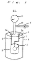
- FIGURE 1 is a schematic perspective view of test cell C1 (other cells also have the same structure).
- test cell C1 comprises a disc-shaped paste electrode (PE1) 2, a cylindrical sintered nickel electrode 3 and an insulating closed container 4.
- the sintered nickel electrode 3 is held by a positive electrode lead 5 connected to the upper surface 6 of the closed container 4.
- the paste electrode 2 is held such that it is vertically positioned near the center of the hollow cylinder of the sintered nickel electrode 3, by a negative electrode lead 7 connected to the upper surface 6 of the closed container 4.
- the end each of the positive electrode lead 5 and negative electrode 7 are, penetrating the upper surface 6 of the closed container 4, exposed outwardly and connected to a positive electrode terminal 5a and negative electrode terminal 7a, respectively.
- the paste electrode 2 and the sintered nickel electrode 3 are immersed in an alkaline electrolyte solution (aqueous 30% by weight potassium hydroxide solution; not shown) contained in the closed container 4.
- an alkaline electrolyte solution aqueous 30% by weight potassium hydroxide solution; not shown
- the space above the alkaline electrolyte solution is filled with nitrogen so that a prescribed pressure is applied to the paste electrode 2.
- a relief pipe 10 equipped with a pressure gauge 8 and a relief valve 9.
- Table 1 shows hydrogen contents in reducing gas, cooling rates, average thicknesses of alloys and average thicknesses of hydride layers.
- Table 2 shows the major axis lengths of crystallites constituting the main phase of the alloys and the major axis length-to-minor axis length ratios.
- Table 1 Cell Hydrogen content (% by volume) Cooling rate (°C/sec) Average thickness of alloy ( ⁇ m) Average thickness of alloy hydride layer ( ⁇ m) C1 5 1 x 10³ 22 0.4 C2 5 1 x 10⁴ 17 0.4 C3 5 1 x 10⁵ 15 0.4 C4 1 1 x 10³ 23 0.005 C5 2 1 x 10³ 22 0.2 C6 10 1 x 10³ 24 3.2 C7 15 1 x 10³ 22 5.6 CC1 5 1 x 10² 630 0.4 CC2 0 1 x 10² 628 0 CC3 0 1 x 10³ 23 0 CC4 0 1 x 10⁴ 17 0 CC5 0 1 x 10⁵ 14 0
- Table 2 Cell Major axis length of crystallites constituting main phase ( ⁇ m); (average) Ratio of major axis length to minor axis length of crystallites constituting main phase; (average) C1 3.7 to 5.4 (4.4) 1.5 to 2.3 (2.0) C
- test cells C1 through C3 and comparison test cells CC1 through CC5 were measured to study the relationship between the cooling rate and atmosphere composition during solidification and the cycle life.
- Each of the test cells was subjected to a charge-discharge cycle test, in which one cycle consisting of charge at room temperature (25°C) and 30 mA/g for 8 hours and, after 1-hour pause, discharge at 30 mA/g to a discharge termination voltage of 1.0 V, followed by 1-hour pause.
- the number (times) of cycles by which the capacity decreases to 50% of the initial capacity was taken as the cycle life.
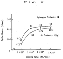
- FIGURE 2 is a graph showing the relationship between the cooling rate and atmosphere during solidification and the cycle life, with the ordinate representing the cycle number (times) and the abscissa the cooling rate (°C/sec) of hydrogen-absorbing alloys used for the test cells. It is understood from the FIGURE that test cells C1 through C3 and comparison test cell CC1, with electrodes using alloys obtained by solidifying alloy melts under a reducing atmosphere, have longer cycle lives than those of comparison test cells CC2 through CC5 with electrodes using alloys obtained by solidifying under an atmosphere of argon at the same cooling rates. This fact shows that formation of a hydride layer contributes greatly to prolongation of cycle life. Besides, comparison of test cells C1 through C3 with comparison test cell CC1 shows that at least 1 x 10³°C/sec is necessary for obtaining a long-life cell of at least 200 cycles.
- Test cells C4 through C7 were tested for cycle life in the same manner as above to study the relationship between the hydrogen content in the reducing gas used and the cycle life.
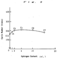
- FIGURE 3 is a graph showing the relationship between the hydrogen content in reducing gas and the cycle life, with the ordinate representing cycle number (times) and the abscissa the hydrogen content (%).
- the FIGURE also shows the cycle lives measured above of test cell C1 and comparison test cell CC3. It is understood from the FIGURE that the thickness of the hydride layer is desirably in a range of 0.01 to 3 ⁇ m in order to obtain a hydrogen-absorbing alloy electrode that hardly undergoes cycle deterioration.
- the present invention is applicable to hydrogen-absorbing alloy electrodes using alloys principally comprising these metals as electrode materials .
- arc melting furnace was used in the Examples as heating means for obtaining alloy melts
- high-frequency induction heating furnace can also be used.
- alloy component metals of Ti, Ni and Mo each commercially available simple metal substance having a purity of at least 99.9%
- the obtained mixture was placed in a copper crucible in an arc furnace with an atmosphere of an inert gas (argon) and melted by heating.
- the melt was then quenched by a single-roll method at a cooling rate of 1 x 10³°C/sec, to give flake-shaped hydrogen-absorbing alloys having a composition formula of TiNi 0.5 Mo 0.6 .
- the hydrogen-absorbing alloy was analyzed for crystal structure by X-ray diffractometry and EPMA (electron probe microanalysis) on the alloy cross-section, to prove that it had a composite phase structure comprising a main phase with bcc crystal structure and a subphase with bcc crystal structure.
- the above hydrogen-absorbing alloy was also tested by EPMA for the areal ratio in the cross-section of the subphase to the main phase, which was found to be 5%.
- This ratio value was an average of 10 measurements conducted on 10 square spots having a size of 30 ⁇ m x 30 ⁇ m selected at random from an optional cross-section of the alloy (hereinafter the same test procedure was followed for measuring areal ratio of subphase).
- an alloy paste was prepared by mixing 1 g of the hydrogen-absorbing alloy thus obtained with 0.2 g of polytetrafluoroethylene (PTFE) as a binder and 1.2 g of nickel powder as a conductive agent, and rolling the obtained mixture.
- PTFE polytetrafluoroethylene
- a prescribed amount of the alloy paste was wrapped in a nickel mesh, and the wrap was pressed into a disc-shaped paste electrode PE8 having a diameter of 20 mm.
- Preparation Example 8 was repeated except that the mixing ratio of component metals of Ti, Ni and Mo was changed, to obtain a hydrogen-absorbing alloy represented by composition formula Ti 1.2 Ni 0.5 Mo 0.5 , which was then processed into a paste electrode PE9 in the same manner.
- the areal ratio in the cross-section of subphase to main phase was 10%.
- the alloy had a crystal structure comprising a main phase having bcc crystal structure, a subphase having bcc crystal structure and a subphase having hcp crystal structure.
- Preparation Example 8 was repeated except that the mixing ratio of component metals of Ti, Ni and Mo was changed, to obtain a hydrogen-absorbing alloy represented by composition formula TiNi 0.4 Mo 0.7 , which was then processed into a paste electrode PE10 in the same manner.
- the areal ratio in the cross-section of subphase to main phase was 14%.
- the alloy had a crystal structure comprising a main phase having bcc crystal structure and a subphase having bcc crystal structure.
- Preparation Example 8 was repeated except that the mixing ratio of component metals of Ti, Ni and Mo was changed, to obtain a hydrogen-absorbing alloy represented by composition formula TiNi 0.3 Mo 0.4 , which was then processed into a paste electrode PE11 in the same manner.
- the areal ratio in the cross-section of subphase to main phase was 18%.
- the alloy had a crystal structure comprising a main phase having bcc crystal structure, a subphase having bcc crystal structure and a subphase having hcp crystal structure.
- Preparation Example 8 was repeated except that the mixing ratio of component metals of Ti, Ni and Mo was changed, to obtain a hydrogen-absorbing alloy represented by composition formula Ti 1.2 Ni 0.5 Mo 0.4 , which was then processed into a comparison paste electrode CPE6 in the same manner.
- the areal ratio in the cross-section of subphase to main phase was 22%.
- the alloy had a crystal structure comprising a main phase having bcc crystal structure and a subphase having bcc crystal structure.
- Preparation Example 8 was repeated except that the mixing ratio of component metals of Ti, Ni and Mo was changed and that the cooling rate was changed to 1 x 10²°C/sec, to obtain a hydrogen-absorbing alloy represented by composition formula TiNi 0.5 Mo 0.7 , which was then processed into a comparison paste electrode CPE7 in the same manner.
- the areal ratio in the cross-section of subphase to main phase was 28%.
- the alloy had a crystal structure comprising a main phase having bcc crystal structure and a subphase having bcc crystal structure.
- Preparation Example 8 was repeated except that the mixing ratio of component metals of Ti, Ni and Mo was changed and that the cooling rate was changed to 1 x 10²°C/sec, to obtain a hydrogen-absorbing alloy represented by composition formula TiNi 0.4 Mo 0.7 , which was then processed into a comparison paste electrode CPE8 in the same manner.
- the areal ratio in the cross-section of subphase to main phase was 34%.
- the alloy had a crystal structure comprising a main phase having bcc crystal structure, a subphase having bcc structure and a subphase having hcp crystal structure.
- Preparation Example 8 was repeated except that the mixing ratio of component metals of Ti, Ni and Mo was changed, to obtain a hydrogen-absorbing alloy represented by composition formula TiNi 0.4 Mo 0.8 , which was then processed into a comparison paste electrode CPE9 in the same manner.
- the areal ratio in the cross-section of subphase to main phase was 23%.
- the alloy had a crystal structure comprising a main phase having bcc crystal structure and a subphase having bcc crystal structure.
- Preparation Example 8 was repeated except that a melt of equimolar amounts of Ti and Ni was solidified at a cooling rate of 1 x 10³°C/sec, to obtain a hydrogen-absorbing alloy represented by composition formula TiNi, which was then processed into a comparison paste electrode CPE10 in the same manner.
- the areal ratio in the cross-section of subphase to main phase was 2%.
- the alloy had a crystal structure comprising a main phase having bcc crystal structure, a subphase having bcc crystal structure and a subphase having hcp crystal structure.
- Preparation Example 8 was repeated except that a melt of equimolar amounts of Ti and Mo was solidified at a cooling rate of 1 x 10³°C/sec, to obtain a hydrogen-absorbing alloy represented by composition formula TiMo, which was then processed into a comparison paste electrode CPE11 in the same manner.
- the areal ratio in the cross-section of subphase to main phase was 4%.
- the alloy had a crystal structure comprising a main phase having bcc crystal structure, a subphase having bcc crystal structure and a subphase having bcc crystal structure.
- Preparation Example 8 was repeated except that a melt of equimolar amounts of Ni and Mo was solidified at a cooling rate of 1 x 10³°C/sec, to obtain a hydrogen-absorbing alloy represented by composition formula NiMo, which was then processed into a comparison paste electrode CPE12 in the same manner.
- the areal ratio in the cross-section of subphase to main phase was 7%.
- the alloy had a crystal structure comprising a main phase having bcc crystal structure and a subphase having bcc crystal structure.
- the above paste electrodes PE8 through PE11 and the comparison paste electrodes CPE6 through CPE12 were used and test cells C8 through C11 and comparison test cells CC6 through CC12 were prepared correspondingly.
- Table 3 shows, for the hydrogen-absorbing alloys used for the test cells, their alloy compositions, main phase structures, subphase structures and average areal ratios of subphase to main phase in the alloy cross-section.
- Table 3 Test cell Alloy composition Main phase structure Subphase structure Areal ratio of subphase (%) Cycle life (times)
- the cycle life of each test cell was measured.
- the test cells were subjected to a charge-discharge cycle test, in which one cycle consisting of charge at room temperature (25°C) and 30 mA/g for 8 hours and, after 1-hour pause, discharge at 30 mA/g to a discharge termination voltage of 1.0 V, followed by 1-hour pause.
- the number (times) of cycles by which the capacity decreases to 50% of the initial capacity was taken as the cycle life.
- the results are shown in FIGURE 4 and Table 3.
- test cells C8 through C11 using alloys having a composite phase structure comprising a main phase and a subphase(s), with the areal ratio of subphase to main phase in the alloy cross-section being 5 to 20%, have far longer cycle lives than those of comparison test cells CC6 through CC9, which, while having a composite phase structure, use alloys with the areal ratio of subphase to main phase deviating from the above range, and than those of comparison test cells CC10 through CC12 with similar composite structure but having different alloy compositions.
- comparison test cell CC12 using an NiMo alloy with an areal ratio of subpahse to main phase in the cross-section of 7%, has a very short cycle life, it is understood that significance of restricting the areal ratio of subphase to main phase in the alloy cross-section to 5 to 20% is not applicable to hydrogen-absorbing alloys in general.
- Preparation Examples 8 through 11 While an example as a hydrogen-absorbing alloy of Ti-Mo-Ni 3-element alloy is mentioned in Preparation Examples 8 through 11, the present invention is applicable to hydrogen-absorbing alloy electrodes using electrode materials of alloys principally comprising these metals. Further in Preparation Examples 8 through 11, while an advantageous means for practicing the present invention of solidification by quenching was explained as an example, any other process is applicable insofar as it can effectively produce an alloy with the subphase-to-main phase ratio being in the range specified in the present invention.
- An alloy paste was prepared by mixing 1 g of the hydrogen-absorbing alloy obtained above with 0.2 g of polytetrafluoroethylene (PTFE) as a binder and 1.2 g of Nickel powder as a conductive agent, and rolling the obtained mixture.
- PTFE polytetrafluoroethylene
- each of the alloy paste was wrapped in a nickel mesh, and the wrap was pressed into a disc-shaped paste electrode PE12 having a diameter of 20 mm.
- Preparation Example 12 was repeated except that the cooling rate was changed from 1 x 10³°C/sec to 1 x 10⁴°C/sec, to obtain a paste electrode PE13.
- Crystallites constituting the main phase of the hydrogen-absorbing alloy powder used there had a major axis length (a) and major-minor ratio (a/b) of 1.1 to 2.0 ⁇ m (average: 1.5 ⁇ m) and 1.1 to 1.8 (average: 1.5), respectively.
- Preparation Example 12 was repeated except that the cooling rate was changed from 1 x 10³°C/sec to 1 x 10⁵°C/sec, to obtain a paste electrode PE14.
- Crystallites constituting the main phase of the hydrogen-absorbing alloy powder used there had a major axis length (a) and major-minor ratio (a/b) were 0.8 to 1.2 ⁇ m (average: 1.0 ⁇ m) and 1.1 to 1.6 (average: 1.4), respectively.
- each of alloy component metals of Ti, Zr, Mo and Ni was weighed and mixed together.
- the obtained mixture was placed in a copper crucible in an arc furnace with an atmosphere of an inert gas (argon) and melted by heating.
- the melt was then cooled by a single-roll process at a cooling rate of 1 x 10³°C/sec, to give an hydrogen-absorbing alloy having a composition formula of Ti 0.8 Zr 0.2 Mo 0.5 Ni 0.5 .
- Crystallites constituting the main phase of the hydrogen-absorbing alloy obtained had a major axis length (a) and major-minor ratio (a/b) of 3.7 to 5.5 ⁇ m (average: 4.6 ⁇ m) and 1.2 to 3.0 (average: 2.2), respectively.
- the hydrogen-absorbing alloy was used to prepare a paste electrode PE15 in the same manner as in Preparation Example 12.
- Preparation Example 15 was repeated except that the cooling rate was changed from 1 x 10³°C/sec to 1 x 10⁵°C/sec, to obtain a paste electrode PE16.
- Crystallites constituting the main phase of the hydrogen-absorbing alloy powder used there had a major axis length (a) and major-minor ratio (a/b) of 0.9 to 1.3 ⁇ m (average: 1.2 ⁇ m) and 1.1 to 1.5 (average: 1.3), respectively.
- Preparation Example 12 was repeated except that the cooling rate was changed from 1 x 10³°C/sec to 1 x 10²°C/sec, to obtain a comparison paste electrode CPE13.
- Crystallites constituting the main phase of the hydrogen-absorbing alloy powder used there had a major axis length (a) and major-minor ratio (a/b) of 22 to 45 ⁇ m (average: 30 ⁇ m) and 1.6 to 3.7 (average: 3.2), respectively.
- Preparation Example 15 was repeated except that the cooling rate was changed from 1 x 10³°C/sec to 1 x 10²°C/sec, to obtain a comparison paste electrode CPE14.
- Crystallites constituting the main phase of the hydrogen-absorbing alloy powder used there had a major axis length (a) and major-minor ratio (a/b) of 21 to 46 ⁇ m (average: 33 ⁇ m) and 1.2 to 4.1 (average: 3.5), respectively.
- alloy component metals of Ti, Zr and Mo each commercially available simple metal substance having a purity of at least 99.9%
- the obtained mixture was placed in a copper crucible in an arc furnace with an atmosphere of an inert gas (argon) and melted by heating.
- the melt was then cooled by a single-roll process at a cooling rate of 1 x 10²°C/sec, to give an hydrogen-absorbing alloy having a composition formula of Ti 0.8 Zr 0.2 Mo.
- Crystallites constituting the main phase of the hydrogen-absorbing alloy obtained had a major axis length (a) and major-minor ratio (a/b) of 25 to 45 ⁇ m (average: 33 ⁇ m) and 1.4 to 3.9 (average: 3.2), respectively.
- the hydrogen-absorbing alloy was used to prepare a comparison paste electrode CPE15 in the same manner as in Preparation Example 12.
- Comparative Preparation Example 15 was repeated except that the cooling rate was changed from 1 x 10²°C/sec to 1 x 10³°C/sec, to obtain a comparison paste electrode CPE16.
- Crystallites constituting the main phase of the hydrogen-absorbing alloy powder used there had a major axis length (a) and major-minor ratio (a/b) were 3.5 to 5.8 ⁇ m (average: 4.5 ⁇ m) and 1.3 to 2.7 (average: 2.0), respectively.
- Preparation Example 15 was repeated except that the cooling rate was changed from 1 x 10²°C/sec to 1 x 10⁵°C/sec, to obtain a comparison paste electrode CPE17.
- Crystallites constituting the main phase of the hydrogen-absorbing alloy powder used there had a major axis length (a) and major-minor ratio (a/b) of 1.1 to 1.5 ⁇ m (average: 1.3 ⁇ m) and 1.1 to 1.5 (average: 1.3), respectively.
- FIGURE 5 through FIGURE 7 are graphs separately showing, by alloy types, the relationship between the cooling rate for alloy melt and the major axis length of crystallites constituting the main phase of the obtained hydrogen-absorbing alloy.
- the ordinate represents the major axis length (a) in ⁇ m and the abscissa the cooling rate (°C/sec). It is understood from these graphs that the major axis length (a) shortens and its diversion (distribution) decreases with increasing cooling rate, regardless of alloy type.
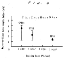
- FIGURE 8 through FIGURE 10 are graphs separately showing, by alloy types, the relationship between the cooling rate for alloy melt and the major-to-minor axis length ratio of crystallites constituting the main phase of the obtained hydrogen-absorbing alloy.
- the ordinate represents the major-to-minor ratio (a/b) and the abscissa the cooling rate (°C/sec). It is understood from these graphs that the major-to-minor ratio (a/b) and its diversion (distribution) both decrease with increasing cooling rate, regardless of alloy type.
- positions on the ordinate for ⁇ , ⁇ and ⁇ show the major axis length (a) or the major-to-minor ratio (a/b) that are averages of measurements on 20 specimens.
- the above paste electrodes PE12 through PE16 and the comparison paste electrodes CPE13 through CPE17 were used and test cells C12 through C16 and comparison test cells CC13 through CC17 were prepared correspondingly.
- the cycle life of each test cell was measured.
- the test cells were subjected to a charge-discharge cycle test, in which one cycle consisting of charge at room temperature (25°C) and 30 mA/g for 8 hours and, after 1-hour pause, discharge at 30 mA/g to a discharge termination voltage of 1.0 V, followed by 1-hour pause.
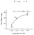
- FIGURES 11 through 13 are graphs showing the cycle lives of test cells, with the ordinate representing the cycle number (times) and the abscissa the cooling rate (°C/sec).
- test cells C12 through C16 using Ti-Mo-Ni or Ti-Zr-Mo-Ni hydrogen-absorbing alloys obtained by solidification by quenching at a cooling rate of at least 1 x 10³°C/sec and comprising crystallites having a major axis length (a) of 0.8 to 6 ⁇ m and a major-to-minor ratio (a/b) of not more than 3 have longer cycle lives than those of comparison test cells CC13 and CC14, using a Ti-Mo-Ni 3-element alloy and a Ti-Zr-Mo-Ni 4-element alloy respectively which comprised crystallites having a major axis length (a) and a major to-minor ratio each deviating from the above range.
Landscapes
- Chemical & Material Sciences (AREA)
- Chemical Kinetics & Catalysis (AREA)
- Electrochemistry (AREA)
- General Chemical & Material Sciences (AREA)
- Battery Electrode And Active Subsutance (AREA)
Applications Claiming Priority (12)
| Application Number | Priority Date | Filing Date | Title |
|---|---|---|---|
| JP12516793 | 1993-04-28 | ||
| JP125167/93 | 1993-04-28 | ||
| JP5125169A JPH06310139A (ja) | 1993-04-28 | 1993-04-28 | 水素吸蔵合金電極 |
| JP12516893 | 1993-04-28 | ||
| JP12517093 | 1993-04-28 | ||
| JP5125168A JPH06310138A (ja) | 1993-04-28 | 1993-04-28 | 水素吸蔵合金電極 |
| JP12516793A JP3291356B2 (ja) | 1993-04-28 | 1993-04-28 | 水素吸蔵合金電極 |
| JP125168/93 | 1993-04-28 | ||
| JP125169/93 | 1993-04-28 | ||
| JP12516993 | 1993-04-28 | ||
| JP125170/93 | 1993-04-28 | ||
| JP5125170A JPH06310140A (ja) | 1993-04-28 | 1993-04-28 | 水素吸蔵合金電極 |
Publications (3)
| Publication Number | Publication Date |
|---|---|
| EP0622860A2 true EP0622860A2 (fr) | 1994-11-02 |
| EP0622860A3 EP0622860A3 (fr) | 1995-03-01 |
| EP0622860B1 EP0622860B1 (fr) | 2005-08-03 |
Family
ID=27471087
Family Applications (1)
| Application Number | Title | Priority Date | Filing Date |
|---|---|---|---|
| EP94106597A Expired - Lifetime EP0622860B1 (fr) | 1993-04-28 | 1994-04-27 | Electrode en alliage absorbant l'hydrogène |
Country Status (3)
| Country | Link |
|---|---|
| US (1) | US5441826A (fr) |
| EP (1) | EP0622860B1 (fr) |
| DE (1) | DE69434444T2 (fr) |
Cited By (4)
| Publication number | Priority date | Publication date | Assignee | Title |
|---|---|---|---|---|
| EP0714143A1 (fr) * | 1994-11-25 | 1996-05-29 | Sanyo Electric Co. Ltd | Electrode en alliage absorbant l'hydrogène pour piles alcalines à hydrure métallique et procédé de fabrication |
| EP0806803A1 (fr) * | 1996-05-09 | 1997-11-12 | Mitsubishi Materials Corporation | Alliage à occlusion d'hydrogene, procédé pour sa préparation et électrode |
| US6632136B2 (en) * | 2001-06-05 | 2003-10-14 | Deere & Company | Remote adjustment mechanism for a combine harvester cleaning element |
| CN109461889A (zh) * | 2018-10-09 | 2019-03-12 | 天能电池集团(安徽)有限公司 | 一种电池制造用固化室辅助加热管道 |
Families Citing this family (2)
| Publication number | Priority date | Publication date | Assignee | Title |
|---|---|---|---|---|
| JPH09209065A (ja) * | 1994-11-07 | 1997-08-12 | Santoku Kinzoku Kogyo Kk | 時効析出型希土類金属−ニッケル系合金、その製造法及びニッケル水素2次電池用負極 |
| US5932372A (en) * | 1997-01-02 | 1999-08-03 | Lightyear Technologies Inc. | Composite materials, processes for manufacturing the composites, composite electrode, hydrogen occluding composite, and electrochemical cell utilizing the composite |
Family Cites Families (12)
| Publication number | Priority date | Publication date | Assignee | Title |
|---|---|---|---|---|
| CA1123816A (fr) * | 1978-02-06 | 1982-05-18 | Harold M. Simons | Metal granule et active, transforme en hydrure |
| US4431561A (en) * | 1982-04-28 | 1984-02-14 | Energy Conversion Devices, Inc. | Hydrogen storage materials and method of making same |
| US4551400A (en) * | 1984-04-18 | 1985-11-05 | Energy Conversion Devices, Inc. | Hydrogen storage materials and methods of sizing and preparing the same for electrochemical applications |
| US4923770A (en) * | 1985-03-29 | 1990-05-08 | The Standard Oil Company | Amorphous metal alloy compositions for reversible hydrogen storage and electrodes made therefrom |
| US4728586A (en) * | 1986-12-29 | 1988-03-01 | Energy Conversion Devices, Inc. | Enhanced charge retention electrochemical hydrogen storage alloys and an enhanced charge retention electrochemical cell |
| JPH0650634B2 (ja) * | 1987-08-19 | 1994-06-29 | 松下電器産業株式会社 | 水素吸蔵電極 |
| JPH0763007B2 (ja) * | 1987-05-22 | 1995-07-05 | 松下電器産業株式会社 | 水素吸蔵電極の製造法 |
| US5268143A (en) * | 1988-06-28 | 1993-12-07 | Matsushita Electric Industrial Co., Ltd. | Method of producing hydrogen-storing alloy from a zirconium-tin starting material |
| JP2980328B2 (ja) * | 1989-09-29 | 1999-11-22 | 株式会社東芝 | 電池用水素吸蔵合金、その製造方法及びニッケル水素二次電池 |
| US5104617A (en) * | 1990-04-26 | 1992-04-14 | Energy Conversion Devices, Inc. | Catalytic hydrogen storage electrode materials for use in electrochemical cells and electrochemical cells incorporating the materials |
| US5149383A (en) * | 1990-04-03 | 1992-09-22 | Matsushita Electric Industrial Co., Ltd. | Hydrogen storage alloy electrode |
| US5135589A (en) * | 1990-04-16 | 1992-08-04 | Fetcenko Michael A | Metastable hydrogen storage alloy material |
-
1994
- 1994-01-31 US US08/189,172 patent/US5441826A/en not_active Expired - Lifetime
- 1994-04-27 DE DE69434444T patent/DE69434444T2/de not_active Expired - Fee Related
- 1994-04-27 EP EP94106597A patent/EP0622860B1/fr not_active Expired - Lifetime
Cited By (6)
| Publication number | Priority date | Publication date | Assignee | Title |
|---|---|---|---|---|
| EP0714143A1 (fr) * | 1994-11-25 | 1996-05-29 | Sanyo Electric Co. Ltd | Electrode en alliage absorbant l'hydrogène pour piles alcalines à hydrure métallique et procédé de fabrication |
| US5629000A (en) * | 1994-11-25 | 1997-05-13 | Sanyo Electric Co., Ltd. | Hydrogen-absorbing alloy electrode for metal hydride alkaline batteries and process for producing the same |
| EP0806803A1 (fr) * | 1996-05-09 | 1997-11-12 | Mitsubishi Materials Corporation | Alliage à occlusion d'hydrogene, procédé pour sa préparation et électrode |
| US5900334A (en) * | 1996-05-09 | 1999-05-04 | Mitsubishi Materials Corporation | Hydrogen occluding alloy |
| US6632136B2 (en) * | 2001-06-05 | 2003-10-14 | Deere & Company | Remote adjustment mechanism for a combine harvester cleaning element |
| CN109461889A (zh) * | 2018-10-09 | 2019-03-12 | 天能电池集团(安徽)有限公司 | 一种电池制造用固化室辅助加热管道 |
Also Published As
| Publication number | Publication date |
|---|---|
| DE69434444D1 (de) | 2005-09-08 |
| US5441826A (en) | 1995-08-15 |
| EP0622860B1 (fr) | 2005-08-03 |
| EP0622860A3 (fr) | 1995-03-01 |
| DE69434444T2 (de) | 2006-01-05 |
Similar Documents
| Publication | Publication Date | Title |
|---|---|---|
| EP0420669B1 (fr) | Cellule secondaire à nickel-hydrure métallique | |
| EP2595223B1 (fr) | Matériau d'électrode négative pour batteries d'ion au lithium | |
| EP0867956B1 (fr) | Electrode en alliage emmagasinant l'hydrogène | |
| EP0609609B1 (fr) | Procédé de fabrication d'un alliage absorbant l'hydrogène pour électrode négative | |
| EP2813588B1 (fr) | Poudre d'alliage d'absorption d'hydrogène, électrode négative et cellule secondaire nickel-hydrogène | |
| EP0622860B1 (fr) | Electrode en alliage absorbant l'hydrogène | |
| EP2653576B1 (fr) | Poudre d'alliage absorbant l'hydrogène, électrode négative et batterie secondaire nickel-hydrogène | |
| EP0714143B1 (fr) | Electrode en alliage absorbant l'hydrogène pour piles alcalines à hydrure métallique et procédé de fabrication | |
| DE19639440C2 (de) | Wasserstoff absorbierende Legierung für eine Batterie und Verwendung der Legierung in Sekundär-Nickel-Metallhydrid-Batterien | |
| JPH03191040A (ja) | 水素吸蔵合金電極 | |
| US5358800A (en) | Active material of hydrogen storage alloy electrode | |
| US5688341A (en) | Hydrogen-absorbing alloy electrode and method for evaluating hydrogen-absorbing alloys for electrode | |
| EP0867957B1 (fr) | Electrode négative pour accumulateur alcalin | |
| JPH11144728A (ja) | 水素吸蔵合金電極 | |
| JP3981423B2 (ja) | 電池用水素吸蔵合金およびニッケル水素二次電池 | |
| JP3301792B2 (ja) | 水素吸蔵合金電極 | |
| JP3291356B2 (ja) | 水素吸蔵合金電極 | |
| JPH0945322A (ja) | 水素吸蔵合金およびそれを用いた水素吸蔵合金電極 | |
| JPH0949034A (ja) | 水素吸蔵合金の製造方法 | |
| JP3432866B2 (ja) | アルカリ蓄電池用の水素吸蔵合金電極 | |
| JP2002516023A (ja) | 再充電可能な電気化学電池に使用するab5型の水素貯蔵合金、およびその製造法 | |
| JPH1027605A (ja) | 水素吸蔵電極 | |
| JP2000087102A (ja) | 水素吸蔵合金粉末及びこれを用いた電極 | |
| JPH06111817A (ja) | 金属・水素化物二次電池 | |
| JPH06310140A (ja) | 水素吸蔵合金電極 |
Legal Events
| Date | Code | Title | Description |
|---|---|---|---|
| PUAI | Public reference made under article 153(3) epc to a published international application that has entered the european phase |
Free format text: ORIGINAL CODE: 0009012 |
|
| AK | Designated contracting states |
Kind code of ref document: A2 Designated state(s): CH DE FR GB LI |
|
| PUAL | Search report despatched |
Free format text: ORIGINAL CODE: 0009013 |
|
| AK | Designated contracting states |
Kind code of ref document: A3 Designated state(s): CH DE FR GB LI |
|
| 17P | Request for examination filed |
Effective date: 19950321 |
|
| GRAP | Despatch of communication of intention to grant a patent |
Free format text: ORIGINAL CODE: EPIDOSNIGR1 |
|
| GRAS | Grant fee paid |
Free format text: ORIGINAL CODE: EPIDOSNIGR3 |
|
| GRAA | (expected) grant |
Free format text: ORIGINAL CODE: 0009210 |
|
| AK | Designated contracting states |
Kind code of ref document: B1 Designated state(s): CH DE FR GB LI |
|
| PG25 | Lapsed in a contracting state [announced via postgrant information from national office to epo] |
Ref country code: LI Free format text: LAPSE BECAUSE OF FAILURE TO SUBMIT A TRANSLATION OF THE DESCRIPTION OR TO PAY THE FEE WITHIN THE PRESCRIBED TIME-LIMIT Effective date: 20050803 Ref country code: CH Free format text: LAPSE BECAUSE OF FAILURE TO SUBMIT A TRANSLATION OF THE DESCRIPTION OR TO PAY THE FEE WITHIN THE PRESCRIBED TIME-LIMIT Effective date: 20050803 |
|
| REG | Reference to a national code |
Ref country code: GB Ref legal event code: FG4D |
|
| REG | Reference to a national code |
Ref country code: CH Ref legal event code: EP |
|
| REF | Corresponds to: |
Ref document number: 69434444 Country of ref document: DE Date of ref document: 20050908 Kind code of ref document: P |
|
| REG | Reference to a national code |
Ref country code: CH Ref legal event code: PL |
|
| ET | Fr: translation filed | ||
| PLBE | No opposition filed within time limit |
Free format text: ORIGINAL CODE: 0009261 |
|
| STAA | Information on the status of an ep patent application or granted ep patent |
Free format text: STATUS: NO OPPOSITION FILED WITHIN TIME LIMIT |
|
| 26N | No opposition filed |
Effective date: 20060504 |
|
| PGFP | Annual fee paid to national office [announced via postgrant information from national office to epo] |
Ref country code: FR Payment date: 20080312 Year of fee payment: 15 Ref country code: DE Payment date: 20080502 Year of fee payment: 15 |
|
| PGFP | Annual fee paid to national office [announced via postgrant information from national office to epo] |
Ref country code: GB Payment date: 20080430 Year of fee payment: 15 |
|
| GBPC | Gb: european patent ceased through non-payment of renewal fee |
Effective date: 20090427 |
|
| REG | Reference to a national code |
Ref country code: FR Ref legal event code: ST Effective date: 20091231 |
|
| PG25 | Lapsed in a contracting state [announced via postgrant information from national office to epo] |
Ref country code: DE Free format text: LAPSE BECAUSE OF NON-PAYMENT OF DUE FEES Effective date: 20091103 |
|
| PG25 | Lapsed in a contracting state [announced via postgrant information from national office to epo] |
Ref country code: GB Free format text: LAPSE BECAUSE OF NON-PAYMENT OF DUE FEES Effective date: 20090427 Ref country code: FR Free format text: LAPSE BECAUSE OF NON-PAYMENT OF DUE FEES Effective date: 20091222 |