EP0622958B1 - Echtzeitdatensender/-empfänger - Google Patents
Echtzeitdatensender/-empfänger Download PDFInfo
- Publication number
- EP0622958B1 EP0622958B1 EP94106493A EP94106493A EP0622958B1 EP 0622958 B1 EP0622958 B1 EP 0622958B1 EP 94106493 A EP94106493 A EP 94106493A EP 94106493 A EP94106493 A EP 94106493A EP 0622958 B1 EP0622958 B1 EP 0622958B1
- Authority
- EP
- European Patent Office
- Prior art keywords
- data
- frame count
- frame
- motion image
- real
- Prior art date
- Legal status (The legal status is an assumption and is not a legal conclusion. Google has not performed a legal analysis and makes no representation as to the accuracy of the status listed.)
- Expired - Lifetime
Links
Images

Classifications
-
- H—ELECTRICITY
- H04—ELECTRIC COMMUNICATION TECHNIQUE
- H04N—PICTORIAL COMMUNICATION, e.g. TELEVISION
- H04N7/00—Television systems
- H04N7/12—Systems in which the television signal is transmitted via one channel or a plurality of parallel channels, the bandwidth of each channel being less than the bandwidth of the television signal
-
- H—ELECTRICITY
- H04—ELECTRIC COMMUNICATION TECHNIQUE
- H04N—PICTORIAL COMMUNICATION, e.g. TELEVISION
- H04N21/00—Selective content distribution, e.g. interactive television or video on demand [VOD]
- H04N21/40—Client devices specifically adapted for the reception of or interaction with content, e.g. set-top-box [STB]; Operations thereof
- H04N21/43—Processing of content or additional data, e.g. demultiplexing additional data from a digital video stream; Elementary client operations, e.g. monitoring of home network or synchronising decoder's clock; Client middleware
- H04N21/4302—Content synchronisation processes, e.g. decoder synchronisation
-
- H—ELECTRICITY
- H04—ELECTRIC COMMUNICATION TECHNIQUE
- H04N—PICTORIAL COMMUNICATION, e.g. TELEVISION
- H04N21/00—Selective content distribution, e.g. interactive television or video on demand [VOD]
- H04N21/20—Servers specifically adapted for the distribution of content, e.g. VOD servers; Operations thereof
- H04N21/23—Processing of content or additional data; Elementary server operations; Server middleware
- H04N21/242—Synchronisation processes, e.g. processing of PCR [Programme Clock References]
-
- H—ELECTRICITY
- H04—ELECTRIC COMMUNICATION TECHNIQUE
- H04N—PICTORIAL COMMUNICATION, e.g. TELEVISION
- H04N21/00—Selective content distribution, e.g. interactive television or video on demand [VOD]
- H04N21/60—Network structure or processes for video distribution between server and client or between remote clients; Control signalling between clients, server and network components; Transmission of management data between server and client, e.g. sending from server to client commands for recording incoming content stream; Communication details between server and client
- H04N21/63—Control signaling related to video distribution between client, server and network components; Network processes for video distribution between server and clients or between remote clients, e.g. transmitting basic layer and enhancement layers over different transmission paths, setting up a peer-to-peer communication via Internet between remote STB's; Communication protocols; Addressing
- H04N21/643—Communication protocols
- H04N21/6437—Real-time Transport Protocol [RTP]
-
- H—ELECTRICITY
- H04—ELECTRIC COMMUNICATION TECHNIQUE
- H04N—PICTORIAL COMMUNICATION, e.g. TELEVISION
- H04N7/00—Television systems
- H04N7/24—Systems for the transmission of television signals using pulse code modulation
- H04N7/52—Systems for transmission of a pulse code modulated video signal with one or more other pulse code modulated signals, e.g. an audio signal or a synchronizing signal
- H04N7/54—Systems for transmission of a pulse code modulated video signal with one or more other pulse code modulated signals, e.g. an audio signal or a synchronizing signal the signals being synchronous
- H04N7/56—Synchronising systems therefor
Definitions
- the present invention relates to a data transmitter apparatus and a data receiver apparatus between which desired data of e.g. motion image is transferred at real time.
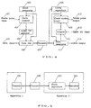
- FIG. 5 shows one such prior art for transmitting motion image data through a digital transmission channel, in which a transmitter 501 in a data transmitter apparatus 1 is coupled by a digital transmission channel 502 to a data receiver apparatus 2.
- the data receiver apparatus 2 comprises a clock reproducer 503 and a receiver 504.
- the motion image data in digital form is transmitted as a stream of bits from the transmitter apparatus 1 via the transmission channel 502 to the clock reproducer 503 in the receiver apparatus 2.
- a clock signal synchronized with the bit stream is reproduced from the transmitted data.
- the transmitted or input data is processed by the receiver 504 with synchronization with the clock signal to reconstruct an original image.
- any motion image data can be transferred through the digital transmission channel.
- the processing of the input image data at the receiver apparatus 2 shown in Fig. 5 is controlled by the clock signal which is synchronous with a clock signal for data transmission through the transmission channel 502. More particularly, a frame synchronizing signal for reproducing the motion image is timed with the transmission clock signal. Accordingly, a frame synchronizing signal at the transmitter apparatus 1 has to be synchronous with the transmission clock signal.
- the transmission channel 502 When the transmission channel 502 is connected to a plurality of asynchronous motion image data output apparatuses, its clock signal can be synchronized with only one of the apparatuses thus allowing the remaining apparatuses not to be simultaneously operated.
- a real time data transmitter and a real-time data receiver according to the invention are respectively defined by claim 1 and 6.
- Advantageous modifications are defined by the dependent claims.
- Fig. 1 shows a block diagram of a data transmitter and receiver system comprising a data transmitter apparatus and a data receiver apparatus according to the present invention. As shown, there are provided a motion image input 101, an encoder 102, a transmitter 103, a transmission channel 104, a receiver 105, a decoder 106, and a motion image output 107.
- a motion image data fed to the motion image input 101 is supplied to the encoder 102 where it is encoded to coded digital form.
- the coded motion image data is transferred along with frame period information for the motion image data through the transmission channel 104.
- the coded motion image data is separated from the frame period information and fed to the decoder 106.
- the frame period information is processed in the receiver 105 reproducing a frame pulse signal.
- the decoder 106 decodes the coded motion image data using the frame pulse signal to reconstruct the original motion image data which is further transmitted from the motion image output 107.
- Fig. 2 is a block diagram showing a first embodiment of a transmitter and a receiver. As shown, there are provided a frame pulse input 201, a data input 202, a clock generator 203, a transmitter clock counter 204, a data mixer 205, a transmission channel 206, a clock reproducer 207, a receiver clock counter 208, a data separator 209, a frame pulse output 210, and a data output 211. More specifically, the left to the transmission channel 206 in Fig. 2 comprises the transmitter in the transmitter apparatus and the right is the receiver in the receiver apparatus.
- a frame pulse indicating the start time of a motion image frame is fed from the frame pulse input 201 to the clock counter 204 where a count is updated by a transmission clock signal emitted from the clock generator 203 upon detecting the input of the frame pulse. More particularly, the input period of the frame pulse is defined by a number of transmission clock pulses which is referred to a frame count.
- the frame count is merged at the data mixer 205 with the motion image data supplied from the motion image input 202.
- a resultant stream of bits from the data mixer 205 is transferred through the transmission channel 205 as synchronized with the transmission clock signal emitted from the clock generator 203.
- the bit stream fed from the transmission channel 205 to the data receiver apparatus of the first embodiment is subjected to the clock reproducer 207 for separation and reconstruction of the transmission clock signal which is then sent to the data separator 209.
- the data separator 209 the motion image data and the frame count are separated from each other using the transmission clock signal.
- the motion image data is transmitted directly to the data output 211 while the frame count is fed to the receiver clock counter 208 where the period of the frame pulse is reproduced by counting the frame count with the transmission clock signal.
- the reproduced frame pulse is then delivered from the frame pulse output 210 in synchronization with the motion image data from the data output 211.
- the period of a frame determined in the transmitter can be restored at the receiver.
- the processing of the motion image data needs not to be synchronous with the transmission clock signal employed for data transmission.
- any motion image data asynchronous with the transmission clock signal can be transmitted with equal success.
- a plurality of asynchronous motion image data signals will be transmitted simultaneously.
- Fig. 3 is a block diagram of a transmitter and a receiver of a second embodiment. As shown, there are provided a frame pulse input 301, a reference input 302, a data input 303, a clock generator 304, a transmitter clock counter 305, a subtractor 306, a data mixer 307, a transmission channel 308, a clock reproducer 309, a receiver clock counter 310, an adder 311, a data separator 312, a frame pulse output 313, a reference input 314, and a data output 315.
- the left to the transmission channel 308 in Fig. 3 comprises the transmitter in the transmitter apparatus and the right is the receiver in the receiver apparatus.
- a frame pulse indicating the start time of a frame in a motion image data is fed from the frame pulse input 301 in Fig. 3 to the clock counter 305.
- the clock counter 305 counts the duration of the frame pulse using a transmission clock signal emitted from the clock generator 304, thus producing a frame count.
- the frame count is transmitted to the subtractor 306 where it is reduced by a reference number supplied from the reference input 302 to calculate a difference.
- the difference is merged at the data mixer 307 with the motion image data supplied from the data input 303.
- a resultant stream of bits from the data mixer 307 is delivered to the transmission channel 308 in synchronization with the transmission clock signal emitted from the clock generator 304.
- the bit stream fed from the transmission channel 308 to the data receiver apparatus of the second embodiment is subjected to the clock reproducer 309 for separation and reconstruction of the transmission clock signal which is then sent to the data separator 312.
- the transmission clock signal is used to separate the motion image data from the difference.
- the motion image data is transmitted directly to the data output 315 while the difference is fed to the adder 311 where it is added with the reference number supplied from the reference input 314 to reproduce the frame count.
- the reproduced frame count is then transferred to the receiver clock counter 310 where it is counted using the transmission clock signal from the clock generator 309 to restore the period of the frame pulse.
- the restored frame pulse is then delivered from the frame pulse output 313 in synchronization with the motion image data from the data output 315.
- the frame count but its difference from the reference which are memorized in both the transmitter and the receiver is transmitted. It is known that the frame period of any asynchronous television signal of the existing TV system is found different by at best one percent from the reference. Therefore, as the difference between the frame count and the reference only is transmitted, the over all amount of data to be transferred for reproducing the frame period will be minimized. Also, even if the frame period is varied in length depending on its TV system, its data to be transmitted can be controlled to a uniform as is in the form of a difference from the reference.
- Fig. 4 is a block diagram of a transmitter and a receiver of a third embodiment. As shown, there are provided a frame pulse input 401, a data input 402, a clock generator 403, a transmitter clock counter 404, a lower-bit selector 405, a data mixer 406, a transmission channel 407, a clock reproducer 408, a receiver clock counter 409, a coupler 410, a data separator 411, a frame pulse output 412, an upper-bit input 413, and a data output 414.
- the left to the transmission channel 407 in Fig. 4 comprises the transmitter in the transmitter apparatus and the right is the receiver in the receiver apparatus.
- a frame pulse indicating the start time of a frame in a motion image data is fed from the frame pulse input 401 in Fig. 4 to the clock counter 404.
- the clock counter 404 counts the duration of the frame pulse using a transmission clock signal emitted from the clock generator 403, thus producing a frame count.
- the frame count is transmitted to the lower-bit selector 405 where a specific number of lower bits are selectively extracted from the entire bits of the frame count.
- the selected lower bits are merged at the data mixer 406 with bits of the motion image data supplied from the data input 402.
- a resultant stream of bits from the data mixer 406 is delivered to the transmission channel 407 in synchronization with the transmission clock signal emitted from the clock generator 403.
- the bit stream fed from the transmission channel 407 to the data receiver apparatus of the third embodiment is subjected to the clock reproducer 408 for separation and reconstruction of the transmission clock signal which is then sent to the data separator 411.
- the transmission clock signal is used to separate the bits of the motion image data from the lower bits.
- the bits of the motion image data are transmitted directly to the data output 414 while the lower bits are fed to the coupler 410 where they are coupled to the upper bits supplied from the upper-bit input 413 to reconstruct the frame count of binary form.
- the reconstructed frame count is then transferred to the receiver clock counter 409 where it is counted using the transmission clock signal from the clock generator 408 to restore the period of the frame pulse.
- the restored frame pulse is then delivered from the frame pulse output 412 in synchronization with the motion image data from the data output 414.
- the reference for the frame period may be a product of a simple integer and a power of 2, which permits the circuitry arrangement to be facilitated.
- the reference of binary form is expressed its upper bits as a binary number and its lower bits as 0s.
- a television signal of 525/60 or 625/50 format is transmitted through the digital transmission channel at about 30 Mbit/sec according to the present invention.
- the references for 525/60 and 625/50 formats of the frame period are predetermined respectively with a clock signal of 30 MHz as expressed by: 30 x 2 15 or 11110 000000000000000B (525/60) 36 x 2 15 or 100100 000000000000000B (625/50)
- each reference of a binary form comprises a binary number of upper bits and 0s of lower bits. Then, if the frame period is (Reference)+ ⁇ (0 ⁇ ⁇ ⁇ 2 15 ), the upper bits of the frame count (excluding 15 bits from the lower end) correspond to the upper bits of the reference. Hence, ⁇ is referred to as the difference. As the result, the frame count can be restored by substituting the lower bits (lowest 15 bits) of the reference with the difference ⁇ .
- the clock counters at both sides may be designed to count only lower bits except the upper bits for simplicity while utilizing data in the processor of motion image signals.
- the reference for the frame period may be determined as 30 x 2 15 x n for a 525/60, 1125/60 or 1050/60 television signal format and 36 x 2 15 x n for a 625/50 or 1250/50 television signal format.
- the present invention allows data of the frame period to be transmitted to a receiver at an accuracy of the transmission clock signal. Accordingly, in case that the frame period is moderate in accuracy, its data to be transmitted can considerably be reduced in amount by providing a minimum of the frame count or difference thus requiring less size of the circuitry arrangement.
- the present invention is also applicable to real-time transmission of other data than the motion image data.
- the present invention is compatible with a variety of transmission methods, frequencies, and apparatuses and may be embodied in the form of a software.
Landscapes
- Engineering & Computer Science (AREA)
- Multimedia (AREA)
- Signal Processing (AREA)
- Time-Division Multiplex Systems (AREA)
- Television Systems (AREA)
- Small-Scale Networks (AREA)
- Synchronisation In Digital Transmission Systems (AREA)
- Compression Or Coding Systems Of Tv Signals (AREA)
Claims (9)
- Echtzeitdatenübertragungsgerät zur Übertragung digitaler Bewegbilddaten (202; 303; 402) über einen digitalen Übertragungskanal (206; 308; 407) in der Form eines Bit-Stroms, der in Synchronisation mit einem Übertragungstaktsignal übertragen wird, das von einem Taktgenerator (203; 304; 403) erzeugt wird, wobei die digitalen Bewegbilddaten von einem Bildimpuls (201; 301; 401) begleitet werden, der in Intervallen eines Bildes eines Bewegbildes auftritt, gekennzeichnet durch:einen Taktzähler (204; 305; 404) zur Zählung von Takten des Übertragungstaktsignals in Abhängigkeit von dem Bildimpuls während jedem der Intervalle, um einen Bildzählwert zu erzeugen, der einen Startzeitpunkt des Bildes des Bewegbildes anzeigt; undeinen Datenmischer (205; 307; 406), der mit dem Taktzähler verbunden ist, zum Empfang der digitalen Bewegbilddaten, um eine Bildzählwertinformation, basierend auf dem Bildzählwert mit digitalen Bewegbilddaten zu mischen, um zusammengesetzte Daten zu erzeugen, wobei die zusammengesetzten Daten über den digitalen Übertragungskanal (206; 308; 407) übertragen werden.
- Echtzeitdatenübertragungsgerät nach Anspruch 1, das außerdem umfaßt:
einen Differenzgenerator (306), zur Erzeugung einer Differenz als Bildzählwertinformation zwischen dem Bildzählwert und einer Referenz (302), die dem Datenübertragungsgerät beigeordnet ist. - Echtzeitdatenübertragungsgerät nach Anspruch 1, das außerdem umfaßt:
einen Generator für untere Bits (405) zur Trennung einer bestimmten Anzahl unterer Bits als Bildzählwertinformation von dem Bildzählwert, der von dem Taktzähler (404) erzeugt wurde. - Echtzeitdatenübertragungsgerät nach einem der Ansprüche 1 bis 3, wobei der Bildzählwert, die Differenz oder die unteren Bits jeweils in ihrer Genauigkeit vor der Übertragung vermindert werden.
- Echtzeitdatenübertragungsgerät nach einem der Ansprüche 1 bis 4, wobei, wenn das Übertragungstaktsignal 30 x n MHz beträgt, wobei n ein Integer ist, eine Referenz für die Bilddauer als 30 x 215 x n für ein 525/60-, 1125/60- oder 1050/60-Fernsehsignalformat und 36 x 215 x n für ein 625/50- oder 1250/50-Fernsehsignalformat ausgedrückt wird.
- Echtzeitdatenempfangsgerät zum Empfang aus einem digitalen Übertragungskanal (206; 308; 407) von zusammengesetzten Daten in Form eines Bit-Stroms, der digitale Bewegbilddaten und Bildzählwertinformation umfaßt, zur Ausgabe der digitalen Bewegbilddaten (211; 315; 414) und des Bildzählwertes (210; 313; 412), der einen Startzeitpunkt eines Bildes eines Bewegbildes anzeigt, wobei das Gerät eine Taktwiedergewinnung (207; 309; 408) zur Wiederherstellung des Übertragungstaktsignals aus den empfangenen zusammengesetzten Daten aufweist, wobei der Bildzählwert ein Zählergebnis von Taktimpulsen darstellt, gekennzeichnet durch:einen Datentrenner (209; 312; 411) zur Trennung der Bildzählwertinformation von den zusammengesetzten Daten; undeinen Taktzähler (208; 310; 409), der mit der Taktwiedergewinnung (207; 309; 408) und dem Datentrenner (209, 310, 411) zur Taktzählung des wiederhergestellten Übertragungstaktsignals und Ausgabe des Bildimpulses zu jedem Zeitpunkt, zu dem das Zählergebnis gleich dem Wert ist, der durch den Bildzählwert angezeigt wird, verbunden ist.
- Echtzeitdatenempfangsgerät nach Anspruch 6, wobei die Bildzählwertinformation, die von den empfangenen zusammengesetzten Daten durch den Trenner (312) abgetrennt wird, eine Differenz zwischen einem Bildzählwert und einer Referenz darstellt, wobei das Echtzeitdatenempfangsgerät weiterhin umfaßt:
eine Bildzählwertwiederherstellungseinrichtung (311) zur Wiederherstellung des Bildzählwertes durch Addieren der Differenz zu einer Referenz (314). - Echtzeitdatenempfangsgerät nach Anspruch 6, wobei die Bildzählwertinformation, die durch den Trenner (411) von den empfangenen zusammengesetzten Daten abgetrennt wird, untere Bits darstellt, wobei das Echtzeitdatenempfangsgerät weiterhin umfaßt:
einen Bildzählwertwiederhersteller (410) zur Wiederherstellung des Bildzählwertes aus den unteren Bits. - Echtzeitdatenempfangsgerät nach Anspruch 8, dadurch gekennzeichnet, daß
der Bildzählwertwiederhersteller (410) den Bildzählwert durch Zusammenführung der unteren Bits mit den oberen Bits einer Referenz (413) wieder herstellt, die ein Ergebnis eines Integers mit einem Exponenten 2 umfaßt.
Applications Claiming Priority (2)
| Application Number | Priority Date | Filing Date | Title |
|---|---|---|---|
| JP102363/93 | 1993-04-28 | ||
| JP10236393 | 1993-04-28 |
Publications (3)
| Publication Number | Publication Date |
|---|---|
| EP0622958A2 EP0622958A2 (de) | 1994-11-02 |
| EP0622958A3 EP0622958A3 (de) | 1995-03-15 |
| EP0622958B1 true EP0622958B1 (de) | 1998-08-12 |
Family
ID=14325382
Family Applications (1)
| Application Number | Title | Priority Date | Filing Date |
|---|---|---|---|
| EP94106493A Expired - Lifetime EP0622958B1 (de) | 1993-04-28 | 1994-04-26 | Echtzeitdatensender/-empfänger |
Country Status (5)
| Country | Link |
|---|---|
| US (1) | US5574752A (de) |
| EP (1) | EP0622958B1 (de) |
| JP (1) | JP2000341234A (de) |
| KR (1) | KR0151569B1 (de) |
| DE (1) | DE69412337T2 (de) |
Families Citing this family (13)
| Publication number | Priority date | Publication date | Assignee | Title |
|---|---|---|---|---|
| US6008858A (en) * | 1996-12-06 | 1999-12-28 | Ati Technologies, Inc | Video timing generation |
| US6040871A (en) * | 1996-12-27 | 2000-03-21 | Lucent Technologies Inc. | Method and apparatus for synchronizing video signals |
| KR100221336B1 (ko) * | 1996-12-28 | 1999-09-15 | 전주범 | 직교 주파수 분할 다중화 수신 시스템의 프레임 동기 장치 및 그 방법 |
| JPH1174878A (ja) * | 1997-08-28 | 1999-03-16 | Mitsubishi Electric Corp | デジタルデータ伝送システム |
| EP1408693A1 (de) * | 1998-04-07 | 2004-04-14 | Matsushita Electric Industrial Co., Ltd. | Bildanzeigegerät an Bord eines Fahrzeugs, Bildsendersystem, -sendegerät und -aufnahmegerät |
| JPH11331248A (ja) * | 1998-05-08 | 1999-11-30 | Sony Corp | 送信装置および送信方法、受信装置および受信方法、並びに提供媒体 |
| JP2000184351A (ja) * | 1998-12-11 | 2000-06-30 | Office Noa:Kk | 動画像配信方法およびそのシステム |
| WO2001067745A2 (en) * | 2000-03-03 | 2001-09-13 | Avaz Networks | Synchronization for digital cable network |
| JP4564350B2 (ja) | 2004-12-27 | 2010-10-20 | 株式会社東芝 | 信号処理装置 |
| JP2006270792A (ja) * | 2005-03-25 | 2006-10-05 | Fujitsu Ltd | フレーム伝送方法及び装置 |
| EP2045937B1 (de) * | 2007-10-04 | 2019-06-19 | Microchip Technology Germany GmbH | System und Verfahren zur Echtzeitsynchronisation über ein Kommunikationssystem |
| WO2010037916A1 (fr) * | 2008-10-03 | 2010-04-08 | Thomson Licensing | Synchronisation d'equipements independante du standard du signal de synchronisation |
| JP5802727B2 (ja) * | 2013-11-11 | 2015-10-28 | 東芝テリー株式会社 | 同期式カメラ |
Family Cites Families (12)
| Publication number | Priority date | Publication date | Assignee | Title |
|---|---|---|---|---|
| US4066964A (en) * | 1967-01-06 | 1978-01-03 | Rockwell International Corporation | Communication system |
| US3795763A (en) * | 1972-04-18 | 1974-03-05 | Communications Satellite Corp | Digital television transmission system |
| US4353090A (en) * | 1979-06-20 | 1982-10-05 | Discovision Associates | Extended play video recording and reproducing system with selection of multiplexed audio |
| JPS60212049A (ja) * | 1984-04-06 | 1985-10-24 | Nec Corp | フレ−ム同期方式 |
| US4631586A (en) * | 1984-06-04 | 1986-12-23 | United States Of America As Represented By The Secretary Of The Navy | Digital raster timing encoder/decoder |
| US4759040A (en) * | 1986-02-01 | 1988-07-19 | Iwatsu Electric Co., Ltd. | Digital synchronizing circuit |
| US4843455A (en) * | 1987-08-20 | 1989-06-27 | Nec Corporation | Color television signal sampling clock phase control system |
| JPH0783337B2 (ja) * | 1988-03-01 | 1995-09-06 | 日本電気株式会社 | スクランブル−デスクランブル方式 |
| US5124985A (en) * | 1988-12-13 | 1992-06-23 | Small Power Communication Systems Research Laboratories Co., Ltd. | Radiocommunication system using time-division digital frames |
| GB2240231B (en) * | 1990-01-19 | 1994-03-30 | British Broadcasting Corp | High definition television coder/decoder |
| JP2937529B2 (ja) * | 1991-03-27 | 1999-08-23 | 日本電気株式会社 | クロック再生回路 |
| US5260978A (en) * | 1992-10-30 | 1993-11-09 | Bell Communications Research, Inc. | Synchronous residual time stamp for timing recovery in a broadband network |
-
1994
- 1994-04-26 DE DE69412337T patent/DE69412337T2/de not_active Expired - Fee Related
- 1994-04-26 EP EP94106493A patent/EP0622958B1/de not_active Expired - Lifetime
- 1994-04-27 KR KR1019940008917A patent/KR0151569B1/ko not_active Expired - Fee Related
-
1995
- 1995-08-04 US US08/511,320 patent/US5574752A/en not_active Expired - Fee Related
-
2000
- 2000-04-28 JP JP2000129149A patent/JP2000341234A/ja active Pending
Also Published As
| Publication number | Publication date |
|---|---|
| US5574752A (en) | 1996-11-12 |
| DE69412337D1 (de) | 1998-09-17 |
| EP0622958A2 (de) | 1994-11-02 |
| JP2000341234A (ja) | 2000-12-08 |
| KR940025343A (ko) | 1994-11-19 |
| DE69412337T2 (de) | 1998-12-10 |
| EP0622958A3 (de) | 1995-03-15 |
| KR0151569B1 (ko) | 1998-10-15 |
Similar Documents
| Publication | Publication Date | Title |
|---|---|---|
| RU2117411C1 (ru) | Устройство для уплотнения видеосигнала и устройство для синхронизации | |
| US5138440A (en) | Method and apparatus for communicating a plurality of asynchronous signals over a digital communication path | |
| US4689661A (en) | Method of simultaneously transmitting a plurality of television signals on a single radio link and apparatus adapted to carry out said method | |
| EP0622958B1 (de) | Echtzeitdatensender/-empfänger | |
| US6069902A (en) | Broadcast receiver, transmission control unit and recording/reproducing apparatus | |
| US4396947A (en) | Apparatus for encoding of information | |
| DE69814725T2 (de) | Verfahren und Vorrichtung zur Aufzeichnung unterschiedlich formatierter komprimierter Ton- und Videodaten | |
| US4646147A (en) | Method and apparatus for scrambling and unscrambling television signals | |
| JPH0710058B2 (ja) | マルチプレクサとデマルチプレクサを有する高度デジタル通信系 | |
| KR20070078783A (ko) | 인코드 장치, 디코드 장치, 인코드 방법, 디코드 방법,인코드 방법의 프로그램, 디코드 방법의 프로그램, 인코드방법의 프로그램을 기록한 기록 매체 및 디코드 방법의프로그램을 기록한 기록 매체 | |
| EP0771110A3 (de) | Gerät zur Wiedergabe digitaler Videosignale mit besonderem Wiedergabemodus | |
| WO1991011074A1 (en) | High definition television coder/decoder | |
| US4982270A (en) | Video data transmitting system | |
| GB2353925A (en) | Transmitting differentially encoded data | |
| KR19990021831A (ko) | 데이터다중화장치및그방법 | |
| CA1232058A (en) | System for coding video signal in block units | |
| RU96111973A (ru) | Способ и устройство передачи дополнительных сигналов по телевизионным каналам и применение способа для передачи информации | |
| EP0125802B1 (de) | Multiplexierte digitale Datenübertragung | |
| JP2558730B2 (ja) | 映像伝送方式 | |
| JPH0795194A (ja) | データ伝送装置及びデータ受信装置 | |
| GB2042846A (en) | Secret television | |
| Reynolds et al. | Multiplexing and demultiplexing digital audio and video in today's digital environment | |
| JP4387544B2 (ja) | デジタル放送信号送出システムのフレーム同期装置 | |
| JPH0568013A (ja) | デジタル信号多重通信システム | |
| JP2676805B2 (ja) | 標本化クロック位相制御システム |
Legal Events
| Date | Code | Title | Description |
|---|---|---|---|
| PUAI | Public reference made under article 153(3) epc to a published international application that has entered the european phase |
Free format text: ORIGINAL CODE: 0009012 |
|
| AK | Designated contracting states |
Kind code of ref document: A2 Designated state(s): DE FR GB NL |
|
| PUAL | Search report despatched |
Free format text: ORIGINAL CODE: 0009013 |
|
| AK | Designated contracting states |
Kind code of ref document: A3 Designated state(s): DE FR GB NL |
|
| 17P | Request for examination filed |
Effective date: 19950523 |
|
| 17Q | First examination report despatched |
Effective date: 19950713 |
|
| GRAG | Despatch of communication of intention to grant |
Free format text: ORIGINAL CODE: EPIDOS AGRA |
|
| GRAG | Despatch of communication of intention to grant |
Free format text: ORIGINAL CODE: EPIDOS AGRA |
|
| GRAH | Despatch of communication of intention to grant a patent |
Free format text: ORIGINAL CODE: EPIDOS IGRA |
|
| GRAH | Despatch of communication of intention to grant a patent |
Free format text: ORIGINAL CODE: EPIDOS IGRA |
|
| GRAA | (expected) grant |
Free format text: ORIGINAL CODE: 0009210 |
|
| AK | Designated contracting states |
Kind code of ref document: B1 Designated state(s): DE FR GB NL |
|
| REF | Corresponds to: |
Ref document number: 69412337 Country of ref document: DE Date of ref document: 19980917 |
|
| ET | Fr: translation filed | ||
| PLBE | No opposition filed within time limit |
Free format text: ORIGINAL CODE: 0009261 |
|
| STAA | Information on the status of an ep patent application or granted ep patent |
Free format text: STATUS: NO OPPOSITION FILED WITHIN TIME LIMIT |
|
| 26N | No opposition filed | ||
| REG | Reference to a national code |
Ref country code: GB Ref legal event code: IF02 |
|
| PGFP | Annual fee paid to national office [announced via postgrant information from national office to epo] |
Ref country code: NL Payment date: 20070415 Year of fee payment: 14 |
|
| PGFP | Annual fee paid to national office [announced via postgrant information from national office to epo] |
Ref country code: DE Payment date: 20070419 Year of fee payment: 14 |
|
| PGFP | Annual fee paid to national office [announced via postgrant information from national office to epo] |
Ref country code: GB Payment date: 20070425 Year of fee payment: 14 |
|
| PGFP | Annual fee paid to national office [announced via postgrant information from national office to epo] |
Ref country code: FR Payment date: 20070411 Year of fee payment: 14 |
|
| GBPC | Gb: european patent ceased through non-payment of renewal fee |
Effective date: 20080426 |
|
| NLV4 | Nl: lapsed or anulled due to non-payment of the annual fee |
Effective date: 20081101 |
|
| PG25 | Lapsed in a contracting state [announced via postgrant information from national office to epo] |
Ref country code: NL Free format text: LAPSE BECAUSE OF NON-PAYMENT OF DUE FEES Effective date: 20081101 Ref country code: DE Free format text: LAPSE BECAUSE OF NON-PAYMENT OF DUE FEES Effective date: 20081101 |
|
| REG | Reference to a national code |
Ref country code: FR Ref legal event code: ST Effective date: 20081231 |
|
| PG25 | Lapsed in a contracting state [announced via postgrant information from national office to epo] |
Ref country code: FR Free format text: LAPSE BECAUSE OF NON-PAYMENT OF DUE FEES Effective date: 20080430 |
|
| PG25 | Lapsed in a contracting state [announced via postgrant information from national office to epo] |
Ref country code: GB Free format text: LAPSE BECAUSE OF NON-PAYMENT OF DUE FEES Effective date: 20080426 |