EP0622963A2 - Einrichtung zur adaptiven Abstimmung auf ein empfangenes periodisches Signal - Google Patents
Einrichtung zur adaptiven Abstimmung auf ein empfangenes periodisches Signal Download PDFInfo
- Publication number
- EP0622963A2 EP0622963A2 EP94302270A EP94302270A EP0622963A2 EP 0622963 A2 EP0622963 A2 EP 0622963A2 EP 94302270 A EP94302270 A EP 94302270A EP 94302270 A EP94302270 A EP 94302270A EP 0622963 A2 EP0622963 A2 EP 0622963A2
- Authority
- EP
- European Patent Office
- Prior art keywords
- signal
- delayed
- output signal
- received
- input
- Prior art date
- Legal status (The legal status is an assumption and is not a legal conclusion. Google has not performed a legal analysis and makes no representation as to the accuracy of the status listed.)
- Withdrawn
Links
- 230000000737 periodic effect Effects 0.000 title claims abstract description 21
- 230000003111 delayed effect Effects 0.000 claims description 19
- 238000009795 derivation Methods 0.000 claims description 11
- 230000003044 adaptive effect Effects 0.000 claims description 10
- 238000000034 method Methods 0.000 abstract description 2
- 238000005070 sampling Methods 0.000 description 7
- 230000001934 delay Effects 0.000 description 4
- 238000010586 diagram Methods 0.000 description 3
- 230000000694 effects Effects 0.000 description 2
- 230000003466 anti-cipated effect Effects 0.000 description 1
- 238000004422 calculation algorithm Methods 0.000 description 1
- 238000004364 calculation method Methods 0.000 description 1
- 238000001514 detection method Methods 0.000 description 1
- 238000001914 filtration Methods 0.000 description 1
- 238000007689 inspection Methods 0.000 description 1
- 230000000644 propagated effect Effects 0.000 description 1
- 230000003252 repetitive effect Effects 0.000 description 1
- 230000011664 signaling Effects 0.000 description 1
- 238000001228 spectrum Methods 0.000 description 1
- 238000006467 substitution reaction Methods 0.000 description 1
Images

Classifications
-
- H—ELECTRICITY
- H04—ELECTRIC COMMUNICATION TECHNIQUE
- H04Q—SELECTING
- H04Q1/00—Details of selecting apparatus or arrangements
- H04Q1/18—Electrical details
- H04Q1/30—Signalling arrangements; Manipulation of signalling currents
- H04Q1/44—Signalling arrangements; Manipulation of signalling currents using alternate current
- H04Q1/444—Signalling arrangements; Manipulation of signalling currents using alternate current with voice-band signalling frequencies
- H04Q1/45—Signalling arrangements; Manipulation of signalling currents using alternate current with voice-band signalling frequencies using multi-frequency signalling
- H04Q1/457—Signalling arrangements; Manipulation of signalling currents using alternate current with voice-band signalling frequencies using multi-frequency signalling with conversion of multifrequency signals into digital signals
- H04Q1/4575—Signalling arrangements; Manipulation of signalling currents using alternate current with voice-band signalling frequencies using multi-frequency signalling with conversion of multifrequency signals into digital signals which are transmitted in digital form
-
- H—ELECTRICITY
- H04—ELECTRIC COMMUNICATION TECHNIQUE
- H04Q—SELECTING
- H04Q1/00—Details of selecting apparatus or arrangements
- H04Q1/18—Electrical details
- H04Q1/30—Signalling arrangements; Manipulation of signalling currents
-
- H—ELECTRICITY
- H04—ELECTRIC COMMUNICATION TECHNIQUE
- H04Q—SELECTING
- H04Q1/00—Details of selecting apparatus or arrangements
- H04Q1/18—Electrical details
- H04Q1/30—Signalling arrangements; Manipulation of signalling currents
- H04Q1/44—Signalling arrangements; Manipulation of signalling currents using alternate current
- H04Q1/444—Signalling arrangements; Manipulation of signalling currents using alternate current with voice-band signalling frequencies
- H04Q1/46—Signalling arrangements; Manipulation of signalling currents using alternate current with voice-band signalling frequencies comprising means for distinguishing between a signalling current of predetermined frequency and a complex current containing that frequency, e.g. speech current
Definitions
- the present invention is directed to an apparatus which will adaptively tune to a received periodic signal and, in one embodiment, will identify the frequency of the received signal to a user.
- Adaptive tuning to a received periodic signal is useful in a variety of situations, such as identifying frequency of a fire control or a search radar of a weapon system, tuning to a homing beacon or other similar navigational device, or, generally, tuning to or identifying any periodic signal of unknown frequency with speed and precision.
- Prior art devices for identifying and tuning to an unidentified (i.e., the frequency is unknown) received signal involved filtering the received signal through an array of high Q filters, and establishing a frequency range within which the received frequency is propagated by noting which of the high Q filters in the array passes the received signal.
- Such prior art circuits must necessarily have a large number of high Q filters in the filter array. A greater number of filters reduces the interval between detectable frequencies and, therefore, increased the accuracy by which the received frequency can be determined.
- an apparatus for detection of frequency of a received signal which is stable in operation in a variety of environments, which is capable of accurate determination of the frequency of the received signal, and which is capable of ascertaining the frequency of the received signal speedily.
- the apparatus preferably employs digital signal processing techniques for algorithmic generation of a sinusoidal estimated output signal, determines the difference between the estimated output signal and the received signal, and generates an error signal based upon the difference between the estimated output signal and the received signal.
- the error signal is applied to vary at least one factor of the algorithmic determination of the estimated output signal appropriately to reduce the error between the estimated output signal and the received signal.
- the algorithmic factor which was varied to effect reduction of the error signal is logically treated to ascertain the frequency of the received signal and such information is conveyed to a user.
- An alternate embodiment of the invention accommodates white Gaussian noise in tuning to a received signal.
- Fig. 1 is a schematic diagram of the preferred embodiment of the present invention.
- Fig. 2 is a schematic diagram of an alternate embodiment of the present invention configured to accommodate noise.
- a second summing circuit 42 receives estimated signal est. x n+1 , at a negative input terminal 46, receives received signal x n+1 at an input 44, and generates an output signal at an output 48.
- the output signal generated at output 48 is an error signal ⁇ which comprises the difference between received signal x n+1 , less estimated signal est. x n+1 .
- Error signal ⁇ is applied to an input 50 of multiplier source 28.
- Multiplier source 28 responds to error signal ⁇ to alter multiplier K provided to multiplier input 26 appropriately to reduce error signal ⁇ .
- Adaptive tuning apparatus 10 also may include a logic module 54 which receives an input signal from multiplier source 28 at an input 56.
- the input received from multiplier source 28 at input 56 comprises the value of K generated by multiplier source 28 when error signal ⁇ equals zero.
- logic module 54 will contain a stored arccosine table in appropriate detail to identify, with the accuracy desired, the arccosine of the quantity: Further, logic module 54 stores the value f s of the sampling frequency and the value ⁇ to enable calculation of f t , the target frequency, according to Eqn. [7] above.
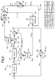
- Fig. 2 is a schematic diagram of an alternate embodiment of the present invention configured to accommodate noise.
- Eqn. [3], discussed in connection with the preferred embodiment of the present invention illustrated in Fig. 1, may be rewritten to account for white Gaussian noise in the form: where f(n) equals a time varying frequency of the received sinusoidal signal and f s equals sampling frequency.
- an apparatus 100 having a first delay circuit 102 and a second delay circuit 104.
- An input signal, x(n) is received by apparatus 100 at an input 106 to first delay circuit 102.
- First delay circuit 102 delays input signal x(n) one clock period and generates at an output 108 a once-delayed signal x(n-1);
- x(n-1) is substantially input signal x(n) delayed one clock period.
- Second delay circuit 104 receives once-delayed signal x(n-1) at an input 110 and delays once-delayed signal x(n-1) by one further clock period, generating at a twice-delayed signal x(n-2) at an output 112.
- Once-delayed signal x(n-1) is also applied to a multiplier 114 at an input 116.
- a first weighted factor source 118 provides a first weighted factor, W1(n), to an input 120 of multiplier 114.
- Multiplier 114 generates at an output 122 a weighted once-delayed signal which is substantially the product of once-delayed signal x(n-1) and first weighted factor W1(n). This weighted once-delayed signal is applied to an input 124 of a summing node 126.
- Twice-delayed signal x(n-2) is applied to an input 128 of a multiplier 130.
- Multiplier 130 also receives at an input 132 a second weighted factor, W2(n), from a second weighted factor source 134.
- Summing node 126 produces at an output 136 an estimation of input signal x(n), x ⁇ (n), estimated input signal x ⁇ (n) is applied to an input 138 of a summing node 140. Also received by summing node 140 at an input 142 is input signal x(n).
- Summing node 140 produces at an output 144 an error signal ⁇ .
- First weighted factor source 118 and second weighted factor source 134 are responsive to error signal ⁇ to vary first weighted factor W1(n) and second weighted factor W2(n) appropriately to reduce error signal ⁇ . That is, W1(n) and W2(n) are appropriately varied to reduce the difference between input signal x(n) and estimated input signal x ⁇ (n). As may be seen from inspection of Fig.
- x ⁇ (n) W1(n-1)x(n-1)+W2(n-1)x(n-2) [9]
- W2(n) W2(n-1)+ ⁇ (n)x(n-2) [11]
- Threshold circuit 166 is preferably designed to substantially implement the approximations represented by Eqn. [37] above, so that the signal, "A”, provided by threshold circuit 166 at its output 168 is variable, as indicated in the table associated with Fig. 2, according to the value of signal W1(n) received at input 164.
- the output signal provided by threshold circuit 166 is applied to an input 170 of multiplier 160 so that multiplier 160 provides at its output 172 a signal "B".
- Signal "B” varies as indicated in the table associated with Fig. 2, depending upon the value of W1(n) received at input 164 of threshold circuit 166.
- Signal "B” is applied to an input 174 of a summing node 176; the signal W1(n) is provided to a second input 178 of summing node 176 from first weighted factor source 118, and summing node 176 provides at its output 180 the value W1*.
- signal W1* is calculated by frequency identification circuit 150 in accordance with Eqn. [37] above.
- the value provided at output 180 of summing node 176 uniquely identifies the frequency of the sinusoidal signal, x s (n), received at input 106 of delay circuit 102 through a look-up table or similar arrangement in a logic circuit (not shown in Fig. 2).
- a second weighted factor, W2(n) is employed to estimate noise energy in the received signal x(n) and second weighted factor W2(n) is employed to apply a correction to first weighted factor W1(n) in order to accurately reflect an index uniquely identifying the sinusoidal wave form x s (n) contained within the received signal x n , which is received in the form of Eqn.
Landscapes
- Engineering & Computer Science (AREA)
- Computer Networks & Wireless Communication (AREA)
- Noise Elimination (AREA)
- Channel Selection Circuits, Automatic Tuning Circuits (AREA)
- Superheterodyne Receivers (AREA)
Applications Claiming Priority (2)
| Application Number | Priority Date | Filing Date | Title |
|---|---|---|---|
| US54408 | 1993-04-28 | ||
| US08/054,408 US5343414A (en) | 1991-11-22 | 1993-04-28 | Apparatus for adaptively tuning to a received periodic signal |
Publications (2)
| Publication Number | Publication Date |
|---|---|
| EP0622963A2 true EP0622963A2 (de) | 1994-11-02 |
| EP0622963A3 EP0622963A3 (de) | 1999-12-01 |
Family
ID=21990867
Family Applications (1)
| Application Number | Title | Priority Date | Filing Date |
|---|---|---|---|
| EP94302270A Withdrawn EP0622963A3 (de) | 1993-04-28 | 1994-03-29 | Einrichtung zur adaptiven Abstimmung auf ein empfangenes periodisches Signal |
Country Status (3)
| Country | Link |
|---|---|
| US (1) | US5343414A (de) |
| EP (1) | EP0622963A3 (de) |
| JP (1) | JPH0715286A (de) |
Families Citing this family (3)
| Publication number | Priority date | Publication date | Assignee | Title |
|---|---|---|---|---|
| US5867693A (en) * | 1997-07-03 | 1999-02-02 | Modern Video Technology, Inc. | Extended resolution phase measurement |
| US7356551B2 (en) * | 2003-03-14 | 2008-04-08 | Nxp B.V. | Method and apparatus of retaining maximum speed of flip-flop metastability based random number generators |
| US6906560B1 (en) * | 2004-01-20 | 2005-06-14 | Harris Corporation | Phase-continuous frequency synthesizer |
Family Cites Families (7)
| Publication number | Priority date | Publication date | Assignee | Title |
|---|---|---|---|---|
| US4326261A (en) * | 1980-06-23 | 1982-04-20 | Peoples John T | Single tone detector |
| US4438504A (en) * | 1981-06-15 | 1984-03-20 | Bell Telephone Laboratories, Incorporated | Adaptive techniques for automatic frequency determination and measurement |
| US4433422A (en) * | 1982-03-29 | 1984-02-21 | Sperry Corporation | Frequency measuring system for alternating frequency signals |
| US4791390A (en) * | 1982-07-01 | 1988-12-13 | Sperry Corporation | MSE variable step adaptive filter |
| US4715000A (en) * | 1985-08-06 | 1987-12-22 | General Electric Company | Digital phase-locked loop and frequency measuring device |
| US4839842A (en) * | 1987-07-24 | 1989-06-13 | Advanced Micro Devices | Digital tone detection and generation |
| US5189381A (en) * | 1991-10-31 | 1993-02-23 | Advanced Micro Devices, Inc. | Apparatus for generating a sinusoidal output signal |
-
1993
- 1993-04-28 US US08/054,408 patent/US5343414A/en not_active Expired - Lifetime
-
1994
- 1994-03-29 EP EP94302270A patent/EP0622963A3/de not_active Withdrawn
- 1994-04-26 JP JP6088466A patent/JPH0715286A/ja not_active Withdrawn
Also Published As
| Publication number | Publication date |
|---|---|
| JPH0715286A (ja) | 1995-01-17 |
| EP0622963A3 (de) | 1999-12-01 |
| US5343414A (en) | 1994-08-30 |
Similar Documents
| Publication | Publication Date | Title |
|---|---|---|
| Shnidman | Radar detection probabilities and their calculation | |
| US4470048A (en) | Range profile target classifier | |
| Wu et al. | Prediction of geomagnetic storms from solar wind data using Elman recurrent neural networks | |
| US4216463A (en) | Programmable digital tone detector | |
| US5566134A (en) | Digital computer algorithm for processing sonar signals | |
| US4075703A (en) | Recursive filter mean-level detector | |
| EP0584912A1 (de) | Empfänger mit Verwendung eines angepassten Filters und eines Mittelwertfilters | |
| US5357256A (en) | Radar receiver with adaptive clutter threshold reference | |
| US4633426A (en) | Method and apparatus for detecting a binary convoluted coded signal | |
| EP0144245A2 (de) | Sender- und Empfängersystem | |
| US4403298A (en) | Adaptive techniques for automatic frequency determination and measurement | |
| Carvalho et al. | A nonlinear equation with piecewise continuous argument | |
| US4627103A (en) | S/N ratio determining method and apparatus for a receiver | |
| US3833797A (en) | Statistical noise processor | |
| EP0622963A2 (de) | Einrichtung zur adaptiven Abstimmung auf ein empfangenes periodisches Signal | |
| US4634966A (en) | Binary processing of sound spectrum | |
| Maskell et al. | The estimation of subsample time delay of arrival in the discrete-time measurement of phase delay | |
| EP0543490B1 (de) | Einrichtung zur adaptiven Abstimmung auf ein empfangenes periodisches Signal | |
| KR19990057712A (ko) | 디지털 신호 처리장치 및 그 방법 | |
| Händel et al. | Performance analysis of a correlation based single tone frequency estimator | |
| DjuriC et al. | Bayesian spectrum estimation of harmonic signals | |
| US5377131A (en) | Digital amplitude estimator | |
| US5179529A (en) | High speed fourier transform engine | |
| WO1991010913A1 (en) | Coherent frequency burst detector apparatus and method | |
| JPS6340367B2 (de) |
Legal Events
| Date | Code | Title | Description |
|---|---|---|---|
| PUAI | Public reference made under article 153(3) epc to a published international application that has entered the european phase |
Free format text: ORIGINAL CODE: 0009012 |
|
| AK | Designated contracting states |
Kind code of ref document: A2 Designated state(s): BE DE DK ES FR GB GR IE IT LU NL PT SE |
|
| PUAL | Search report despatched |
Free format text: ORIGINAL CODE: 0009013 |
|
| AK | Designated contracting states |
Kind code of ref document: A3 Designated state(s): BE DE DK ES FR GB GR IE IT LU NL PT SE |
|
| RIC1 | Information provided on ipc code assigned before grant |
Free format text: 6H 04Q 1/457 A, 6H 04Q 1/30 B, 6H 04Q 1/46 B |
|
| 17P | Request for examination filed |
Effective date: 20000403 |
|
| 17Q | First examination report despatched |
Effective date: 20010109 |
|
| STAA | Information on the status of an ep patent application or granted ep patent |
Free format text: STATUS: THE APPLICATION IS DEEMED TO BE WITHDRAWN |
|
| 18D | Application deemed to be withdrawn |
Effective date: 20010522 |