EP0623432B1 - Vorrichtung zum Transport sowie zum Lochstanzen eines bandförmigen Materials - Google Patents
Vorrichtung zum Transport sowie zum Lochstanzen eines bandförmigen Materials Download PDFInfo
- Publication number
- EP0623432B1 EP0623432B1 EP94420095A EP94420095A EP0623432B1 EP 0623432 B1 EP0623432 B1 EP 0623432B1 EP 94420095 A EP94420095 A EP 94420095A EP 94420095 A EP94420095 A EP 94420095A EP 0623432 B1 EP0623432 B1 EP 0623432B1
- Authority
- EP
- European Patent Office
- Prior art keywords
- strip
- web
- vacuum
- drum
- track plate
- Prior art date
- Legal status (The legal status is an assumption and is not a legal conclusion. Google has not performed a legal analysis and makes no representation as to the accuracy of the status listed.)
- Expired - Lifetime
Links
Images






Classifications
-
- B—PERFORMING OPERATIONS; TRANSPORTING
- B26—HAND CUTTING TOOLS; CUTTING; SEVERING
- B26F—PERFORATING; PUNCHING; CUTTING-OUT; STAMPING-OUT; SEVERING BY MEANS OTHER THAN CUTTING
- B26F1/00—Perforating; Punching; Cutting-out; Stamping-out; Apparatus therefor
- B26F1/02—Perforating by punching, e.g. with relatively-reciprocating punch and bed
- B26F1/04—Perforating by punching, e.g. with relatively-reciprocating punch and bed with selectively-operable punches
-
- B—PERFORMING OPERATIONS; TRANSPORTING
- B26—HAND CUTTING TOOLS; CUTTING; SEVERING
- B26D—CUTTING; DETAILS COMMON TO MACHINES FOR PERFORATING, PUNCHING, CUTTING-OUT, STAMPING-OUT OR SEVERING
- B26D5/00—Arrangements for operating and controlling machines or devices for cutting, cutting-out, stamping-out, punching, perforating, or severing by means other than cutting
- B26D5/20—Arrangements for operating and controlling machines or devices for cutting, cutting-out, stamping-out, punching, perforating, or severing by means other than cutting with interrelated action between the cutting member and work feed
- B26D5/26—Arrangements for operating and controlling machines or devices for cutting, cutting-out, stamping-out, punching, perforating, or severing by means other than cutting with interrelated action between the cutting member and work feed wherein control means on the work feed means renders the cutting member operative
-
- B—PERFORMING OPERATIONS; TRANSPORTING
- B26—HAND CUTTING TOOLS; CUTTING; SEVERING
- B26F—PERFORATING; PUNCHING; CUTTING-OUT; STAMPING-OUT; SEVERING BY MEANS OTHER THAN CUTTING
- B26F1/00—Perforating; Punching; Cutting-out; Stamping-out; Apparatus therefor
- B26F1/0007—Perforation of photographic films
-
- B—PERFORMING OPERATIONS; TRANSPORTING
- B65—CONVEYING; PACKING; STORING; HANDLING THIN OR FILAMENTARY MATERIAL
- B65H—HANDLING THIN OR FILAMENTARY MATERIAL, e.g. SHEETS, WEBS, CABLES
- B65H20/00—Advancing webs
- B65H20/12—Advancing webs by suction roller
-
- B—PERFORMING OPERATIONS; TRANSPORTING
- B65—CONVEYING; PACKING; STORING; HANDLING THIN OR FILAMENTARY MATERIAL
- B65H—HANDLING THIN OR FILAMENTARY MATERIAL, e.g. SHEETS, WEBS, CABLES
- B65H20/00—Advancing webs
- B65H20/24—Advancing webs by looping or like devices
-
- B—PERFORMING OPERATIONS; TRANSPORTING
- B65—CONVEYING; PACKING; STORING; HANDLING THIN OR FILAMENTARY MATERIAL
- B65H—HANDLING THIN OR FILAMENTARY MATERIAL, e.g. SHEETS, WEBS, CABLES
- B65H23/00—Registering, tensioning, smoothing or guiding webs
- B65H23/04—Registering, tensioning, smoothing or guiding webs longitudinally
- B65H23/24—Registering, tensioning, smoothing or guiding webs longitudinally by fluid action, e.g. to retard the running web
-
- B—PERFORMING OPERATIONS; TRANSPORTING
- B65—CONVEYING; PACKING; STORING; HANDLING THIN OR FILAMENTARY MATERIAL
- B65H—HANDLING THIN OR FILAMENTARY MATERIAL, e.g. SHEETS, WEBS, CABLES
- B65H2301/00—Handling processes for sheets or webs
- B65H2301/40—Type of handling process
- B65H2301/44—Moving, forwarding, guiding material
- B65H2301/449—Features of movement or transforming movement of handled material
- B65H2301/4491—Features of movement or transforming movement of handled material transforming movement from continuous to intermittent or vice versa
-
- B—PERFORMING OPERATIONS; TRANSPORTING
- B65—CONVEYING; PACKING; STORING; HANDLING THIN OR FILAMENTARY MATERIAL
- B65H—HANDLING THIN OR FILAMENTARY MATERIAL, e.g. SHEETS, WEBS, CABLES
- B65H2406/00—Means using fluid
- B65H2406/10—Means using fluid made only for exhausting gaseous medium
- B65H2406/11—Means using fluid made only for exhausting gaseous medium producing fluidised bed
- B65H2406/112—Means using fluid made only for exhausting gaseous medium producing fluidised bed for handling material along preferably rectilinear path, e.g. nozzle bed for web
-
- B—PERFORMING OPERATIONS; TRANSPORTING
- B65—CONVEYING; PACKING; STORING; HANDLING THIN OR FILAMENTARY MATERIAL
- B65H—HANDLING THIN OR FILAMENTARY MATERIAL, e.g. SHEETS, WEBS, CABLES
- B65H2408/00—Specific machines
- B65H2408/20—Specific machines for handling web(s)
- B65H2408/21—Accumulators
- B65H2408/215—Accumulators supported by vacuum or blown air
-
- Y—GENERAL TAGGING OF NEW TECHNOLOGICAL DEVELOPMENTS; GENERAL TAGGING OF CROSS-SECTIONAL TECHNOLOGIES SPANNING OVER SEVERAL SECTIONS OF THE IPC; TECHNICAL SUBJECTS COVERED BY FORMER USPC CROSS-REFERENCE ART COLLECTIONS [XRACs] AND DIGESTS
- Y10—TECHNICAL SUBJECTS COVERED BY FORMER USPC
- Y10T—TECHNICAL SUBJECTS COVERED BY FORMER US CLASSIFICATION
- Y10T83/00—Cutting
- Y10T83/202—With product handling means
- Y10T83/2066—By fluid current
- Y10T83/207—By suction means
-
- Y—GENERAL TAGGING OF NEW TECHNOLOGICAL DEVELOPMENTS; GENERAL TAGGING OF CROSS-SECTIONAL TECHNOLOGIES SPANNING OVER SEVERAL SECTIONS OF THE IPC; TECHNICAL SUBJECTS COVERED BY FORMER USPC CROSS-REFERENCE ART COLLECTIONS [XRACs] AND DIGESTS
- Y10—TECHNICAL SUBJECTS COVERED BY FORMER USPC
- Y10T—TECHNICAL SUBJECTS COVERED BY FORMER US CLASSIFICATION
- Y10T83/00—Cutting
- Y10T83/444—Tool engages work during dwell of intermittent workfeed
- Y10T83/447—Plural tools successively actuated at same station
- Y10T83/4473—During one dwell period
-
- Y—GENERAL TAGGING OF NEW TECHNOLOGICAL DEVELOPMENTS; GENERAL TAGGING OF CROSS-SECTIONAL TECHNOLOGIES SPANNING OVER SEVERAL SECTIONS OF THE IPC; TECHNICAL SUBJECTS COVERED BY FORMER USPC CROSS-REFERENCE ART COLLECTIONS [XRACs] AND DIGESTS
- Y10—TECHNICAL SUBJECTS COVERED BY FORMER USPC
- Y10T—TECHNICAL SUBJECTS COVERED BY FORMER US CLASSIFICATION
- Y10T83/00—Cutting
- Y10T83/444—Tool engages work during dwell of intermittent workfeed
- Y10T83/463—Work-feed element contacts and moves with work
- Y10T83/4635—Comprises element entering aperture in, or engaging abutment surface on, work
-
- Y—GENERAL TAGGING OF NEW TECHNOLOGICAL DEVELOPMENTS; GENERAL TAGGING OF CROSS-SECTIONAL TECHNOLOGIES SPANNING OVER SEVERAL SECTIONS OF THE IPC; TECHNICAL SUBJECTS COVERED BY FORMER USPC CROSS-REFERENCE ART COLLECTIONS [XRACs] AND DIGESTS
- Y10—TECHNICAL SUBJECTS COVERED BY FORMER USPC
- Y10T—TECHNICAL SUBJECTS COVERED BY FORMER US CLASSIFICATION
- Y10T83/00—Cutting
- Y10T83/525—Operation controlled by detector means responsive to work
- Y10T83/533—With photo-electric work-sensing means
Definitions
- the invention is related to apparatus for transporting and perforating elongated strips of material. More particularly, the invention concerns such apparatus which is adapted for selectively producing a variety of patterns of perforations along the length of such strips by intermittently feeding a strip and selectively actuating a plurality of punch and die sets positioned along the path of movement of the strip, so as to produce such patterns on strips of different lengths.
- edge perforations which are used subsequently to drive or guide the strips through other apparatus.
- photographic film strips for personal cameras have long been provided with a continuous row of evenly, closely spaced perforations along both edges of the strips, the perforations being used during spooling of the strips, during winding of the film through the camera and during processing of the exposed film strips.
- numerous paper products are known in which continuous rows of evenly, closely spaced perforations are provided along the edges of the paper for use in feeding the paper through a processing apparatus such as a printer.
- Apparatus and methods for producing such continuous rows of evenly, closely spaced perforations are known, some requiring the use of sets of punches and dies which are actuated simultaneously as the strip is intermittently stopped for perforating; and some requiring the use of rotating drums with punches which perforate the continuously moving strip.
- the strip is then cut into shorter strips each having continuous patterns of perforations, such as strips for various numbers of exposures in the case of photographic film products.
- JP-A-2269598 published on November 2, 1990 describes an apparatus according to the preamble of claim 1. In order to prevent harmful scratch air, is transmitted through holes from upwards and downwards so that the film is supported in a non contacting state between a stripper member and a female member.
- US-A-4,928,562 describes a film perforator having a punch unit a feed roller on the upstream side of the punch unit and a sprocket moving device on the downstream of the punch unit.
- the tension in the web is obtained by driving the feed roller a little slower than the sprocket moving device and allowing slippage of the film with respect to the feed roller.
- US-A-5,106,017 describes a pneumatic film punch wherein a collection of individual punch pins are provided to place one or more openings on the edge of a sheet material.
- EP-A-605,802 which was published after the priority date of the instant application is mentioned in connection which Article 54(3) EPC. Said document describes a perforator wherein various sets of perforations could be realized by use of individual sets of punch pins.
- an elongated, flat track plate is provided on its upper surface with a plurality of gas flow apertures, each aperture being extended through and angled relative to the upper surface, whereby gas flowing through the apertures will support the strip above the upper surface.
- the apertures are angled in the direction of movement of the strip along the track plate and arranged in at least one longitudinally extending row with some of the apertures being angled toward one side edge of the plate and others being angled toward the other side edge of the plate.
- flows of air through the apertures will support the web above the surface.
- the web is intermittently moved along the track plate. When the web is stopped, means positioned along the track plate perforate the web, thereby over the course of two or more indexes permitting the application of a pattern of perforations to the web.
- the web is moved intermittently by a vacuum drum assembly positioned at the downstream end of the track plate, the rotor of the drum assembly preferably being formed as an integral part of the rotor of a servo motor.
- the vacuum stator of the vacuum drum assembly is provided with an initial atmospheric pressure plenum for permitting escape of air entrained between the web and the drum, a central low pressure plenum for applying vacuum to hold the web to the drum and a final at least atmospheric pressure plenum for easing the web's departure from the drum.
- Tension in the web is preferably controlled by an inlet vacuum box and an outlet vacuum box positioned, respectively, upstream of the track plate and downstream of the vacuum drum assembly.
- the angular position of the vacuum drum assembly and preferably also the positions of the web in the vacuum boxes are monitored as control parameters for the indexing cycle.
- the apparatus of the invention permits accurate, high speed indexing of a web of material through a perforator apparatus and the application of patterns of widely spaced perforations and leader/trailer portions to such a web during brief dwell times between indexes of the web.
- Figure 1 shows a schematic elevation view of the apparatus according to the invention.
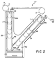
- Figure 2 shows an enlarged schematic elevation view of the infeed and outfeed vacuum box assembly.
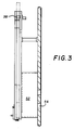
- Figure 3 shows a side elevation view of the apparatus of Figure 2.
- Figure 4 shows a plan view of a fragment of an elongated web of material which has been provided with a pattern of widely spaced perforations and leader/trailer sections using the apparatus and method of the invention.
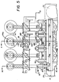
- Figure 5 shows a front elevation view of the perforator apparatus.
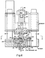
- Figure 6 shows the lower half of a view taken along line 6-6 of Figures 5 and 10.
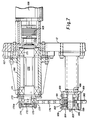
- Figure 7 shows the upper half of a view taken along line 6-6 of Figures 5 and 10.
- Figure 8 shows a plan view of the bottom die plate.
- Figure 9 shows a plan view of an individual punching die.
- Figure 10 shows a view, partially broken away, taken along line 8-8 of Figure 6.
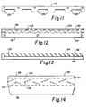
- Figure 11 shows a plan view of an edge guide used in the perforator apparatus.
- Figure 12 shows a plan view of the track plate used in the perforator apparatus.
- Figure 13 shows an elevation view in section of the track plate of Figure 12.
- Figure 14 shows an enlarged fragmentary view of the track plate of Figures 12 and 13.
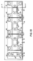
- Figure 15 shows a plan view of the perforator apparatus taken along line 15-15 of Figure 5.
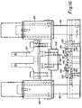
- Figure 16 shows the lower half of a view taken along line 16-16 of Figure 5, similar to the view of Figure 6.
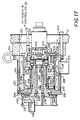
- Figure 17 shows a sectional view of the high performance vacuum drum, some parts being rotated into the plane of view for ease of illustration, taken along line 17-17 of Figure 23.
- Figure 18 shows a sectional view of the rotor for the vacuum drum, taken along line 18-18 of Figure 19.
- Figure 19 shows an end view of the rotor, as seen from the left of Figure 18.
- Figure 20 shows an enlarged fragmentary sectional view of the rim of the vacuum drum, indicating the grooves and passages for applying and releasing vacuum.
- Figure 21 shows an enlarged fragmentary plan view of the rim of the vacuum drum, also indicating the grooves and passages for applying and releasing vacuum.
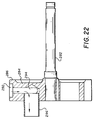
- Figure 22 shows an elevation view, partially in section, of the vacuum stator for the vacuum drum, taken along line 22-22 of Figure 23.
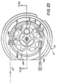
- Figure 23 shows an end view of the apparatus, as seen from the left side of Figure 17.
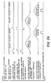
- Figure 24 shows a timing or operating cycle chart for a cycle of operation of the apparatus of the invention.
- Figure 1 illustrates schematically an apparatus according to the invention which can selectively provide a variety of patterns of widely spaced perforations and leader/trailer sections on strips of photographic film or other materials, with high accuracy and at average web speeds in excess of 500 feet (152.4 m) per minute.
- a frame 10 supports a rigid metal face plate 12 on which the major components of the apparatus are mounted.
- the web 14 to be perforated is provided from an unwind stock roll 16 which in operation is driven to provide a substantially constant web speed by a servomotor mounted on the back side of face plate 12 and not illustrated.
- Web 14 passes from roll 16 over a first idler roller 18, under a second idler roller 20 and over a third idler roller 22, from which it passes into an infeed vacuum box 24 which may be of conventional design.
- idler roller 22 may be replaced with an infeed vacuum drum 51.
- a loop 26 of web 14 rises and falls within vacuum box 24 in the familiar manner, so that an essentially constant tension is maintained on the web leaving vacuum box 24.
- a conventional air bar 28 which may be of the type shown in commonly assigned U.S. Patent 4,889,269, is mounted on face plate 12 to guide web 14 from vacuum box 24 through an approximately ninety degree turn and onto the track plate of the selectable perforator apparatus 30.
- the web is wrapped approximately 135 degrees around a high performance, intermittently operated vacuum drum 32, from which the web passes into an outfeed vacuum box 34, which may be of conventional design.
- a loop 36 of web rises and falls within vacuum box 34 in the familiar manner, so that an essentially constant tension is maintained on the web entering vacuum box 34.
- Web 14 passes from vacuum box 34 over a first idler roller 38, under a second idler roller 40 and over third idler roller 42, from which it passes to a rewind stock roll 44 which in operation also is driven to provide a substantially constant web speed by a servomotor mounted on the back side of face plate 12 and not illustrated.
- vacuum box 34 preferably would have sufficient length to accommodate a loop 36 having a length approximately that of the longest strip to be cut and spooled.
- the apparatus shown in Figures 1 and 2 is capable of high speed perforating of web 14. While unwind stock roll 16 and rewind stock roll 44 are rotated to maintain an essentially constant web speed, web 14 feeds into infeed vacuum box 24 and out of vacuum box 34 until infeed loop 26 reaches a maximum length as sensed by a photocell detector 46; and at the same time, outfeed loop 36 reaches a minimum length as sensed by a photocell detector 48.
- photocell detectors 46, 48 provide signals to a conventional programmable motion controller 50 which causes vacuum drum 32 to rotate and simultaneously advance a predetermined length of web 14 (a) away from perforator apparatus 30 and into outfeed vacuum box 34 and (b) out of infeed vacuum box 24 and into perforator apparatus 30. Vacuum drum 32 then dwells very briefly while perforator apparatus 30 is actuated by controller 50 to produce the perforations desired on the stationary portion of web 14.
- perforator apparatus 30 comprises a plurality of independently actuatable punch and die sets which can selectively produce a desired pattern of perforations during each dwell period.
- controller 50 again actuates vacuum drum 32 and the process repeats.
- both the pattern of perforations made during each dwell period and the length of web 14 advanced between dwell periods can be selected to produce an overall desired pattern along the length of web 14.
- infeed vacuum box 24 may be provided with a low limit photocell detector 46a and a high limit photocell detector 46b
- outfeed vacuum box 34 may be provided with a low limit photocell detector 48a and a high limit photocell detector 48b. For example, operation may be stopped if infeed loop 26 moves above detector 46a.
- the vacuum box system shown in Figures 1 to 3 is useful for imparting a desired level of tension to a stationary span of web 14 positioned on a track plate within perforator apparatus 30, while minimizing tension transients in web 14 during periods of intermittent acceleration and deceleration.
- the vacuum box system also acts as a buffer between the region of continuous motion of web 14 from unwind stock roll 16 and the region of continuous motion of web 14 to rewind stock roll 44.
- Vacuum drum 32 also helps to isolate perforator apparatus 30 from downstream tension transients. Or, if rewind stock roll 44 is replaced by apparatus for cutting web 14 into shorter strips and winding them onto spools, the vacuum box system and vacuum drum 32 buffer perforator apparatus 30 from the intermittent operation of such a cutting and winding apparatus.
- Each of vacuum boxes 24 and 34 in the conventional manner comprises an elongated box structure open at its upper end, the box having a length corresponding to the maximum desired length of loop to be stored in the box and a width somewhat wider than the width of the web to be tensioned.
- the web enters the box over a vacuum drum 51 or 32, or over an idler roller 22 or an air bar, and exits over another air bar 28 or roller 38.
- the air pressure above the loops 26, 36 typically is atmospheric, while below loops 26, 36 a subatmospheric pressure is applied by connecting both vacuum boxes to a vacuum line 54 connected to a vacuum source, not illustrated.
- the difference in pressure across the loops 26, 36 acts on the projected surface area of web 14 parallel to the closed end of boxes 24, 34 and induces a tension in the web.
- vacuum boxes 24, 34 are low inertia tension control systems which eliminate the need for roller accumulators and tensioners which have high inertia and can cause scratches on web 14 during high accelerations.
- vacuum box 34 is set at an angle with its lower end closer to vacuum box 24; so that, a desired wrap angle is achieved on vacuum drum 32; and, when the vacuum boxes are connected to a common plenum as in the preferred embodiment of the invention, the air exchange distance between loops 26, 36 is substantially reduced.
- the pressure below the loops is substantially the same as that applied to vacuum line 54.
- a first factor is the inertial tension disturbance due to acceleration of the mass of the web. This typically is a rather small component of a tension transient.
- a second factor is the tension disturbance due to acceleration of the mass of the volume of air which moves in response to movement of the loop. This volume includes air above and below the loop, both in the vacuum box.
- a third factor is the tension disturbance due to the dynamic change in the pressure below the loop that occurs when the volume of air beneath the loop changes and before sufficient flow has occurred through the impedance of the interconnecting piping to allow the pressures above and below the loop to reach new steady values.
- vacuum boxes 24, 34 preferably communicate pneumatically to a common vacuum plenum 52; so that, loops 26, 36 are exposed on their low pressure sides to essentially the same subatmospheric pressure. Also, common vacuum plenum 52 ensures that an essentially even exchange of air occurs between the two vacuum boxes during an index of web 14. With web 14 stopped while perforator apparatus 30 is actuated, loop 26 typically will be longer than loop 36.
- the length of each box preferably is one half an index length plus an additional length to account for minor drift in loop heights, due to errors in control, for example.
- the overall box length then approaches the full index length.
- web 14 is fed into vacuum box 24 and pulled from vacuum box 34, so as to restore the conditions that existed before the preceding index.
- feeding and pulling of web 14 can happen in a continuous manner while the web within perforator apparatus 30 moves intermittently to allow perforation of a stationary portion of web 14.
- a continuously running infeed vacuum drum 51 is used rather than idler roller 22 since drum 51 will prevent the web from being drawn uncontrollably into vacuum box 24 during an upstream loss of tension.
- Figure 4 illustrates fragmentarily a strip of web material, such as photographic film, having a pattern of widely spaced perforations and leader/trailer sections along its length.
- the apparatus and method of the invention are particularly adapted to producing such widely spaced perforations and leader/trailer sections, they may also be used to produce conventional, closely spaced perforations on either or both sides of a strip.
- the long strip is to be perforated and eventually cut into shorter strips each having a leader portion 60 with a geometry, not illustrated, for engaging the core of a spool in a camera and a trailer portion 62 for engaging the core of a spool in a film magazine.
- the direction of web movement is from left to right toward stock roll 44.
- each trailer portion 62 would be engaged with the core of a spool in a film magazine. But, if stock roll 44 were replaced by an apparatus for cutting web 14 into strips and winding the strips onto spools, the positions of leader portion 60 and trailer portion 62 would have to be reversed leaving perforator apparatus 30. Between leader portion 60 and trailer portion 62, each strip may be provided, for example, with widely spaced perforations 64 along one or both edges, each perforation being positioned, for example, to correspond to the location of a frame to be exposed on the film or for other purposes.
- Trailer portion 62 may also be provided, for example, with two or more feature perforations 66 at a different transverse location from perforations 64, feature perforations 66 being positioned to be sensed by or to coact in a desired manner with the camera.
- the pattern of perforations is non-continuous in the sense that there are lengthy leader and trailer portions of each film strip which have no perforations, portions which have widely spaced perforations to locate frames and portions which have feature perforations.
- the apparatus and method of the invention are particularly suited for producing such patterns of perforations; and those skilled in the art will appreciate that perforator apparatus 30, now to be described in detail, can readily be configured to produce a myriad of such patterns, as well as to produce continuous patterns of closely spaced perforations.
- Figures 5 to 16 illustrate certain details of perforator apparatus 30.
- a bracket is provided comprising a plate 68 mounted to face plate 12, plate 68 being secured along its upper edge to an elongated horizontal support plate 70.
- An elongated die support plate 72 is attached to the upper surface of support plate 70 and has attached to its upper surface a fixed bottom shoe 74 for the dies to make feature perforations 66, plus a plurality of fixed, essentially identical bottom shoes 76, 78, 80 to make edge perforations 64.
- Figures 6 and 8 illustrate bottom shoes 76, 78, 80.
- Figure 16 illustrates bottom shoe 74.
- four guide rods 82 extend upwardly from each of bottom shoes 76, 78, 80 and two guide rods 82 are provided on bottom shoe 74.
- a movable upper shoe 84 is slidably mounted on the pair of guide rods 82 supported by bottom shoe 74, while essentially identical movable upper shoes 86, 88, 90 are slidably mounted on the two pairs of guide rods supported by each of bottom shoes 76, 78, 80.
- the upper surfaces of fixed bottom shoes 76, 78, 80 each are provided with respective aligned, elongated recesses 81 each of which receives an individual, elongated air track plate 92 having a flat upper surface 94 and side edges 96, 98, as illustrated in Figures 6, 10 and 12 to 14.
- Track plate 92 is of the general type disclosed in WO-A-9 205 467.
- track plate 92 On its underside, track plate 92 is provided with a centrally located, axially extended recess 100 which serves as an air plenum and is essentially centered on web 14.
- Pneumatically connecting recess 100 to upper surface 94 are a plurality of apertures 102 located essentially on the centerline of web 14.
- Apertures 102 extend through track plate 92 at an angle of preferably about 45 degrees to upper surface 94. Apertures 102 are angled alternately toward side edges 96, 98 at angles of preferably about 20 degrees.
- the diameter of apertures 102 is preferably about 0.022 inch (0.056 cm). Alternate apertures preferably are spaced on a pitch of about 0.648 inch (1.646 cm) along track plate 92. With apertures 102 configured and sized in this manner, a flow of air from recess 100 through apertures 102 will support a strip of photographic film centered on the row of apertures and also will urge the strip axially along the track plate in the desired direction of movement.
- Fasteners such as a plurality of bolts 104 may be used to secure track plate 92 to bottom shoes 76 - 80.
- perforation dies may be placed along both side edges of track plate 92, as in the feature punch and die arrangement of Figure 16, in the preferred embodiment for bottom shoes 76, 78, 80 a plurality of short die segments 106 are arranged along and abutting one side edge, preferably one die segment for each punch to simplify maintenance. See Figures 6, 9 and 10 Means such as locator pins 108 and other fasteners not illustrated may be used to secure die segments 106 to the bottom shoe.
- the bore 110 of each die segment communicates with a downwardly extended passage 112 for removal of chips created during punching.
- the uppermost surface 114 of each die segment is positioned coplanar with surface 94 of track plate 92 to provide a smooth surface over which web 14 moves.
- surface 114 includes a transversely extended, centrally positioned portion 116 which provides sufficient material surrounding bore 110 to permit proper dressing and peening of the die at assembly.
- each bottom shoe is stepped downwardly and then extends transversely away from track plate 92 to define a support surface 118 for a continuous stripper plate and edge guide assembly 120 which is bolted from beneath to the bottom shoe.
- assembly 120 extends along the entire length of track plate 92 and has a transverse flange 122 which extends above surface 114 of each die segment 106.
- Flange 122 includes a plurality of through holes 124 which are aligned with bores 110 in the die segments.
- edge guide 126 Attached to the underside of flange 122 is an edge guide 126, shown in Figure 11, having a plurality of lateral bosses 128 which extend toward die segments 106 on either side of central portions 116, as best seen in Figure 10.
- a set of spring plungers 130 biases edge guide 126 against a downwardly extending lip 132 on flange 122, leaving slight clearance between bosses 128 and die segments 106.
- a precision ground spacer 134 is attached to the downwardly extending body of assembly 120 to precisely position holes 124 above bores 110 in die segments 106 and to position edge guide 126.
- a set of spring plungers 136 biases assembly 120 and spacer 134 against a wall 138 in the bottom shoe.
- a second edge guide 140 is attached to the underside of a keeper flange 142 having a downwardly extending lip 144 against which edge guide 140 bears.
- Keeper flange 142 extends above surface 114 of each die segment 106 and is bolted from beneath to the bottom shoe. Flanges 122 and 142 thus prevent the edges of the film from lifting too far above surface 94 of track plate 92.
- bottom shoes 76, 78, 80 include on either side of the bottom surface of recess 81 a plurality of transversely opposed, axially extended slots or passageways 146, 148 which open through the bottom of the bottom shoe.
- Slots 146 open beneath bores 110 in each die segment 106 and between bosses 128 on edge guides 126.
- slots 148 open beneath edge guides 140 and between their bosses 141.
- slots 146 provide a pathway for removal of debris generated during operation of perforator apparatus 30.
- slots 146, 148 provide pathways for flow of air from apertures 102 in track plate 92 beneath web 14 and outwardly past the edges of the web, substantially without forcing the air to flow upward and then back over the web beneath flanges 122, 142. Due to the easy flow of air through slots 146, 148, web 14 is supported during movement slightly above track plate 92, due to the Bernoulli effect. Also, dirt that is scraped free from the edges of web 14 will fall through slots 146 and 148, thus minimizing dirt buildup in perforator apparatus 30.
- each of movable upper shoes 84 to 90 supports two or more punch members for providing one or the other of perforations 64, 66.
- each punch comprises a stick-like body portion 152, preferably having a generally rectangular cross section with the cutting end of the punch extending from the underside of a punch block 154 attached to the underside of the upper die shoe.
- a plurality of set screws 156 secures each punch in its punch block above bore 110 in the corresponding die segment 106.
- punch members 152 are provided at each of punches 76, 86; 78, 88; and 80, 90, while two punch elements are provided at feature punch 74, 84.
- punch members 152 are provided at each of punches 76, 86; 78, 88; and 80, 90, while two punch elements are provided at feature punch 74, 84.
- other numbers of punch elements could be provided without departing from the scope of our invention.
- a cylindrical housing 166 is mounted to face plate 12 by means of a support plate 167.
- a motor 168 is mounted to the rear of housing 166 and is connected by a coupling 169 to a driven shaft 170 supported for rotation within housing 166 by a pair of bearings 171.
- an eccentric stub shaft 172 is mounted, the degree of eccentricity of shaft 172 determining the range of movement of the associated punch elements 152.
- a knurled hand wheel 173 also is mounted to the front end of shaft 170 to permit manual movement of the punches as necessary during set up and maintenance, for example.
- Stub shaft 172 supports a bearing 174 whose outer race mates with a bore 175 provided in a surrounding concentric collar 175 a.
- Collar 175a is rigidly attached to the crank end 177 of a downwardly extended link 178.
- the drive end 181 of link 178 is provided with a clevis or similar fitting 182 which supports a shaft 183 of a spherical bearing 184.
- Supported by bearing 184 is a link 185 whose lower end is attached to a further spherical bearing 186 pivotably mounted by a shaft 186a to a bracket 187 attached to the upper surface of each upper shoe 84 - 90.
- shaft 183 is provided, preferably at both ends, with a modified Watt straight line mechanism.
- a diametrically extended arm 188 is mounted at each end of shaft 183, with the ends of the arm being equally spaced from the axis of the shaft.
- Each end of arm 188 is connected to an essentially horizontally extended flexure 189 whose other end is fixed to a mount 190 attached to face plate 12.
- link 185 moves up and down on an essentially vertical path; thereby minimizing transverse movement or loading on punches 152 and ensuring more accurate formation of perforations 64, 66 in web 14.
- Figure 16 shows an elevation view of the feature punch and die set for producing perforations 66.
- track plate 92' is functionally the same as track plate 92, though shorter.
- feature perforations 66 are provided on both sides of the center line of web 14, as seen in Figure 4, die segments 106', functionally the same as segments 106, are provided on both sides of track plate 92' along with their respective stripper plate and edge guide assemblies 120', 126', 134'.
- punches 152' can be driven downward in the manner previously discussed to pass through the bores in the stripper plates, the web and the bores in the die segments to form feature perforations 66.
- Vacuum drum 32 is particularly suited for indexing web 14 through perforator apparatus 30 to permit the application of various non-continuous formats of perforations at high throughput rates.
- the most demanding operation of perforator apparatus 30 requires accurate positioning of web 14 between indexes while operating at average index web speeds in excess of 500 feet (152.4 m) per minute, with peak web speeds as high as 1500 feet (457.2 m) per minute.
- a drum 32 approximately 5.7107 inches (14.505 cm) in diameter must index one revolution in about 120 milliseconds, which can produce accelerations more than twenty times that of gravity. A single revolution is advantageous since it eliminates the effects of drum runout between indexes.
- the torsional resonance of the drum must be high enough to enable the drum to be controlled quickly and precisely to each new position; so that, perforation of web 14 can be done during a short dwell time of, say, 60 milliseconds.
- a conventional ported vacuum drum may or may not be used.
- an annular spacer ring 210 is used to position a cylindrical motor housing 212 at a distance from face plate 12, a plurality of bolts 214 being passed from the back side of face plate 12, through spacer ring 210 and threaded into a base flange on motor housing 212.
- An opening 216 through face plate 12 allows access to the back side of the vacuum drum assembly.
- Motor housing 212 comprises a plurality of axially extending passages 218 for cooling air, the passages being connected by radial ports 220 to an inlet plenum for cooling air which is defined between a cylindrical magnetic shield 222 and the housing.
- a radially extending inlet port 224 is attached to shield 222 to provide a convenient connection to a source of cooling air, not illustrated.
- vacuum drum rotor 228 comprises a hollow rotor shaft 234 with a central bore 236.
- shaft 234 is provided with a cylindrical front bearing support surface 238 bounded at its front end by a shoulder 240 and a cylindrical back bearing support surface 242 bounded at its front end by a shoulder 244.
- shaft 234 is provided with a cylindrical front pilot surface 246, which is bounded at its front end by a shoulder 248 and provided with a circumferential groove 250 for an O-ring.
- a cylindrical back pilot surface 252 In front of back bearing surface 242 is provided a cylindrical back pilot surface 252, in front of which is located a circumferential groove 254 for another O-ring.
- vacuum drum rotor 228 In front of shoulder 240, vacuum drum rotor 228 comprises a preferably integral, radially extending flange 256 having a plurality of circumferentially spaced, axially extended holes 258 for lowering the polar moment of inertia of the rotor.
- Vacuum drum rotor 228 may be made from materials lighter than steel such as aluminum, titanium or various composite materials, which further improve the performance of the apparatus by lowering the polar moment of inertia of the rotor and permitting somewhat higher accelerations.
- Figures 20 and 21 illustrate fragmentarily the pattern of grooves and vacuum passages at the cylindrical surface of shell 260 which enable vacuum drum 32 to grip web 14 during indexing.
- a pattern of this general sort is illustrated in commonly assigned U.S. Patent 3,630,424.
- a plurality of circumferentially extending grooves 264 are provided across the axial width of shell 260, the grooves being preferably about 0.007 inch (0.018 cm), deep and preferably about 0.015 inch (0.038 cm), wide.
- the axial spacing between grooves 264 preferably is about 0.100 inch (0.254 cm).
- Grooves 264 are interconnected by a plurality of axially extending cross-feed grooves 266, grooves 266 being preferably about 0.020 inch (0.051 cm), deep and preferably about 0.016 inch (0.041 cm), wide. Preferably, grooves 266 are spaced about 5 degrees apart for a shell 260 having the diameter previously mentioned.
- a plurality of radial holes 268 are provided, preferably about 0.041 inch (0.104 cm) in diameter, from the interior surface 270 of shell 260 to axially spaced intersections of grooves 264, 266, to permit application of reduced or elevated air pressure to the underside of web 14.
- bore 236 includes a cylindrical front pilot surface 272 bounded at its back end by a shoulder 274, and a cylindrical back pilot surface 276.
- a front bearing 278 and a rear bearing 280 are mounted on pilot surfaces 272, 276 to support the stationary shaft 282 of vacuum drum stator 230.
- a bearing spacer sleeve 283 surrounds shaft 282 and extends between bearings 278, 280.
- shaft 282 supports at its front end a stator manifold 284 having an exterior, right circular, cylindrical surface 286 which fits closely within interior surface 270 on shell 260, to ensure an even application of vacuum in a manner to be described.
- Exterior surface 286 is provided with a circumferentially extending recess 288 which extends over an arc of preferably about 52 degrees, to form an ambient air plenum which is vented to atmospheric pressure through a pair of radial bores 290.
- Adjacent recess 288 is a second circumferentially extending recess 292 which extends over an arc of preferably about 90 degrees, to form a low pressure or vacuum plenum which communicates through an arcuate, radially extending passage 294 with an axially extending vacuum port 296 for connection to a low pressure source such as a vacuum pump, not illustrated.
- Adjacent recess 292 is a third circumferentially extending recess 298 which extends over an arc of preferably about 32 degrees, to form an atmospheric or high pressure plenum with a port 300 for connection to atmosphere or a source of high pressure air.
- a rigid link 302 extends between manifold 284 and face plate 12 to fix vacuum drum stator 230 against rotation.
- the magnet assembly 304 of motor 232 is bonded to a rotor sleeve 306 with a suitable adhesive.
- the assembly is then slipped over pilot surfaces 246, 252. Since there is clearance between sleeve 306 and surfaces 246, 252, a pair of O-rings 308 are provided in grooves 250, 254 to ensure that the sleeve remains concentric with the pilot diameters during assembly and preloading.
- the O-rings also ensure that motor 232 will perform at maximum efficiency by keeping the concentricity of the parts within acceptable limits.
- a flat preload ring 310 is pressed against the back end of sleeve 306 by a stack of disk springs 312 which in turn are preloaded by the inner race of a back bearing 314 mounted on bearing surface 242.
- Disk springs 312 preload sleeve 306 against bearing 344 which, in turn, bears against shoulder 240. The friction from the preload transmits the necessary torque to vacuum drum rotor 228.
- Disk springs 312 also compensate for thermal expansion.
- Bearing 314 is pressed against springs 312 by a retainer cap 316 attached to the back end of shaft 234 by suitable fasteners such as a plurality of bolts 318. Retainer cap 316 thus rotates with shaft 234.
- a torsionally rigid encoder coupling 320 is attached between retainer cap 316 and an encoder 322 mounted on an encoder housing 324 which is mounted on the back end of motor housing 212 by suitable fasteners such as a plurality of bolts 326.
- a rigid, annular compression plate 328 In front of encoder housing 324, a rigid, annular compression plate 328 comprises a plurality of backwardly opening, circumferentially spaced pockets 330, only one of which is visible in Figure 17. Each pocket retains a compression spring 332 which is engaged by the front face of encoder housing 324. Springs 332 provide the frictional force necessary to prevent the motor armature from rotating and also compensate for thermal expansion. Compression plate 328 thus is forced into contact with the first of one or more cylindrical spacers 334, the front one of which bears against the back side of the armature of motor 232.
- the front side of the armature bears against a further cylindrical spacer 336 which contacts a front bearing pilot ring 338 mounted to the front end of motor housing 212 by suitable fasteners such as bolts 340.
- a pilot bore 342 within ring 338 mounts a front bearing 344 which is supported on front bearing surface 238 of vacuum drum rotor 228.
- web 14 moves from track plate 92 of perforator apparatus 30 and engages vacuum drum 32 in the manner shown in Figure 23.
- the total wrap of web 14 around vacuum drum shell 260 can be any angle, but preferably is about 135 degrees; so that, the web does not wrap completely around recesses 288, 298 of stator manifold 284.
- the minimum angle of wrap is limited by the smallest recess 292 which can be used to reliably control and index web 14; whereas, the maximum angle of wrap is limited by the need to avoid interference of the incoming and outgoing spans of web.
- a wide variety of web transport systems requiring accurate repeatability of indexes at high accelerations can be provided with a vacuum drum of the type shown in Figures 17 to 23.
- the index distance or number of revolutions of the drum during an index can be fractional or any number desired, simply by programming the operation of servo motor 232, which also permits changing the number of revolutions from index to index.
- web 14 is photographic film which is to be perforated with successive patterns of perforations each having a leader portion 60, a feature perforation 66, twenty single perforations 64 to identify twenty frames to be exposed and a trailer portion 62, in the general manner shown in Figure 4.
- leader portion 60 and trailer portion 62 combined are seven pitches long, one pitch being the space between perforations 64.
- web 14 is stopped within perforator apparatus 30, which has just completed a preceding pattern.
- a typical cycle of operation to provide the next non-continuous pattern of perforations would be governed by controller 50 in accordance with a program of the type illustrated by the timing chart of Figure 24.
- controller 50 may determine the necessary angular velocities of stock rolls 16 and 44 to maintain essentially constant web speed.
- conventional sensors may be provided to measure the diameter of the material wound onto the rolls at start up and during operation.
- idler rollers 18, 38 may be provided with encoders to monitor the length of material passing over a period of time, which can then be used with a measured angular displacement of stock rolls 16 and 44 to determine the diameters of the stock rolls.
- controller 50 can readily accelerate the system to operating speed.
- the infeed loop 26 would initially be placed at the level of a photocell detector 46a and the outfeed loop 36 would be placed at a photocell 48b. See Figure 2.
- a cycle of operation then would proceed in the following manner.
- Web 14 is supplied to vacuum box 24 and removed from vacuum box 34 at a substantially constant and equal rate.
- loop 26 covers sensor 46 and loop 36 uncovers sensor 48
- vacuum drum 32 indexes to advance web 14 from vacuum box 24 through perforating apparatus 30 to vacuum box 34.
- appropriately selected punch drive motors 168 are started on a coordinated motion trajectory that will cause the corresponding punches 152 to pass through and retract from web 14 after web 14 has settled to a stop at the end of the vacuum drum motion.
- the average rate of incoming and outgoing web must be matched well enough to prevent accumulation of error from causing the vacuum boxes to be filled beyond capacity or completely emptied. This may be done by monitoring the sequence and time interval between movement of loop 26 past sensor 46 during downward travel as web 14 enters the apparatus, and movement of loop 36 past sensor 48 during upward travel as web 14 leaves the apparatus. Given that the nominal web velocity is known and that the desired length of web 14 within the apparatus should cause both sensors 46 and 48 to respond simultaneously to passage of loops 26 and 36, the error in length of web present can be calculated by controller 50. This error can then be used to control adjustments in the incoming or outgoing web velocity in order to regain the desired nominal operating condition.
- web 14 is moved a distance of fifteen pitches. That is, eight pitches from the preceding cycle plus seven pitches for leader/trailer, which places the last perforation 64 seven pitches away from the right-most punch element 152 in punch 78, 88. Then punches 76, 86 and 78, 88 are actuated to form the first eight perforations 64 of the current cycle.
- web 14 is moved twelve more pitches to place the first perforation 64, produced by the left most punch element 152 in punch 76, 86, one pitch to the right of the right most punch element in punch 80, 90. All four punches are then actuated to produce the remaining twelve perforations 64, plus special feature perforations 66. This process then repeats for subsequent strips.
- punches 78, 88 and 80, 90 would be actuated to punch the final eight perforations of a twenty frame strip.
- vacuum drum 32 would index the web fifteen pitches (eight pitches plus seven pitches for the leader and trailer portions).
Landscapes
- Life Sciences & Earth Sciences (AREA)
- Forests & Forestry (AREA)
- Engineering & Computer Science (AREA)
- Mechanical Engineering (AREA)
- Perforating, Stamping-Out Or Severing By Means Other Than Cutting (AREA)
- Advancing Webs (AREA)
- Control Of Cutting Processes (AREA)
Claims (7)
- Vorrichtung zum Perforieren eines bandförmigen Materials (14) miteiner länglichen Spurplatte (92), die Seitenkanten (96, 98) und eine erste Oberfläche (94) aufweist;einer Vielzahl von Gasaustrittsöffnungen (102), die entlang der Spurplatte angeordnet sind, um das bandförmige Material oberhalb der ersten Oberfläche zu führen;einem Mittel zum Lenken von Druckluft durch die Öffnungen;einer Einrichtung (24, 32, 34) zum intermittierenden Bewegen des bandförmigen Materials in der Bewegungsrichtung entlang der Spur; undeiner Perforationseinrichtung (30) mit einer Vielzahl von entlang der Spur angeordneten Stempeln und Matrizen zum Perforieren des bandförmigen Materials, wenn der Streifen durch die Einrichtung zum intermittierenden Bewegen angehalten wird;
dadurch gekennzeichnet, daßa) sich jede der Gasaustrittsöffnungen (102) über die gesamte erste Oberfläche unter einem Winkel zu dieser erstreckt, so daß das Band durch den Bernoulli-Effekt geführt wird;b) die Einrichtung zum intermittierenden Bewegen des Bandes folgende Komponenten aufweist:eine in der Bewegungsrichtung des Bandes nach der Spurplatte angeordnete Unterdruckwalze (32);ein Mittel (232) zum intermittierenden Drehen der Walze, um das Band über die Spurplatte zu bewegen; undein Mittel (320) zum Messen der Walzendrehung, undc) die Vorrichtung ein Mittel (50) aufweist, das die Arbeitsweise der Stempel und Matrizen in Abhängigkeit von dem Mittel zum Messen individuell steuert. - Vorrichtung nach Anspruch 1, dadurch gekennzeichnet, daß die Perforationseinrichtung mindestens eine stationäre Matrize (74, 76, 78, 80) mit einer zweiten Oberfläche (114), die mit der ersten Oberfläche im wesentlichen koplanar verläuft, wobei die stationäre Matrize an einer der Seitenkanten angeordnet ist und eine Vielzahl von entlang der Spurplatte gegenüber dem Band beabstandet angeordneten Matrizenöffnungen, eine Vielzahl von mit den Matrizenöffnungen ausgerichteten Stempeln (84, 86, 88, 90) und eine Einrichtung (168, 170, 172, 178, 182, 184) aufweist, die eine oder eine ausgewählte Anzahl der Stempel durch das Band und in die Matrizenöffnungen bewegt und dadurch das Band perforiert.
- Vorrichtung nach Anspruch 1 oder 2, dadurch gekennzeichnet, daß die Einrichtung zum intermittierenden Bewegen folgende Komponenten aufweist:eine erste, vor der Spurplatte angeordnete Unterdruckkammer (24) zum Aufnehmen einer ersten Schleife (26) des Bandes und Halten der Bandspannung;ein Mittel (46b) zum Feststellen einer maximal erwünschten Größe der ersten Schleife in der ersten Unterdruckkammer und Abgeben eines Signals an das Mittel zum Steuern der Stanzarbeit;eine zweite, nach der Walze angeordnete Unterdruckkammer (34) zum Aufnehmen einer zweiten Schleife (36) des Bandes und Halten der Bandspannung;ein Mittel (48a) zum Feststellen einer minimal erwünschten Größe der zweiten Schleife in der zweiten Unterdruckkammer und Abgeben eines Signals an das Mittel zum Steuern der Stanzarbeit; undwobei das Mittel zum Steuern der Stanzarbeit mit der Walzendrehung beginnt, wenn die maximal erwünschte Größe und die minimal erwünschte Größe festgestellt werden.
- Vorrichtung nach Anspruch 3, gekennzeichnet durch Leitungsmittel (52), welche die Niederdruckseite der ersten und zweiten Unterdruckkammer (24, 34) miteinander verbindet, um in beiden Unterdruckkammern im wesentlichen den gleichen Druck aufrechtzuerhalten.
- Vorrichtung nach einem der Ansprüche 1 - 4, gekennzeichnet durch Gasabflußmittel, die ein Abfließen des aus den Gasaustrittsöffnungen (102) strömenden und unter dem Band (14) fließenden Gases ermöglichen.
- Vorrichtung nach einem der Ansprüche 1 - 5, gekennzeichnet durch mindestens zwei Kantenführungsmittel (140), die außerhalb der Spurplatte (92) und der stationären Matrize (74, 76, 78, 80) angeordnet und mehr als die Breite des Bandes (14) voneinander beabstandet sind, zum Führen des Bandes entlang der Spurplatte und gegenüber der stationären Matrize.
- Vorrichtung nach einem der Ansprüche 1 - 6, dadurch gekennzeichnet, daß die Unterdruckwalze folgende Komponenten aufweist:a) einen Rahmen (12, 210, 214);b) eine im Rahmen drehbar gelagerte Rotorspindel (234);c) eine kreisförmige, zylindrische Hülle (256, 258, 260, 262) mit einer Innenfläche (270), einer Außenfläche und einem Muster von Öffnungen (264, 266, 268), die sich von der Innenfläche zur Außenfläche erstrecken, wobei die Hülle an einem Ende der Rotorspindel befestigt und so angeordnet ist, daß sich das Band unter einem bestimmten Winkel um die Außenfläche legen kann;d) einen innerhalb der Hülle angeordneten, stationären, pneumatischen Verteiler (284), der einen ersten Luftspeicher (288) aufweist, welcher atmosphärischem Druck ausgesetzt ist und sich über einen ersten gewölbten Sektor an einem oberen Teil des Bandumlegewinkels erstreckt, einen zweiten Luftspeicher (292), der mit einer Unterdruckquelle verbunden ist und sich über einen zweiten gewölbten Sektor im mittleren Teil des Bandumlegewinkels erstreckt, und einen dritten Luftspeicher (298), der mindestens atmosphärischem Druck ausgesetzt ist und sich über einen dritten gewölbten Sektor an einem unteren Teil des Bandumlegewinkels erstreckt, wobei die Sektoren nacheinander mit einem Teil der Öffnungen in Verbindung stehen;e) einen auf der Spindel angeordneten, magnetischen Rotor (228); undf) einen magnetischen Stator (230), der in dem den Rotor umgebenden Rahmen angeordnet ist.
Applications Claiming Priority (2)
| Application Number | Priority Date | Filing Date | Title |
|---|---|---|---|
| US4533193A | 1993-04-08 | 1993-04-08 | |
| US45331 | 1993-04-08 |
Publications (2)
| Publication Number | Publication Date |
|---|---|
| EP0623432A1 EP0623432A1 (de) | 1994-11-09 |
| EP0623432B1 true EP0623432B1 (de) | 1998-05-20 |
Family
ID=21937261
Family Applications (1)
| Application Number | Title | Priority Date | Filing Date |
|---|---|---|---|
| EP94420095A Expired - Lifetime EP0623432B1 (de) | 1993-04-08 | 1994-03-22 | Vorrichtung zum Transport sowie zum Lochstanzen eines bandförmigen Materials |
Country Status (4)
| Country | Link |
|---|---|
| US (1) | US5461450A (de) |
| EP (1) | EP0623432B1 (de) |
| JP (1) | JPH06339898A (de) |
| DE (1) | DE69410343T2 (de) |
Families Citing this family (20)
| Publication number | Priority date | Publication date | Assignee | Title |
|---|---|---|---|---|
| DE69309877T2 (de) * | 1992-12-07 | 1997-07-24 | Fuji Photo Film Co Ltd | Locher |
| JP3368992B2 (ja) * | 1994-04-26 | 2003-01-20 | 富士写真フイルム株式会社 | 写真フイルムの穿孔及び切断装置 |
| US6003420A (en) * | 1994-04-26 | 1999-12-21 | Fuji Photo Film Co., Ltd. | Apparatus for manufacturing photographic filmstrips |
| DE9420707U1 (de) * | 1994-12-24 | 1995-02-16 | Steuer, Armin, 71111 Waldenbuch | Präge-Rotationsmaschine |
| JP3363278B2 (ja) * | 1995-01-26 | 2003-01-08 | 日本たばこ産業株式会社 | 帯状材の安定走行装置 |
| DE69719241T2 (de) * | 1996-05-08 | 2003-09-18 | Fuji Photo Film Co., Ltd. | Vorrichtung und Verfahren zum Perforieren von durchlaufendem Material und Vorrichtung und Verfahren zum Bearbeiten und Befestigen von photographischem Filmmaterial |
| EP0858888B2 (de) * | 1997-02-13 | 2007-03-07 | Maschinenfabrik Gietz Ag | Flach-Prägedruckmaschine |
| JP2943109B1 (ja) * | 1998-08-24 | 1999-08-30 | 株式会社ミヤコシ | ランダム横ミシン目加工装置 |
| JP2943110B1 (ja) * | 1998-08-24 | 1999-08-30 | 株式会社ミヤコシ | ランダム縦ミシン目加工装置 |
| US6407767B1 (en) | 2000-08-09 | 2002-06-18 | Eastman Kodak Company | Apparatus for exposing sensitometric and bar code data onto photosensitive media |
| US6942175B2 (en) * | 2003-06-12 | 2005-09-13 | Joseph A. Watkins | Winding apparatus having Bernoulli guide shoe leading into roller-core nip and method |
| US7938925B2 (en) * | 2005-05-23 | 2011-05-10 | Marquip, Llc | Method and apparatus for increased splicing speed on a corrugator web splicer |
| US7330646B2 (en) * | 2005-07-19 | 2008-02-12 | Eastman Kodak Company | Camera film prewinding using D-shaped film perforations |
| FR2913914B1 (fr) * | 2007-03-21 | 2012-09-07 | Cer | Machine de marquage a ruban |
| US20090159631A1 (en) * | 2007-12-24 | 2009-06-25 | Pitney Bowes Inc. | Tension control for a sheet material feeder |
| DE102009060276A1 (de) * | 2009-12-23 | 2011-06-30 | Eastman Kodak Co., N.Y. | Vorrichtung zum Wenden von bahnförmigen Substraten |
| DK177715B1 (da) | 2012-12-07 | 2014-03-31 | Ess Technology As | Fremgangsmåde til fremføring af polymere oblater til støbemaskiner samt anvendelse |
| US20160114501A1 (en) * | 2014-10-22 | 2016-04-28 | Cbw Automation, Inc. | Method and apparatus for handling in-mold labels |
| FR3031930B1 (fr) | 2015-01-27 | 2017-03-03 | Illinois Tool Works | Machine de marquage et procede de mise en oeuvre d'une telle machine. |
| CN107640628A (zh) * | 2017-09-20 | 2018-01-30 | 张家港爱铝铝箔科技有限公司 | 一种占用空间小的复卷机 |
Citations (1)
| Publication number | Priority date | Publication date | Assignee | Title |
|---|---|---|---|---|
| EP0605802A2 (de) * | 1992-12-07 | 1994-07-13 | Fuji Photo Film Co., Ltd. | Locher |
Family Cites Families (45)
| Publication number | Priority date | Publication date | Assignee | Title |
|---|---|---|---|---|
| FR404913A (fr) * | 1908-10-30 | 1909-12-15 | Theophile Joseph Lucien Prevos | Machine à perforer les films employés dans les cinématographes |
| US2695668A (en) * | 1950-04-21 | 1954-11-30 | Ibm | Film feeding, frame counting, and perforating device |
| US3054569A (en) * | 1954-02-23 | 1962-09-18 | Barmag Barmer Maschf | Winding device for spinning, doubling and spooling frames |
| US2950067A (en) * | 1954-05-04 | 1960-08-23 | Leesona Corp | Winding machine |
| US3093330A (en) * | 1960-04-11 | 1963-06-11 | Morat Gmbh Franz | Feeding mechanism for yarn winding and processing machines |
| US3177749A (en) * | 1960-05-27 | 1965-04-13 | Westinghouse Electric Corp | Control for feeding, measuring, and cutting strip material |
| US3148816A (en) * | 1962-05-14 | 1964-09-15 | Cons Electrodynamics Corp | Tape transports |
| US3254854A (en) * | 1963-08-13 | 1966-06-07 | Rca Corp | Tape handling apparatus |
| AT312146B (de) * | 1967-09-13 | 1973-12-27 | Morat Gmbh Franz | Fadenzuführung an einer Strickmaschine |
| US3499614A (en) * | 1967-12-26 | 1970-03-10 | Ibm | Automatic web buffering means |
| US3465938A (en) * | 1968-01-02 | 1969-09-09 | Honeywell Inc | Stabilizing apparatus for a thin flexible member |
| US3490672A (en) * | 1968-06-17 | 1970-01-20 | Ibm | Motion control device |
| US3643890A (en) * | 1969-11-18 | 1972-02-22 | Certex Inc | Apparatus for the automatic threading of a flexible medium |
| US3893167A (en) * | 1970-04-01 | 1975-07-01 | Ampex | Magnetic tape duplicator |
| US3937421A (en) * | 1971-12-01 | 1976-02-10 | Xerox Corporation | Asynchronous high-speed pneumatic film transport mechanism |
| US3757619A (en) * | 1972-01-27 | 1973-09-11 | Amf Inc | Apparatus for feeding and cutting web material |
| FR2249196B1 (de) * | 1973-10-29 | 1977-05-27 | Verdol Sa | |
| US3892007A (en) * | 1974-04-18 | 1975-07-01 | Telex Computer Products | Tape cleaner vacuum interlock |
| US3958777A (en) * | 1974-09-13 | 1976-05-25 | Pertec Corporation | Tape transport reel servomechanism |
| IT1027858B (it) * | 1974-12-20 | 1978-12-20 | Honeywell Inf Systems | Caricamento semi automatico di unita a nastro magnetico |
| US4013216A (en) * | 1975-06-09 | 1977-03-22 | Sperry Rand Corporation | Punch check apparatus |
| US4110758A (en) * | 1976-12-22 | 1978-08-29 | Addressograph Multigraph Corporation | High quality printing system with constant intermittent tape drive |
| US4176382A (en) * | 1978-05-22 | 1979-11-27 | International Business Machines Corporation | High performance tape path for a 19 inch tape recorder |
| US4187997A (en) * | 1978-08-14 | 1980-02-12 | Foley Thomas P | Vacuum control system for magnetic tape handler |
| US4397532A (en) * | 1981-05-18 | 1983-08-09 | Webb Clarence M | Film editing device |
| CH657721A5 (de) * | 1982-01-11 | 1986-09-15 | Papst Motoren Gmbh & Co Kg | Aussenlaeufer-direktantriebsmotor. |
| US4506824A (en) * | 1982-02-17 | 1985-03-26 | Lucht Engineering, Inc. | Paper cutter |
| US4503741A (en) * | 1982-07-26 | 1985-03-12 | The Warner & Swasey Company | Bridge type punch press |
| US4480782A (en) * | 1982-12-30 | 1984-11-06 | Toyota Jidosha Kabushiki Kaisha | Punch press die assembly with punch selecting mechanism |
| US4635365A (en) * | 1983-09-09 | 1987-01-13 | Dainippon Screen Seizo Kabushiki Kaisha | Coordinate plotter with automatic punching device |
| US4623089A (en) * | 1985-05-13 | 1986-11-18 | W. A. Whitney Corp. | Punching machine with selectively actuatable punches |
| WO1986007302A1 (fr) * | 1985-06-07 | 1986-12-18 | Somar Corporation | Procede et dispositif de poinçonnage de pellicules pour appareils d'encollage de pellicules |
| US4821614A (en) * | 1986-03-10 | 1989-04-18 | International Business Machines Corporation | Programmable magnetic repulsion punching apparatus |
| US4685613A (en) * | 1986-09-16 | 1987-08-11 | Frank Schambre | Reciprocable tool mounting module |
| DE3840395C2 (de) * | 1987-12-04 | 1998-12-03 | Amada Co | Steuerung einer Blechbearbeitungspresse |
| JPH01210299A (ja) * | 1988-02-17 | 1989-08-23 | Fuji Photo Film Co Ltd | ウェブ穿孔装置 |
| JPH01271197A (ja) * | 1988-04-20 | 1989-10-30 | Konica Corp | フィルム穿孔機 |
| US4860037A (en) * | 1988-09-12 | 1989-08-22 | Eastman Kodak Company | Film cassette with magnetic film leader |
| US4889269A (en) * | 1988-09-21 | 1989-12-26 | Eastman Kodak Company | Web center-guiding apparatus |
| JP3106207B2 (ja) * | 1989-04-10 | 2000-11-06 | コニカ株式会社 | フィルム穿孔機 |
| US5074539A (en) * | 1990-09-11 | 1991-12-24 | Ward Holding Company, Inc. | Feeding sheets of corrugated paperboard |
| US5209387A (en) * | 1990-09-20 | 1993-05-11 | Eastman Kodak Company | Gas film conveyor for elongated strips of web material |
| US5106017A (en) * | 1991-02-19 | 1992-04-21 | Ray Hicks | Pneumatic film punch |
| US5079569A (en) * | 1991-02-25 | 1992-01-07 | B. Bunch Company, Inc. | Laser printer with paper positioning and tensioning features |
| US5190233A (en) * | 1991-04-12 | 1993-03-02 | Eastman Kodak Company | Apparatus for cutting and feeding strips of web material |
-
1994
- 1994-03-22 EP EP94420095A patent/EP0623432B1/de not_active Expired - Lifetime
- 1994-03-22 DE DE69410343T patent/DE69410343T2/de not_active Expired - Fee Related
- 1994-04-08 JP JP6070747A patent/JPH06339898A/ja active Pending
- 1994-10-07 US US08/319,905 patent/US5461450A/en not_active Expired - Fee Related
Patent Citations (1)
| Publication number | Priority date | Publication date | Assignee | Title |
|---|---|---|---|---|
| EP0605802A2 (de) * | 1992-12-07 | 1994-07-13 | Fuji Photo Film Co., Ltd. | Locher |
Also Published As
| Publication number | Publication date |
|---|---|
| US5461450A (en) | 1995-10-24 |
| DE69410343D1 (de) | 1998-06-25 |
| DE69410343T2 (de) | 1998-12-03 |
| JPH06339898A (ja) | 1994-12-13 |
| EP0623432A1 (de) | 1994-11-09 |
Similar Documents
| Publication | Publication Date | Title |
|---|---|---|
| US5461450A (en) | Apparatus and method for transporting and perforating enlongated strips of material | |
| JP4975942B2 (ja) | ロールのためにコア上にウエブ材を巻き取らせる巻取り装置、並びに対応した巻取り方法 | |
| EP0117927B1 (de) | Vorrichtung zum passgenauen und/oder aneinander angrenzenden Verbinden von zwei Papier-oder Pappebahnen | |
| US6283402B1 (en) | Rewinder method and apparatus | |
| EP0812664B1 (de) | Vorrichtung und Verfahren zum Perforieren von durchlaufendem Material und Vorrichtung und Verfahren zum Bearbeiten und Befestigen von photographischem Filmmaterial | |
| US6336406B1 (en) | Apparatus for manufacturing photographic filmstrips | |
| CN110436243B (zh) | 一种伺服控制膜卷装置、膜卷轴及其控制方法 | |
| US11951642B2 (en) | Web processing machine | |
| CA2005254A1 (en) | Server system for rubberized sheets | |
| EP0129297A1 (de) | Vorrichtung zur Entnahme einer Probe von einem fortlaufenden Band | |
| US7083137B2 (en) | Film winding method, film winding apparatus, and film manufacturing apparatus | |
| EP0533894B1 (de) | Vorrichtung zum schneiden und zuführen von materialbahn-bändern | |
| EP1249418A2 (de) | Verfahren und Vorrichtung zum Handhaben einer Bahn | |
| CZ283805B6 (cs) | Způsob nanášení pogumovaného pásu textilní tkaniny na nanášecí buben pro pneumatiky a zařízení k jeho provádění | |
| US5800327A (en) | Paper cutting device in a paper folding apparatus for a form printing machine and paper cutting method therein | |
| US5176610A (en) | Fly-knife dampening system | |
| EP1648805B1 (de) | Verfahren und vorrichtung zum spleissen von bahnen | |
| US6173918B1 (en) | Veneer reeling apparatus | |
| CN110254792B (zh) | 一种新型双向载带包装机 | |
| US5196082A (en) | Label auto-transfer turret rewind assembly | |
| EP0691190A2 (de) | Vorrichtung zur Herstellung von fotografischen Filmen | |
| US20070051218A1 (en) | Tension-controlled web processing machine and method | |
| GB2096101A (en) | Reeling mandrel for winding split narrow strips | |
| US5152474A (en) | Self-centering guide spindle | |
| JPH0772038B2 (ja) | タ−レツト式原紙供給装置 |
Legal Events
| Date | Code | Title | Description |
|---|---|---|---|
| PUAI | Public reference made under article 153(3) epc to a published international application that has entered the european phase |
Free format text: ORIGINAL CODE: 0009012 |
|
| AK | Designated contracting states |
Kind code of ref document: A1 Designated state(s): DE FR GB |
|
| 17P | Request for examination filed |
Effective date: 19950422 |
|
| 17Q | First examination report despatched |
Effective date: 19960809 |
|
| GRAG | Despatch of communication of intention to grant |
Free format text: ORIGINAL CODE: EPIDOS AGRA |
|
| GRAG | Despatch of communication of intention to grant |
Free format text: ORIGINAL CODE: EPIDOS AGRA |
|
| GRAH | Despatch of communication of intention to grant a patent |
Free format text: ORIGINAL CODE: EPIDOS IGRA |
|
| GRAH | Despatch of communication of intention to grant a patent |
Free format text: ORIGINAL CODE: EPIDOS IGRA |
|
| GRAA | (expected) grant |
Free format text: ORIGINAL CODE: 0009210 |
|
| AK | Designated contracting states |
Kind code of ref document: B1 Designated state(s): DE FR GB |
|
| REF | Corresponds to: |
Ref document number: 69410343 Country of ref document: DE Date of ref document: 19980625 |
|
| ET | Fr: translation filed | ||
| PLBE | No opposition filed within time limit |
Free format text: ORIGINAL CODE: 0009261 |
|
| STAA | Information on the status of an ep patent application or granted ep patent |
Free format text: STATUS: NO OPPOSITION FILED WITHIN TIME LIMIT |
|
| 26N | No opposition filed | ||
| PGFP | Annual fee paid to national office [announced via postgrant information from national office to epo] |
Ref country code: GB Payment date: 20010202 Year of fee payment: 8 |
|
| PGFP | Annual fee paid to national office [announced via postgrant information from national office to epo] |
Ref country code: FR Payment date: 20010301 Year of fee payment: 8 |
|
| PGFP | Annual fee paid to national office [announced via postgrant information from national office to epo] |
Ref country code: DE Payment date: 20010330 Year of fee payment: 8 |
|
| REG | Reference to a national code |
Ref country code: GB Ref legal event code: IF02 |
|
| PG25 | Lapsed in a contracting state [announced via postgrant information from national office to epo] |
Ref country code: GB Free format text: LAPSE BECAUSE OF NON-PAYMENT OF DUE FEES Effective date: 20020322 |
|
| PG25 | Lapsed in a contracting state [announced via postgrant information from national office to epo] |
Ref country code: DE Free format text: LAPSE BECAUSE OF NON-PAYMENT OF DUE FEES Effective date: 20021001 |
|
| GBPC | Gb: european patent ceased through non-payment of renewal fee |
Effective date: 20020322 |
|
| PG25 | Lapsed in a contracting state [announced via postgrant information from national office to epo] |
Ref country code: FR Free format text: LAPSE BECAUSE OF NON-PAYMENT OF DUE FEES Effective date: 20021129 |
|
| REG | Reference to a national code |
Ref country code: FR Ref legal event code: ST |