EP0624653A1 - Scheibenförmiger, multizonaler, elektrochemischer Sensor für die Bestimmung von Glykose - Google Patents
Scheibenförmiger, multizonaler, elektrochemischer Sensor für die Bestimmung von Glykose Download PDFInfo
- Publication number
- EP0624653A1 EP0624653A1 EP94106826A EP94106826A EP0624653A1 EP 0624653 A1 EP0624653 A1 EP 0624653A1 EP 94106826 A EP94106826 A EP 94106826A EP 94106826 A EP94106826 A EP 94106826A EP 0624653 A1 EP0624653 A1 EP 0624653A1
- Authority
- EP
- European Patent Office
- Prior art keywords
- disc
- sensor according
- zones
- sensor
- measurement
- Prior art date
- Legal status (The legal status is an assumption and is not a legal conclusion. Google has not performed a legal analysis and makes no representation as to the accuracy of the status listed.)
- Ceased
Links
Images



Classifications
-
- C—CHEMISTRY; METALLURGY
- C12—BIOCHEMISTRY; BEER; SPIRITS; WINE; VINEGAR; MICROBIOLOGY; ENZYMOLOGY; MUTATION OR GENETIC ENGINEERING
- C12Q—MEASURING OR TESTING PROCESSES INVOLVING ENZYMES, NUCLEIC ACIDS OR MICROORGANISMS; COMPOSITIONS OR TEST PAPERS THEREFOR; PROCESSES OF PREPARING SUCH COMPOSITIONS; CONDITION-RESPONSIVE CONTROL IN MICROBIOLOGICAL OR ENZYMOLOGICAL PROCESSES
- C12Q1/00—Measuring or testing processes involving enzymes, nucleic acids or microorganisms; Compositions therefor; Processes of preparing such compositions
- C12Q1/001—Enzyme electrodes
- C12Q1/005—Enzyme electrodes involving specific analytes or enzymes
- C12Q1/006—Enzyme electrodes involving specific analytes or enzymes for glucose
-
- C—CHEMISTRY; METALLURGY
- C12—BIOCHEMISTRY; BEER; SPIRITS; WINE; VINEGAR; MICROBIOLOGY; ENZYMOLOGY; MUTATION OR GENETIC ENGINEERING
- C12Q—MEASURING OR TESTING PROCESSES INVOLVING ENZYMES, NUCLEIC ACIDS OR MICROORGANISMS; COMPOSITIONS OR TEST PAPERS THEREFOR; PROCESSES OF PREPARING SUCH COMPOSITIONS; CONDITION-RESPONSIVE CONTROL IN MICROBIOLOGICAL OR ENZYMOLOGICAL PROCESSES
- C12Q1/00—Measuring or testing processes involving enzymes, nucleic acids or microorganisms; Compositions therefor; Processes of preparing such compositions
- C12Q1/001—Enzyme electrodes
- C12Q1/004—Enzyme electrodes mediator-assisted
-
- Y—GENERAL TAGGING OF NEW TECHNOLOGICAL DEVELOPMENTS; GENERAL TAGGING OF CROSS-SECTIONAL TECHNOLOGIES SPANNING OVER SEVERAL SECTIONS OF THE IPC; TECHNICAL SUBJECTS COVERED BY FORMER USPC CROSS-REFERENCE ART COLLECTIONS [XRACs] AND DIGESTS
- Y10—TECHNICAL SUBJECTS COVERED BY FORMER USPC
- Y10S—TECHNICAL SUBJECTS COVERED BY FORMER USPC CROSS-REFERENCE ART COLLECTIONS [XRACs] AND DIGESTS
- Y10S435/00—Chemistry: molecular biology and microbiology
- Y10S435/817—Enzyme or microbe electrode
Definitions
- the present invention relates to an electrochemical sensor comprising, on the same thin rigid insulating support in the shape of a small disc, several active zones crossed by the same set of electrodes, making it possible to carry out several successive measurements of the same datum by means of a single sensor introduced into an appropriate measuring device.
- the present invention more particularly relates to an amperometric sensor intended to measure the level of glucose in the blood.
- Electrochemical techniques have been developed to detect by means of electrodes and an appropriate electrical or electronic circuit the physicochemical characteristics of a medium, or to determine the concentrations of substances present in solutions, effluents, or fluids of natural, biochemical or biological origin. These techniques have in common the use of at least two electrodes for carrying out measurements by conductimetry, voltammetry, amperometry or polarography, by using, if necessary, a reagent added to the medium, or confined in the vicinity of an electrode.
- the aforementioned reagent will comprise at least one specific enzyme for glucose, preferably combined with a mediator.
- the first electrochemical sensors, small and separable from the measuring device, therefore disposable, have apparently been described by Miles Laboratories Inc. in patent application DE 2 127 142 claiming priority from June 1970.
- the device described in this application relates to an electrochemical sensor in which two electrodes are arranged flat on a small insulating plate by a so-called thin layer deposition technique.
- Patent EP 0 406 304 describes for example a sensor provided with superimposed electrodes.
- Patent application FR 93 01331 in the name of the applicant, incorporated by reference into the present application, constitutes an additional step in the development and in the principle of the aforementioned sensors, in that the sensor described is constituted by a succession of zones active elements arranged on a strip-shaped insulating substrate, said active zones all being interconnected up to a zone of common connection with the measuring device, each zone being sequentially detachable from the support band after the measurement has been made.
- a device offers many advantages for the user, who can carry out several measurements before installing a new sensor in the device.
- the number of measurements that the user can perform with a single sensor is limited by the dimensions of the measuring device intended to receive said sensor. If it is desired that the measuring device can be carried in a garment pocket, the largest dimension of the measuring device, and therefore of the strip sensor, will be of the order of 15 cm and said sensor will include then at most five to six active zones aligned on the same strip.
- One of the aims of the invention is, on the contrary, to provide a sensor also comprising several active zones, said zones no longer being aligned, but arranged on an outer ring of a rigid disc of small dimension made of insulating material, while having a common connection near the center of the disc, said connection allowing connection to a measuring device during the period of use of all the active zones.
- a sensor according to the invention will hereinafter be designated by the general term "disc-sensor”.
- Another object of the invention is to provide a sensor having, for a given diameter, a greater number of active zones than a multizone sensor in band having a length identical to the diameter of the sensor according to the invention.
- Another object of the invention is to provide a sensor whose active areas can be sequentially isolated after each measurement from the other active areas which have not yet been used, without it being necessary to detach them entirely from the support disc.
- Another object of the invention is to provide a sensor device in which the sensor disc is protected by a casing enveloping the disc and further facilitating its handling, its installation in the measuring device, as well as its electrical connection to the electronic circuit of the measuring device, its rotary drive to position and present the zones of successive measurement, and the isolation of the measurement areas used from other measurement areas not yet used.
- the sensor disc with multiple active zones which can be sequentially insulated consists of a rigid disc made of a thin insulating material on which at least two current collectors made of electrically insulated conductive materials are arranged on the same side or on the opposite faces to constitute a connection zone near the center of the disc and to connect the active zones situated at its periphery by constituting in these zones the electrodes which make it possible to carry out the electrochemical measurements.
- the material used to form the rigid insulating disc will be for example a synthetic resin such as a vinyl resin, a ceramic, mica, a polyethylene terephthalate or glass; depending on the insulating material used, the disc is given the desired shape by molding, stamping, cutting or any other suitable process.
- the disc has a thickness of between 0.5 and 6 mm and a diameter of between 5 and 15 cm, preferably between 6 and 12 cm. It is obvious that the diameter of the disc will also depend on the number of active areas desired on the same disc, knowing that a minimum distance of about 10 to 20 mm is necessary to avoid a measurement area just being used does not disturb the measurement area (s) not yet used. It is thus possible to produce sensor discs comprising between 6 and 24 active zones, and preferably between 8 and 12 active zones. For a disc with a diameter approximately 7 cm, it will for example be possible to have 8 measurement zones on the same face of the disc.
- the current collectors are arranged on one side or on both sides of the disc in a defined configuration, by known techniques of deposition, called in thin or thick layer, of the appropriate conductive material; these collectors can also be arranged on the disc by laminating an insulating film coated with said conductive material.
- suitable conductive material for example, gold, silver, platinum, nickel, palladium, titanium or carbon will be used.
- a current collector comprises portions constituting the reference electrode.
- the conductive material used for the working electrode is one of the aforementioned metals, as well as carbon; the conductive material of the reference electrode is generally silver covered with a layer of silver chloride.
- the working electrode further comprises a reagent comprising at least one specific redox enzyme for glucose (GOD) and at minus a mediator allowing the transfer of electrons between said enzyme and said current collector.
- a suitable mediator use is made, for example, of a complex of a transition metal with at least one bipyridine, terpyridine or phenanthroline ligand substituted by at least one electron donor group, such as those described in patent WO 92/14. 741.
- the current collectors When the current collectors are supported by the same face of the disc, they are then in the form of two concentric rings, electrically isolated from each other, located inside a narrow ring at the periphery of the disc. , with at least one ring closest to the center open, both rings being connected by radial extensions of the current collectors to the central zone where the connection is made with a measuring device.
- the active areas are distributed in the peripheral ring, in equal sectors and are delimited in line with the current conductors, either by deformation of the insulating support disc, or by windows provided in an insulating covering film. The portions of current collectors located inside the zones thus delimited constitute the electrodes of each active zone.
- the insulating support disc and the current collectors are coated with an insulating covering film, the latter also includes windows making the contact areas located near the center accessible and windows between each active area revealing portions of the two collectors which will be scratched or cut, by a device integrated into the measuring device, so as to isolate an active area used from other active areas not yet used.
- connection zones located near the center of the disc, and extending the ends of the extensions of the current collectors, are formed either by small pellet-shaped surfaces, or by a crown or a concentric disc.
- the sensor disc is also provided with drive means at its center, at its periphery or on one of its faces.
- This central drive member will advantageously consist of a hole passing through the disc having a regular polygon in section, or a irregular polygon in the case where the embodiment of the sensor-disc requires a location of the first active area to be used.
- the drive member When the drive member is located at the periphery, it is for example constituted by a serration on the edge of the sensor disc, intended to come to cooperate with a toothed wheel of the measuring device.
- the drive member When the drive member is located on one face of the disc, it may be located on the face comprising the active areas if the sensor disc has an insulating coating covering the current conductors, but it will be more advantageously located on the face opposite.
- This drive member will for example be constituted by a notched crown or by a friction wheel formed at the same time as the disc or attached.
- additional means are provided, such as a ring or an axis. Centering can also be carried out, if the embodiment of the sensor disc allows, by means of the housing intended to receive said disc.
- the drive mechanism of the measuring device can be designed for this purpose.
- the sensor disc itself can also very simply be provided, at its periphery or on one of its faces, with a non-return pawl and a portion of radial rib preventing the disc from performing more a revolution.
- the radial rib portion can also constitute the drive member of the sensor disc, by cooperating with a groove of a rotating part of the measuring device.
- the drive device of the measuring device can be designed so that each manipulation drives the disc-sensor only by a step corresponding to the transition from one active zone to another.
- the disc-sensor can also itself have positioning members constituted by notches made in the edge of the disc, between each active area and with the same pitch as that existing between an active area and the next.
- the number of active zones carried by a face of the disc will obviously depend on the diameter of the disc itself. As will be seen in the examples which follow, for a small sensor disk, that is to say for a portable measuring device in a garment pocket, this number may vary from 5 to 18, or even more if the embodiment allows the use of both sides of the disc.
- the current collectors When the current collectors are arranged on the opposite faces of the disc, they are distributed in a star from a disc or a central ring constituting the contact zone. The measurement areas are then completely on the periphery.
- the embodiments which have previously been mentioned for a sensor disc having the two current collectors on the same face are also applicable to a sensor disc having the collectors on each side, however excluding a serrated drive device from the edge.
- the active zones can also be isolated after each measurement by breaking them according to a preformed contour.
- the sensor disc will include, for example at its periphery, radial indentations extending to a circular zone weakened by a groove.
- the sensor disc can be contained in a case of round, square shape or having a shape combining these two shapes.
- the housing is provided with a opening giving access to a single active area, an opening allowing the clawing of current collectors, one or two openings giving access to the contact zones and, if necessary, an additional opening giving access to the device for training.
- the housing also has on its internal faces members which cooperate with the corresponding members of the sensor disc to contribute to its centering.
- the housing also comprises on an internal face, or on both depending on the embodiment, a continuous or discontinuous crown intended to come into abutment on only one face of the sensor disc, or on both depending on the embodiment, so to guide the sensor-disc in rotation, while keeping it slightly away from the lower and upper internal walls of the housing.
- a rib can be provided on one of its external faces to facilitate positioning in the measuring device.
- the senor is constituted by a support disc 1 made of insulating material with a thickness of the order of 1 mm and a diameter of 7 cm.
- This disc is preformed by stamping to include at its periphery positioning notches 11 regularly spaced, with a pitch of 45 ° thus defining 8 equal circular sectors. Within 7 of these sectors, in their median axis and near the periphery are delimited the zones which constitute the measurement zones 34. In its center, the disc 1 is pierced with a hole 6 in the form of an isosceles triangle having its axis of symmetry merged with that of the eighth circular sector.
- two current collectors 16, 17 shown to simplify in the form of two open concentric narrow rings, each of which has at one of its ends a radial extension 19 or 25, directed towards the center, in the circular sector having no measurement zone 34, where it ends in a small patch-shaped surface constituting a contact zone 23 or 24.
- the current collectors 16, 17 Starting near the center, where they will be connected to the measuring device by the contact zones 23, 24, the current collectors 16, 17 therefore pass successively through the 7 measuring zones 34 inside which they constitute the electrodes 20, 21.
- each measurement zone 34 further comprises a reagent 26 deposited on the working electrode 21, by known techniques of pipetting, serigraphy or decal, as this is shown in the enlarged view of FIG. 3. It is also easy to imagine that the measurement zones 34 may have between the electrodes 20 and 21 a small excess thickness obtained when the disc is formed to facilitate the deposition of the reagent 26. Referring to FIG.
- the disc 1 can support more than two electrodes, for example a third reference electrode 18 shown in dotted lines, shaped like the two electrodes 16, 17 in one open ring, having at any point of said ring a radial extension directed towards the center and comprising at its end a small patch-shaped surface forming a contact zone.
- a third reference electrode 18 shown in dotted lines, shaped like the two electrodes 16, 17 in one open ring, having at any point of said ring a radial extension directed towards the center and comprising at its end a small patch-shaped surface forming a contact zone.
- FIG. 2 is a section showing two characteristic elements of the face of the disc 1 which does not support the current collectors.
- the reference 10 represents in section one of the bosses located on the circumference of a circle so as to facilitate the free rotation of the disc in the measuring device; this succession of bosses can also be replaced by a continuous circular rib.
- the reference 8 represents a portion of radial rib intended on the one hand to position the first measurement zone to be used 34a, on the other hand to limit the rotation of the disc 1 to one revolution, in cooperation with a corresponding rib located in the measuring device, so as to prevent a measurement area from being presented again for a new measurement.
- the drive of the disc can be carried out by a member of the measuring device coming to cooperate either with the hole 6 or with the rib 8.
- the separation of a used measurement area - for example 34a - from an unused measurement area - for example 34b - is carried out by a member of the measurement device itself clawing the two collectors 16, 17 of running or cutting the disc along one of its spokes between the two zones 34a and 34b, at a location identified by the notches 11.
- the sensor disc corresponding to a second variant represented in FIGS. 4, 5 and 6, likewise comprises a disc 1 divided into 8 circular sectors equal, each of the 8 sectors being occupied by a measurement area 34, each measurement area being delimited by a window of the same dimension formed in an insulating covering film 29.
- said covering film comprises also a window 32 at the contact areas 23, 24 and windows 7 regularly spaced near the periphery of the disc, and revealing small portions of the collectors 16, 17 which can be scratched in these areas to isolate a used measurement area .
- the radial extensions 19, 25 can be brought closer to a measurement area, and be located in a smaller circular sector comprised between a measurement area 34 and a window 7, thus allowing occupation of all circular sectors by 8 measurement zones.
- the contact zones 23, 24 consist of a disc located in the center and an open concentric ring.
- the drive device 6 will then be constituted, for example, by a pinion located on the face of the disc not supporting the collectors and attached by gluing or resulting from the forming of the disc.
- FIGS. 7, 8 and 9 represent a third variant comprising on one upper face all the measurement zones 34 and on the other face the contact zones 23, 24, each face comprising an insulating covering film 29, 30.
- the radial extension 25 of the current collector 17, in the form of a closed ring located closest to the center has a small through portion 39 joining a contact zone 24, located on the other side of the passage, through a passage 33.
- disc in the form of a closed ring located near the center of the disc.
- the current collector 16 in the form of a closed ring located closest to the periphery on the upper face of the disc, has a small through portion 37, joining the radial extension 19 located on the other face, said extensions being terminated by a zone 23 having the shape of a closed ring concentric with the ring 24.
- the drive device 6 is constituted by a central through hole in the shape of a star.
- the face of the disc comprising the current collectors 16, 17 can also support a third collector 18, shown in dotted lines.
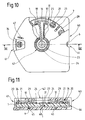
- Figures 10 and 11 show a fourth variant of a sensor disc of the type shown in Figures 4 to 6 but having 12 equal circular sectors, said sensor disc being entirely contained in a housing 40 allowing both to protect the 11 measurement zones 34 and to facilitate its positioning in the measurement device so as to correctly position the first measurement zone to be used, as well as the drive mechanism 6, the contact zones 23, 24, and the isolation zones 7 of the used measurement zones.
- the housing consists of a half-disc and a half-square joined together with a diameter leaving a space inside the housing barely greater than the diameter of the disc 1.
- the housing has an opening 41 giving access to a single measurement area.
- the housing has an opening 42 giving access to the contact zones 23, 24.
- the drive mechanism 6 of the sensor disc consists of a serration on the edge of the disc over its entire periphery; the housing 40 then has another opening 44 located on the same axis as the opening 41 and on the half-square of the housing.
- the opening 41 can also be located at a another location around the periphery of the housing, depending on the arrangement of the drive mechanism of the measuring device intended to cooperate with the serration of the sensor-disc.
- the section in FIG. 11 also shows that the housing 40 makes it possible to maintain the sensor disc in a predetermined spatial position.
- the bottom of the housing has in its center a small axis 48 which comes to cooperate with a blind hole 31 of the disc to allow centering of the latter in the housing 40.
- the free rotation of the disc in the housing is provided by the cooperation of the bosses 10, supported no longer by the disc, but by the housing, and the small centering axis 48.
- a non-return device consists for example of a small pawl 9 carried by the disc 1, intended to come to cooperate with a notched groove in the bottom of the housing.
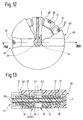
- Figures 12 and 13 show a fifth embodiment in which a circular housing contains a sensor disc of brittle insulating material, each side of which supports a current collector 16 or 17, the two collectors having the same configuration on each side.
- each collector in the shape of a star each branch 28 from a central disc forming a contact area 23 or 24 and extends to the edge of the disc 1 or it constitutes an electrode 20 or 21 of a measurement zone 34, the ionic contact between the electrodes being ensured by the analysis sample, by wetting around the edge of the disc and / or by capillarity through small through orifices 27.
- each circular sector containing a measurement zone 34 is delimited by a radial notch extending from the edge of the disc to a zone of weakening of the coating 29 or 30, making it possible to completely eliminate a zone of measurement used by breakage.
- the device allowing both the spatial positioning of the disc inside the housing and its drive consists of a wheel located on one face of the disc, having an annular shoulder for positioning and a surface provided with radial grooves intended to come to cooperate by friction with a corresponding friction ring of the measuring device.
- the circular housing 40 further comprises, on its external part opposite to that comprising in its center an opening 44 + 42 giving access to both a contact zone 24 and to a drive device 6, a rib 49 located in the axis of the opening 41 of the housing and limited by said opening. This rib has at the center of the disc a second opening 42 giving access to the other contact zone 23.
- FIGS. 14 and 15 represent a sixth embodiment of a sensor, the current collectors of which are arranged on each face of the disc according to the preceding mode, said sensor being contained in a case of the type described in the fourth mode of production.
- the contact zones 23, 24 are in the form of two rings, each being arranged on one face of the disc, having in their center an octagonal section hole passing through the disc and constituting the drive device 6.
- the isolation zones 7 are contiguous and constitute a crown where portions of star branches 28 are uncovered and can be scratched through the opening 47 made in the housing 40.
- the sensor-disc according to the invention makes it possible, after installation in a measuring device, to carry out with a single sensor several measurements before providing for its replacement.
- the measuring device is provided with devices making it possible to connect the current collectors 16, 17 to a electronic measurement and display circuit, to electrically isolate the areas used, to drive the rotating disc, leaving only one measurement area to appear at a time.
- the analysis is carried out by depositing a drop of the sample (for example a drop of blood to measure the glucose level) in a measurement zone 34; once the measurement has been made, the zone used remains on the disc, but is electrically isolated from the other zones which are not yet used, by scratching, by means of a stylus attached to the measuring device, portions of the current collector situated between two zones of measurement.
- a drop of the sample for example a drop of blood to measure the glucose level
- a drop of the sample to be analyzed is deposited on the edge of the disc, the ionic conduction between the two electrodes being ensured by wetting and / or capillarity through the small orifices passing through 27; once the measurement has been made, the area used can be eliminated entirely by breaking a fragment of the disc along line 12. It is also possible, as shown in FIGS. 14 and 15, to mark one of the branches 28 of the star, as indicated for the Figures 1 to 11.
Landscapes
- Chemical & Material Sciences (AREA)
- Life Sciences & Earth Sciences (AREA)
- Organic Chemistry (AREA)
- Health & Medical Sciences (AREA)
- Engineering & Computer Science (AREA)
- Zoology (AREA)
- Wood Science & Technology (AREA)
- Proteomics, Peptides & Aminoacids (AREA)
- Analytical Chemistry (AREA)
- General Engineering & Computer Science (AREA)
- Immunology (AREA)
- Microbiology (AREA)
- Molecular Biology (AREA)
- Biophysics (AREA)
- Physics & Mathematics (AREA)
- Genetics & Genomics (AREA)
- Biochemistry (AREA)
- Bioinformatics & Cheminformatics (AREA)
- Biotechnology (AREA)
- General Health & Medical Sciences (AREA)
- Emergency Medicine (AREA)
- Investigating Or Analysing Biological Materials (AREA)
- Measurement Of The Respiration, Hearing Ability, Form, And Blood Characteristics Of Living Organisms (AREA)
Applications Claiming Priority (2)
| Application Number | Priority Date | Filing Date | Title |
|---|---|---|---|
| FR9305683 | 1993-05-10 | ||
| FR9305683A FR2705150B1 (fr) | 1993-05-10 | 1993-05-10 | Capteur électrochimique à zones multiples sur disque et son application au dosage du glucose. |
Publications (1)
| Publication Number | Publication Date |
|---|---|
| EP0624653A1 true EP0624653A1 (de) | 1994-11-17 |
Family
ID=9447032
Family Applications (1)
| Application Number | Title | Priority Date | Filing Date |
|---|---|---|---|
| EP94106826A Ceased EP0624653A1 (de) | 1993-05-10 | 1994-05-02 | Scheibenförmiger, multizonaler, elektrochemischer Sensor für die Bestimmung von Glykose |
Country Status (7)
| Country | Link |
|---|---|
| US (1) | US5407554A (de) |
| EP (1) | EP0624653A1 (de) |
| JP (1) | JPH06331591A (de) |
| AU (1) | AU669060B2 (de) |
| CA (1) | CA2122690A1 (de) |
| FR (1) | FR2705150B1 (de) |
| RU (1) | RU94015852A (de) |
Families Citing this family (130)
| Publication number | Priority date | Publication date | Assignee | Title |
|---|---|---|---|---|
| US6327031B1 (en) * | 1998-09-18 | 2001-12-04 | Burstein Technologies, Inc. | Apparatus and semi-reflective optical system for carrying out analysis of samples |
| US5628890A (en) * | 1995-09-27 | 1997-05-13 | Medisense, Inc. | Electrochemical sensor |
| US20050069923A1 (en) * | 1996-07-08 | 2005-03-31 | Mullis Kary Banks | Dual bead assays using cleavable spacers and/or ligation to improve specificity and sensitivity including related methods and apparatus |
| CA2301230A1 (en) * | 1996-09-20 | 1998-03-26 | Digital Drives, Inc. | Spatially addressable combinatorial chemical arrays in cd-rom format |
| US6110354A (en) * | 1996-11-01 | 2000-08-29 | University Of Washington | Microband electrode arrays |
| EP0968434A2 (de) * | 1997-02-28 | 2000-01-05 | Burstein Laboratories, Inc. | Labor in einer platte |
| US6036924A (en) | 1997-12-04 | 2000-03-14 | Hewlett-Packard Company | Cassette of lancet cartridges for sampling blood |
| US5997817A (en) | 1997-12-05 | 1999-12-07 | Roche Diagnostics Corporation | Electrochemical biosensor test strip |
| US6391005B1 (en) | 1998-03-30 | 2002-05-21 | Agilent Technologies, Inc. | Apparatus and method for penetration with shaft having a sensor for sensing penetration depth |
| US8480580B2 (en) | 1998-04-30 | 2013-07-09 | Abbott Diabetes Care Inc. | Analyte monitoring device and methods of use |
| US8974386B2 (en) | 1998-04-30 | 2015-03-10 | Abbott Diabetes Care Inc. | Analyte monitoring device and methods of use |
| US8465425B2 (en) | 1998-04-30 | 2013-06-18 | Abbott Diabetes Care Inc. | Analyte monitoring device and methods of use |
| US8346337B2 (en) | 1998-04-30 | 2013-01-01 | Abbott Diabetes Care Inc. | Analyte monitoring device and methods of use |
| US8688188B2 (en) | 1998-04-30 | 2014-04-01 | Abbott Diabetes Care Inc. | Analyte monitoring device and methods of use |
| US6175752B1 (en) | 1998-04-30 | 2001-01-16 | Therasense, Inc. | Analyte monitoring device and methods of use |
| US9066695B2 (en) | 1998-04-30 | 2015-06-30 | Abbott Diabetes Care Inc. | Analyte monitoring device and methods of use |
| US6949816B2 (en) | 2003-04-21 | 2005-09-27 | Motorola, Inc. | Semiconductor component having first surface area for electrically coupling to a semiconductor chip and second surface area for electrically coupling to a substrate, and method of manufacturing same |
| US7416699B2 (en) | 1998-08-14 | 2008-08-26 | The Board Of Trustees Of The Leland Stanford Junior University | Carbon nanotube devices |
| AU6210199A (en) * | 1999-09-27 | 2001-04-30 | Hypoguard Limited | Test device |
| US6428664B1 (en) * | 2000-06-19 | 2002-08-06 | Roche Diagnostics Corporation | Biosensor |
| US7138089B2 (en) * | 2000-07-20 | 2006-11-21 | Hypoguard Limited | Test device for analyzing blood glucose or other analytes in bodily fluids |
| US6827899B2 (en) * | 2000-08-30 | 2004-12-07 | Hypoguard Limited | Test device |
| DE10050883A1 (de) * | 2000-10-13 | 2002-05-16 | It Dr Gambert Gmbh | Vorrichtung zur Bestimmung von ionalen Bestandteilen in Körperflüssigkeiten |
| WO2002084302A2 (en) * | 2000-11-08 | 2002-10-24 | Burstein Technologies, Inc. | Interactive system for analyzing biological samples and processing related information and the use thereof |
| US7061594B2 (en) * | 2000-11-09 | 2006-06-13 | Burstein Technologies, Inc. | Disc drive system and methods for use with bio-discs |
| US7087203B2 (en) * | 2000-11-17 | 2006-08-08 | Nagaoka & Co., Ltd. | Methods and apparatus for blood typing with optical bio-disc |
| US7026131B2 (en) * | 2000-11-17 | 2006-04-11 | Nagaoka & Co., Ltd. | Methods and apparatus for blood typing with optical bio-discs |
| US8641644B2 (en) | 2000-11-21 | 2014-02-04 | Sanofi-Aventis Deutschland Gmbh | Blood testing apparatus having a rotatable cartridge with multiple lancing elements and testing means |
| US20020172980A1 (en) * | 2000-11-27 | 2002-11-21 | Phan Brigitte Chau | Methods for decreasing non-specific binding of beads in dual bead assays including related optical biodiscs and disc drive systems |
| US20040248093A1 (en) * | 2000-11-27 | 2004-12-09 | Coombs James Howard | Magneto-optical bio-discs and systems including related methods |
| US20030003464A1 (en) * | 2000-11-27 | 2003-01-02 | Phan Brigitte C. | Dual bead assays including optical biodiscs and methods relating thereto |
| US6760298B2 (en) * | 2000-12-08 | 2004-07-06 | Nagaoka & Co., Ltd. | Multiple data layer optical discs for detecting analytes |
| WO2002046761A2 (en) * | 2000-12-08 | 2002-06-13 | Burstein Technologies, Inc. | Methods for detecting analytes using optical discs and optical disc readers |
| US6560471B1 (en) | 2001-01-02 | 2003-05-06 | Therasense, Inc. | Analyte monitoring device and methods of use |
| US7200088B2 (en) * | 2001-01-11 | 2007-04-03 | Burstein Technologies, Inc. | System and method of detecting investigational features related to a sample |
| US20020171838A1 (en) * | 2001-05-16 | 2002-11-21 | Pal Andrew Attila | Variable sampling control for rendering pixelization of analysis results in a bio-disc assembly and apparatus relating thereto |
| DE60239132D1 (de) | 2001-06-12 | 2011-03-24 | Pelikan Technologies Inc | Gerät zur erhöhung der erfolgsrate im hinblick auf die durch einen fingerstich erhaltene blutausbeute |
| US9226699B2 (en) | 2002-04-19 | 2016-01-05 | Sanofi-Aventis Deutschland Gmbh | Body fluid sampling module with a continuous compression tissue interface surface |
| AU2002348683A1 (en) | 2001-06-12 | 2002-12-23 | Pelikan Technologies, Inc. | Method and apparatus for lancet launching device integrated onto a blood-sampling cartridge |
| US9795747B2 (en) | 2010-06-02 | 2017-10-24 | Sanofi-Aventis Deutschland Gmbh | Methods and apparatus for lancet actuation |
| ATE485766T1 (de) | 2001-06-12 | 2010-11-15 | Pelikan Technologies Inc | Elektrisches betätigungselement für eine lanzette |
| US7025774B2 (en) | 2001-06-12 | 2006-04-11 | Pelikan Technologies, Inc. | Tissue penetration device |
| EP1404232B1 (de) | 2001-06-12 | 2009-12-02 | Pelikan Technologies Inc. | Gerät und verfahren zur entnahme von blutproben |
| JP4209767B2 (ja) | 2001-06-12 | 2009-01-14 | ペリカン テクノロジーズ インコーポレイテッド | 皮膚の性状の一時的変化に対する適応手段を備えた自動最適化形切開器具 |
| US8337419B2 (en) | 2002-04-19 | 2012-12-25 | Sanofi-Aventis Deutschland Gmbh | Tissue penetration device |
| ATE494837T1 (de) | 2001-06-12 | 2011-01-15 | Pelikan Technologies Inc | Integriertes system zur blutprobenanalyse mit mehrfach verwendbarem probennahmemodul |
| US7981056B2 (en) | 2002-04-19 | 2011-07-19 | Pelikan Technologies, Inc. | Methods and apparatus for lancet actuation |
| US7221632B2 (en) * | 2001-07-12 | 2007-05-22 | Burstein Technologies, Inc. | Optical disc system and related detecting methods for analysis of microscopic structures |
| AU2002326441A1 (en) * | 2001-07-20 | 2003-03-03 | Burstein Technologies, Inc. | Optical analysis disc and related drive assembly for performing interactive centrifugation |
| US20040226348A1 (en) * | 2001-07-24 | 2004-11-18 | Phillip Bruce | Magnetic assisted detection of magnetic beads using optical disc drives |
| US7344894B2 (en) | 2001-10-16 | 2008-03-18 | Agilent Technologies, Inc. | Thermal regulation of fluidic samples within a diagnostic cartridge |
| US20080094974A1 (en) * | 2001-11-09 | 2008-04-24 | Burstein Technologies, Inc. | Optical disc system and related detecting methods for analysis of microscopic structures |
| US6997343B2 (en) * | 2001-11-14 | 2006-02-14 | Hypoguard Limited | Sensor dispensing device |
| US20030111357A1 (en) * | 2001-12-13 | 2003-06-19 | Black Murdo M. | Test meter calibration |
| AU2003202951A1 (en) * | 2002-01-14 | 2003-07-30 | Burstein Technologies, Inc. | Method and apparatus for visualizing data |
| CA2471018A1 (en) * | 2002-01-28 | 2003-08-07 | Burstein Technologies, Inc. | Methods and apparatus for logical triggering of an optical bio-disc |
| US20050002827A1 (en) * | 2002-01-29 | 2005-01-06 | Mcintyre Kevin Robert | Optical discs including equi-radial and/or spiral analysis zones and related disc drive systems and methods |
| CN1625689A (zh) | 2002-01-31 | 2005-06-08 | 长冈实业株式会社 | 通过盘槽以及相关光分析盘触发的方法和系统 |
| US20030169426A1 (en) * | 2002-03-08 | 2003-09-11 | Peterson Timothy A. | Test member orientation |
| US7410468B2 (en) | 2002-04-19 | 2008-08-12 | Pelikan Technologies, Inc. | Method and apparatus for penetrating tissue |
| US7674232B2 (en) | 2002-04-19 | 2010-03-09 | Pelikan Technologies, Inc. | Method and apparatus for penetrating tissue |
| US7901362B2 (en) | 2002-04-19 | 2011-03-08 | Pelikan Technologies, Inc. | Method and apparatus for penetrating tissue |
| US7909778B2 (en) | 2002-04-19 | 2011-03-22 | Pelikan Technologies, Inc. | Method and apparatus for penetrating tissue |
| US7563232B2 (en) | 2002-04-19 | 2009-07-21 | Pelikan Technologies, Inc. | Method and apparatus for penetrating tissue |
| US9314194B2 (en) | 2002-04-19 | 2016-04-19 | Sanofi-Aventis Deutschland Gmbh | Tissue penetration device |
| US7491178B2 (en) | 2002-04-19 | 2009-02-17 | Pelikan Technologies, Inc. | Method and apparatus for penetrating tissue |
| US7244265B2 (en) | 2002-04-19 | 2007-07-17 | Pelikan Technologies, Inc. | Method and apparatus for penetrating tissue |
| US7291117B2 (en) | 2002-04-19 | 2007-11-06 | Pelikan Technologies, Inc. | Method and apparatus for penetrating tissue |
| US7371247B2 (en) | 2002-04-19 | 2008-05-13 | Pelikan Technologies, Inc | Method and apparatus for penetrating tissue |
| US7524293B2 (en) | 2002-04-19 | 2009-04-28 | Pelikan Technologies, Inc. | Method and apparatus for penetrating tissue |
| US8267870B2 (en) | 2002-04-19 | 2012-09-18 | Sanofi-Aventis Deutschland Gmbh | Method and apparatus for body fluid sampling with hybrid actuation |
| US8372016B2 (en) | 2002-04-19 | 2013-02-12 | Sanofi-Aventis Deutschland Gmbh | Method and apparatus for body fluid sampling and analyte sensing |
| US7232451B2 (en) | 2002-04-19 | 2007-06-19 | Pelikan Technologies, Inc. | Method and apparatus for penetrating tissue |
| US7374544B2 (en) | 2002-04-19 | 2008-05-20 | Pelikan Technologies, Inc. | Method and apparatus for penetrating tissue |
| US7713214B2 (en) | 2002-04-19 | 2010-05-11 | Pelikan Technologies, Inc. | Method and apparatus for a multi-use body fluid sampling device with optical analyte sensing |
| US8784335B2 (en) | 2002-04-19 | 2014-07-22 | Sanofi-Aventis Deutschland Gmbh | Body fluid sampling device with a capacitive sensor |
| US9795334B2 (en) | 2002-04-19 | 2017-10-24 | Sanofi-Aventis Deutschland Gmbh | Method and apparatus for penetrating tissue |
| US8579831B2 (en) | 2002-04-19 | 2013-11-12 | Sanofi-Aventis Deutschland Gmbh | Method and apparatus for penetrating tissue |
| US7141058B2 (en) | 2002-04-19 | 2006-11-28 | Pelikan Technologies, Inc. | Method and apparatus for a body fluid sampling device using illumination |
| US7175642B2 (en) | 2002-04-19 | 2007-02-13 | Pelikan Technologies, Inc. | Methods and apparatus for lancet actuation |
| US8221334B2 (en) | 2002-04-19 | 2012-07-17 | Sanofi-Aventis Deutschland Gmbh | Method and apparatus for penetrating tissue |
| US8360992B2 (en) | 2002-04-19 | 2013-01-29 | Sanofi-Aventis Deutschland Gmbh | Method and apparatus for penetrating tissue |
| US7229458B2 (en) | 2002-04-19 | 2007-06-12 | Pelikan Technologies, Inc. | Method and apparatus for penetrating tissue |
| US7331931B2 (en) | 2002-04-19 | 2008-02-19 | Pelikan Technologies, Inc. | Method and apparatus for penetrating tissue |
| US7297122B2 (en) | 2002-04-19 | 2007-11-20 | Pelikan Technologies, Inc. | Method and apparatus for penetrating tissue |
| US7892183B2 (en) | 2002-04-19 | 2011-02-22 | Pelikan Technologies, Inc. | Method and apparatus for body fluid sampling and analyte sensing |
| US8702624B2 (en) | 2006-09-29 | 2014-04-22 | Sanofi-Aventis Deutschland Gmbh | Analyte measurement device with a single shot actuator |
| US7485128B2 (en) | 2002-04-19 | 2009-02-03 | Pelikan Technologies, Inc. | Method and apparatus for penetrating tissue |
| US7717863B2 (en) | 2002-04-19 | 2010-05-18 | Pelikan Technologies, Inc. | Method and apparatus for penetrating tissue |
| US7547287B2 (en) | 2002-04-19 | 2009-06-16 | Pelikan Technologies, Inc. | Method and apparatus for penetrating tissue |
| WO2003088824A2 (en) | 2002-04-19 | 2003-10-30 | Pelikan Technologies, Inc. | Device and method for variable speed lancet |
| US7976476B2 (en) | 2002-04-19 | 2011-07-12 | Pelikan Technologies, Inc. | Device and method for variable speed lancet |
| US7648468B2 (en) | 2002-04-19 | 2010-01-19 | Pelikon Technologies, Inc. | Method and apparatus for penetrating tissue |
| US7582099B2 (en) | 2002-04-19 | 2009-09-01 | Pelikan Technologies, Inc | Method and apparatus for penetrating tissue |
| US7250095B2 (en) * | 2002-07-11 | 2007-07-31 | Hypoguard Limited | Enzyme electrodes and method of manufacture |
| US7265881B2 (en) * | 2002-12-20 | 2007-09-04 | Hewlett-Packard Development Company, L.P. | Method and apparatus for measuring assembly and alignment errors in sensor assemblies |
| US8574895B2 (en) | 2002-12-30 | 2013-11-05 | Sanofi-Aventis Deutschland Gmbh | Method and apparatus using optical techniques to measure analyte levels |
| US7264139B2 (en) * | 2003-01-14 | 2007-09-04 | Hypoguard Limited | Sensor dispensing device |
| EP2238892A3 (de) | 2003-05-30 | 2011-02-09 | Pelikan Technologies Inc. | Vorrichtung zur Entnahme von Körperflüssigkeit |
| ES2490740T3 (es) | 2003-06-06 | 2014-09-04 | Sanofi-Aventis Deutschland Gmbh | Aparato para toma de muestras de fluido sanguíneo y detección de analitos |
| WO2006001797A1 (en) | 2004-06-14 | 2006-01-05 | Pelikan Technologies, Inc. | Low pain penetrating |
| US7604592B2 (en) | 2003-06-13 | 2009-10-20 | Pelikan Technologies, Inc. | Method and apparatus for a point of care device |
| EP1671096A4 (de) | 2003-09-29 | 2009-09-16 | Pelikan Technologies Inc | Verfahren und apparatur für eine verbesserte probeneinfangvorrichtung |
| WO2005037095A1 (en) | 2003-10-14 | 2005-04-28 | Pelikan Technologies, Inc. | Method and apparatus for a variable user interface |
| US7822454B1 (en) | 2005-01-03 | 2010-10-26 | Pelikan Technologies, Inc. | Fluid sampling device with improved analyte detecting member configuration |
| US8668656B2 (en) | 2003-12-31 | 2014-03-11 | Sanofi-Aventis Deutschland Gmbh | Method and apparatus for improving fluidic flow and sample capture |
| US20050150762A1 (en) * | 2004-01-09 | 2005-07-14 | Butters Colin W. | Biosensor and method of manufacture |
| US8828203B2 (en) | 2004-05-20 | 2014-09-09 | Sanofi-Aventis Deutschland Gmbh | Printable hydrogels for biosensors |
| US9820684B2 (en) | 2004-06-03 | 2017-11-21 | Sanofi-Aventis Deutschland Gmbh | Method and apparatus for a fluid sampling device |
| US9775553B2 (en) | 2004-06-03 | 2017-10-03 | Sanofi-Aventis Deutschland Gmbh | Method and apparatus for a fluid sampling device |
| US8211038B2 (en) * | 2004-09-17 | 2012-07-03 | Abbott Diabetes Care Inc. | Multiple-biosensor article |
| US8652831B2 (en) | 2004-12-30 | 2014-02-18 | Sanofi-Aventis Deutschland Gmbh | Method and apparatus for analyte measurement test time |
| JP4735833B2 (ja) * | 2006-01-13 | 2011-07-27 | セイコーエプソン株式会社 | バイオチップ及びバイオセンサ |
| KR100981222B1 (ko) * | 2006-01-31 | 2010-09-10 | 파나소닉 주식회사 | 혈액 센서와 그것을 구비하는 혈액 검사 장치 |
| EP1815785A1 (de) * | 2006-02-02 | 2007-08-08 | Bioception B.V.i.o. | Diagnosegerät in Form einer Kassette zur Diagnose von Flüssigkeit und deren Inhalt |
| EP1967139A1 (de) * | 2007-03-09 | 2008-09-10 | Roche Diagnostics GmbH | Einweg-Punktionsvorrichtung und wiederverwendbare Handhabungsvorrichtung für eine Punktionsvorrichtung |
| US9386944B2 (en) | 2008-04-11 | 2016-07-12 | Sanofi-Aventis Deutschland Gmbh | Method and apparatus for analyte detecting device |
| US8465977B2 (en) * | 2008-07-22 | 2013-06-18 | Roche Diagnostics Operations, Inc. | Method and apparatus for lighted test strip |
| US9375169B2 (en) | 2009-01-30 | 2016-06-28 | Sanofi-Aventis Deutschland Gmbh | Cam drive for managing disposable penetrating member actions with a single motor and motor and control system |
| US8337422B2 (en) * | 2009-07-14 | 2012-12-25 | Becton, Dickinson And Company | Diagnostic test strip having fluid transport features |
| US8337423B2 (en) * | 2009-07-14 | 2012-12-25 | Becton, Dickinson And Company | Blood glucose sensor |
| US8771202B2 (en) | 2010-01-19 | 2014-07-08 | Becton Dickinson And Company | Electrode layout for blood test sensor strip |
| US8956309B2 (en) * | 2010-01-19 | 2015-02-17 | Becton, Dickinson And Company | Sensor strip positioning mechanism |
| US8550295B2 (en) * | 2010-02-22 | 2013-10-08 | Roche Diagnostics Operations, Inc. | Container for dispensing a single test strip |
| US8965476B2 (en) | 2010-04-16 | 2015-02-24 | Sanofi-Aventis Deutschland Gmbh | Tissue penetration device |
| TW201430342A (zh) * | 2013-01-28 | 2014-08-01 | Actherm Inc | 檢測試片之檢測裝置及檢測方法 |
| US10036709B2 (en) | 2014-05-20 | 2018-07-31 | Roche Diabetes Care, Inc. | BG meter illuminated test strip |
| JP6584821B2 (ja) * | 2015-04-30 | 2019-10-02 | 株式会社東芝 | 測定用セル、検出装置および分析装置 |
| US10436736B2 (en) | 2015-12-08 | 2019-10-08 | Endress+Hauser Conducta Gmbh + Co. Kg | Measurement device for measuring a property of a fluid |
| US11054384B1 (en) | 2019-12-23 | 2021-07-06 | Nanodx, Inc. | Sensor system and methods of making |
Citations (3)
| Publication number | Priority date | Publication date | Assignee | Title |
|---|---|---|---|---|
| DE2127142A1 (de) * | 1970-06-08 | 1971-12-16 | Miles Lab | Analysiergerät |
| US4963245A (en) * | 1986-05-02 | 1990-10-16 | Ciba Corning Diagnostics Corp. | Unitary multiple electrode sensor |
| WO1992014836A1 (fr) * | 1991-02-21 | 1992-09-03 | Asulab S.A. | Capteur de mesure de la quantite d'un composant en solution |
Family Cites Families (5)
| Publication number | Priority date | Publication date | Assignee | Title |
|---|---|---|---|---|
| US4978503A (en) * | 1984-06-13 | 1990-12-18 | Ares-Serono Research & Development Limited Partnership | Devices for use in chemical test procedures |
| US5066372A (en) * | 1986-05-02 | 1991-11-19 | Ciba Corning Diagnostics Corp. | Unitary multiple electrode sensor |
| US5128015A (en) * | 1988-03-15 | 1992-07-07 | Tall Oak Ventures | Method and apparatus for amperometric diagnostic analysis |
| JPH0752170B2 (ja) * | 1988-05-27 | 1995-06-05 | ダイキン工業株式会社 | 拡散制限膜保持具収容容器 |
| FR2673183B1 (fr) * | 1991-02-21 | 1996-09-27 | Asulab Sa | Complexes mono, bis ou tris (2,2'-bipyridine substituee) d'un metal choisi parmi le fer, le ruthenium, l'osmium ou le vanadium et leurs procedes de preparation . |
-
1993
- 1993-05-10 FR FR9305683A patent/FR2705150B1/fr not_active Expired - Fee Related
-
1994
- 1994-04-08 US US08/224,778 patent/US5407554A/en not_active Expired - Fee Related
- 1994-05-02 CA CA002122690A patent/CA2122690A1/en not_active Abandoned
- 1994-05-02 JP JP6093452A patent/JPH06331591A/ja active Pending
- 1994-05-02 EP EP94106826A patent/EP0624653A1/de not_active Ceased
- 1994-05-06 AU AU61950/94A patent/AU669060B2/en not_active Ceased
- 1994-05-06 RU RU94015852/14A patent/RU94015852A/ru unknown
Patent Citations (3)
| Publication number | Priority date | Publication date | Assignee | Title |
|---|---|---|---|---|
| DE2127142A1 (de) * | 1970-06-08 | 1971-12-16 | Miles Lab | Analysiergerät |
| US4963245A (en) * | 1986-05-02 | 1990-10-16 | Ciba Corning Diagnostics Corp. | Unitary multiple electrode sensor |
| WO1992014836A1 (fr) * | 1991-02-21 | 1992-09-03 | Asulab S.A. | Capteur de mesure de la quantite d'un composant en solution |
Non-Patent Citations (1)
| Title |
|---|
| LIU ET AL.: "Miniature multiple cathode dissolved oxygen sensor ....", MARINE TECHNOLOGY, vol. 16, 1980, NEW YORK NY, pages 468 - 472 * |
Also Published As
| Publication number | Publication date |
|---|---|
| FR2705150B1 (fr) | 1995-07-21 |
| US5407554A (en) | 1995-04-18 |
| AU669060B2 (en) | 1996-05-23 |
| RU94015852A (ru) | 1996-06-20 |
| CA2122690A1 (en) | 1994-11-11 |
| FR2705150A1 (fr) | 1994-11-18 |
| AU6195094A (en) | 1994-11-17 |
| JPH06331591A (ja) | 1994-12-02 |
Similar Documents
| Publication | Publication Date | Title |
|---|---|---|
| FR2705150A1 (fr) | Capteur électrochimique à zones multiples sur disque et son application au dosage du glucose. | |
| EP0609760B1 (de) | Elektrochemisches System mit mehrzonigem Sensorelement zur Bestimmung von Glukose | |
| US6881578B2 (en) | Analyte concentration determination meters and methods of using the same | |
| EP3829418B1 (de) | Metall-oberflächen-verhältnis einer mikrokanüle | |
| EP0586982B1 (de) | Amperometrisches Messgerät mit einem elektrochemischen Sensor | |
| EP4009865B1 (de) | Körperüberwachungssystem mit einer mikronadel | |
| EP3829436B1 (de) | Multipositionskapsel | |
| EP3829437A1 (de) | Mikronadeleindringungsmanagement | |
| FR2507371A1 (fr) | Ensemble de disque magnetique, cassette destinee a celui-ci, et dispositif d'enregistrement et, ou bien, de reproduction a utiliser avec celui-ci | |
| CH621410A5 (de) | ||
| EP0526602A1 (de) | Rezeptor zur Messung der Quantität eines Bestandteils in Lösung. | |
| EP1162453A1 (de) | Elektrochemischer Sensor mit verbesserter Reproduzierbarkeit | |
| EP4009864B1 (de) | Körperüberwachungssystem mit einer mikronadel | |
| EP0992790B1 (de) | Einfach handzuhabender streifenförmiger elektrochemischer Sensor | |
| EP0969266B1 (de) | Vorrichtung und Verfahren zur Bestimmung der Winkellage von mindestens zwei koaxialen Rädern mit einem einzigen Sensor | |
| EP3460275B1 (de) | Lager für uhrwerk | |
| WO2018215617A1 (fr) | Cartouche de mesure électrochimique | |
| FR3138774A1 (fr) | Procédé de fabrication d’une micro-aiguille en particulier métallisation de la pointe d’une microaiguille. | |
| EP1300194B1 (de) | Kombinierte Vorrichtung zur Behandlung biologischer Mikromatrizen | |
| FR3138320A1 (fr) | Procédé de fabrication d’une micro-aiguille et en particulier métallisation de la pointe d’une microaiguille | |
| EP4031867B1 (de) | Vorrichtung zur entnahme einer probe einer biologischen flüssigkeit | |
| FR3132835A1 (fr) | Capteur à microaiguilles comprenant une base, au moins un module élémentaire de support de microaiguille | |
| EP1185684B1 (de) | Elektrochemischer biosensor und einsatzelement dafür | |
| EP3970857A1 (de) | Fluidsystem, das eine fluidkomponente und eine auf dieser komponente angebrachten instrumentierten vorrichtung umfasst | |
| EP0061810A2 (de) | Messvorrichtung mit einer Elektrode deren Fühlelement fest ist und Verfahren zu deren Herstellung |
Legal Events
| Date | Code | Title | Description |
|---|---|---|---|
| PUAI | Public reference made under article 153(3) epc to a published international application that has entered the european phase |
Free format text: ORIGINAL CODE: 0009012 |
|
| AK | Designated contracting states |
Kind code of ref document: A1 Designated state(s): CH DE DK ES GB IT LI NL SE |
|
| 17P | Request for examination filed |
Effective date: 19941221 |
|
| GRAG | Despatch of communication of intention to grant |
Free format text: ORIGINAL CODE: EPIDOS AGRA |
|
| 17Q | First examination report despatched |
Effective date: 19981119 |
|
| STAA | Information on the status of an ep patent application or granted ep patent |
Free format text: STATUS: THE APPLICATION HAS BEEN REFUSED |
|
| 18R | Application refused |
Effective date: 19990509 |