EP0624718B1 - Valve rotative sphérique pour moteur à combustion interne - Google Patents
Valve rotative sphérique pour moteur à combustion interne Download PDFInfo
- Publication number
- EP0624718B1 EP0624718B1 EP94103967A EP94103967A EP0624718B1 EP 0624718 B1 EP0624718 B1 EP 0624718B1 EP 94103967 A EP94103967 A EP 94103967A EP 94103967 A EP94103967 A EP 94103967A EP 0624718 B1 EP0624718 B1 EP 0624718B1
- Authority
- EP
- European Patent Office
- Prior art keywords
- rotary
- exhaust
- cavities
- drum
- spherical
- Prior art date
- Legal status (The legal status is an assumption and is not a legal conclusion. Google has not performed a legal analysis and makes no representation as to the accuracy of the status listed.)
- Expired - Lifetime
Links
Images


Classifications
-
- F—MECHANICAL ENGINEERING; LIGHTING; HEATING; WEAPONS; BLASTING
- F01—MACHINES OR ENGINES IN GENERAL; ENGINE PLANTS IN GENERAL; STEAM ENGINES
- F01L—CYCLICALLY OPERATING VALVES FOR MACHINES OR ENGINES
- F01L7/00—Rotary or oscillatory slide valve-gear or valve arrangements
- F01L7/10—Rotary or oscillatory slide valve-gear or valve arrangements with valves of other specific shape, e.g. spherical
-
- F—MECHANICAL ENGINEERING; LIGHTING; HEATING; WEAPONS; BLASTING
- F01—MACHINES OR ENGINES IN GENERAL; ENGINE PLANTS IN GENERAL; STEAM ENGINES
- F01L—CYCLICALLY OPERATING VALVES FOR MACHINES OR ENGINES
- F01L7/00—Rotary or oscillatory slide valve-gear or valve arrangements
- F01L7/02—Rotary or oscillatory slide valve-gear or valve arrangements with cylindrical, sleeve, or part-annularly shaped valves
- F01L7/026—Rotary or oscillatory slide valve-gear or valve arrangements with cylindrical, sleeve, or part-annularly shaped valves with two or more rotary valves, their rotational axes being parallel, e.g. 4-stroke
-
- F—MECHANICAL ENGINEERING; LIGHTING; HEATING; WEAPONS; BLASTING
- F01—MACHINES OR ENGINES IN GENERAL; ENGINE PLANTS IN GENERAL; STEAM ENGINES
- F01L—CYCLICALLY OPERATING VALVES FOR MACHINES OR ENGINES
- F01L7/00—Rotary or oscillatory slide valve-gear or valve arrangements
- F01L7/16—Sealing or packing arrangements specially therefor
-
- F—MECHANICAL ENGINEERING; LIGHTING; HEATING; WEAPONS; BLASTING
- F02—COMBUSTION ENGINES; HOT-GAS OR COMBUSTION-PRODUCT ENGINE PLANTS
- F02F—CYLINDERS, PISTONS OR CASINGS, FOR COMBUSTION ENGINES; ARRANGEMENTS OF SEALINGS IN COMBUSTION ENGINES
- F02F7/00—Casings, e.g. crankcases
- F02F7/006—Camshaft or pushrod housings
- F02F2007/0063—Head bolts; Arrangements of cylinder head bolts
Definitions
- the present invention relates to an internal combustion engine of the piston and cylinder type and more particularly to an improved spherical rotary valve assembly for use with a rotary valve internal combustion engine for the introduction of the fuel/air mixture to the cylinder and the evacuation of exhaust gases.
- the hardware associated with the efficient operation of conventional internal combustion engines having spring-loaded valves includes such items as springs, cotters, guides, rocker shafts and valves themselves which are usually positioned in the cylinder head such that they normally operate in a substantially vertical position with their opening discending into the cylinder for the introduction or venting or evacuation of gases.
- the cam shaft In the standard internal combustion engine, the cam shaft is rotated by the crankshaft by means of a timing belt or chain. The operation of this cam shaft and the associated valves operated by the cam shaft presents the opportunity to decrease engine efficiency through friction associated with the operation of the various elements.
- Applicant has developed a rotary valve assembly for use with internal combustion engines; U.S. Patent 4,944,261; U.S. Patent 4,953,527; U.S. Patent 4,989,558 and U.S. Patent 4,976,232.
- Applicant's spherical rotary valve assembly eliminates much of the hardware associated with the conventional and standard poppet valve assembly used in conventional automobiles.
- the advantages of Applicant's spherical rotary valves have been set forth in the prior cited United States patents.
- the present application is directed towards an improved spherical rotary valve for use with Applicant's assembly which allows the intake valve to be fed with a fuel/air mixture from both sides of the intake valve in order to improve the breathing of the engine and the charging of the cylinder with the fuel/air mixture; and permits the exhaust valve to be evacuated from both sides of the valve to improve the evacuation of the spent mixture and to simultaneously decrease the operating temperature of the exhaust rotary valve to further decrease emissions.
- An object of the present invention is to provide for a novel and uniquely improved spherical rotary valve for use with a rotary valve assembly for an internal combustion engine.
- Another object of the present invention is to provide for a novel and uniquely improved spherical rotary valve which permits the intake valve to be fed with a fuel and air mixture simultaneously from both sides of the valve.
- Another object of the present invention is to provide for a novel and uniquely improved spherical rotary valve for use with a rotary valve assembly for an internal combustion engine in which the exhaust valve is evacuated from both sides of the valve to improve the evacuation of spent gases from the cylinder and to maintain the temperature of the exhaust valve at a lower temperature.
- a still further object of the present invention is to provide for a novel and uniquely improved spherical rotary valve for use with a rotary valve assembly for internal combustion engines in which the weight of the improved rotary valves is decreased.
- a further object of the present invention is to provide for a novel and uniquely improved spherical rotary valve for use with a rotary valve assembly for internal combustion engines in which the internal passageways of the spherical rotary valve improve the introduction of the fuel/air mixture to the cylinder and improve the evacuation of the spent gases from the cylinder.
- An improved spherical rotary valve for use with an internal combustion engine with improved sealing means which permits the introduction of fuel/air mixture into the cylinder from both lateral sides of the intake spherical rotary valve and permits the evacuation of the spent exhaust gases from the cylinder from both sides of the exhaust spherical rotary valve, the exhaust spherical rotary valve having the capability of providing additional impetus to the flow of exhaust gases to the exhaust manifold.
- Intake spherical drum 10 is defined by a spherical section formed by two parallel sidewalls 14 and 16 disposed about the spherical center, thereby defining a spherical circumferential end wall 12.
- Sidewalls 14 and 16 respectively have depending inwardly therefrom, circular doughnut-shaped cavities 18 and 20.
- Circular doughnut-shaped cavities 18 and 20 are separated within intake spherical drum 10 by a partition wall 22 positioned within intake spherical drum 10 an equi distance from annular sidewalls 14 and 16.
- Partition wall 22 has positioned centrally therethrough, a shaft mounting element 24, the length of which is complimentary with the width of spherical end wall 12.
- Central shaft mounting element 24 has an axial throughbore 26 positioned therethrough.
- Central shaft mounting element 24 and axial throughbore 26 provide the means for mounting intake spherical drum 10 on a centrally-disposed shaft 28 (not shown) to provide for the rotational disposition of intake spherical drum 10 for the introduction of fuel and air mixture into an automotive cylinder as more further described hereafter.
- Spherical circumferential end wall 12 has positioned on its surface an aperture 30 for communication with circular doughnut-shaped cavities 18 and 20.
- Partition wall 22 has a passageway defined therethrough for communication between circular doughnut-shaped cavities 18 and 20. This passageway 32 being positioned in partition wall 22 adjacent aperture 30 in spherical circumferential end wall 12.
- both circular doughnut-shaped cavities 18 and 20 will be in communication with a source of fuel/air mixture or air mixture from an intake manifold, for introduction into the cylinder of an internal combustion engine.
- Intake spherical drum 10 can therefore be fed the fuel/air mixture or air mixture from both sides of the drum.
- Aperture 30 in spherical end wall 12 will communicate with the inlet opening of the cylinder of the internal combustion engine as a result of the rotation of intake spherical drum 10 on shaft 28.
- the intake aperture will permit the fuel/air mixture or air mixture, in the case of fuel-injected engines, to pass from circular doughnut-shaped cavities 18 and 20 through aperture 30 and into the cylinder.
- spherical intake drum 10 will move the intake aperture 30 away from the inlet to the cylinder with the spherical circumferential end wall 12 of intake spherical drum 10 causing a seal with the inlet to the cylinder, thus interrupting the flow of the fuel/air mixture into the cylinder.
- the fuel air mixture or air mixture will continue to flow from the intake manifold into circular doughnut-shaped cavities 18 and 20 of intake spherical drum 10 for introduction into the cylinder on the next rotation of the spherical intake drum 10 when intake aperture 30 again becomes complimentary with the inlet to the chamber.
- Exhaust spherical drum 40 is defined by a spherical section formed by two (2) parallel sidewalls 44 and 46 disposed about the spherical center, thereby defining a spherical circumferential end wall 42. Sidewalls 44 and 46, respectively, have depending inwardly therefrom, cavities 48 and 50. Cavities 48 and 50 are separated within exhaust spherical drum 40 by a partition wall 52 positioned within exhaust spherical drum 40.
- Partition wall 52 has positioned centrally therethrough a shaft mounting element 54, the length of which is complimentary with the width of spherical end wall 42.
- Central shaft mounting element 54 has an axial throughbore 56 positioned therethrough.
- Central shaft mounting element 54 and axial throughbore 56 provide the means for mounting exhaust spherical drum 40 on a centrally-disposed shaft 28 (not shown) to provide for the rotational disposition of exhaust spherical drum 40 for the evacuation of spent gases from an automotive cylinder as more further described hereafter.
- Spherical circumferential end wall 42 has positioned on its surface, an aperture 60 for communication with cavities 48 and 50.
- Partition wall 52 has a passageway defined therethrough for communication between cavities 48 and 50. This passageway 62 is positioned in the partition wall 52 adjacent aperture 60 in spherical circumferential end wall 42.
- both cavities 48 and 50 will be in communication with an exhaust manifold for the evacuation of spent gases from the cylinder of an internal combustion engine.
- Exhaust spherical drum 40 can therefore evacuate the spent gases from a cylinder utilizing both sides of the drum.
- Aperture 60 and spherical end wall 42 in operation, will communicate with the outlet opening of the cylinder of the internal combustion engine as a result of the rotation of the exhaust spherical drum 40 on shaft 58.
- the exhaust aperture will permit the spent gases to pass from the cylinder, through aperture 60, and thence cavities 48 and 50 to the exhaust manifold.
- exhaust spherical drum 40 will move the exhaust aperture 60 away from the outlet to the cylinder with spherical circumferential end wall 42 of exhaust spherical drum 40 causing a seal with the outlet from the cylinder, thus, interrupting the evacuation of the spent gases from the cylinder.
- the cylinder With the exhaust spherical drum 40 in the closed or interrupted state, the cylinder would undergo its charging and compression/power stroke, and the further rotation of the exhaust spherical drum 40 would bring aperture 60 into contact with the exhaust outlet of the cylinder so as to permit the spent gases to be released from the cylinder during the exhaust stroke, through the outlet port of the cylinder, through aperture 60, and thence along cavities 48 and 50 to the exhaust manifold.
- cavities 48 and 50 would vary in depth from annular sidewalls 44 and 46 to partition wall 52 in order to encourage the evacuation of exhaust gases.
- Partition wall 52 would define the maximum depth in cavities 48 and 50 immediately adjacent the edge of aperture 60 which would rotate into initial alignment with outlet opening of the cylinder.
- the depth of cavities 48 and 50 would decrease such that there would be a plug 49 and 51 formed in cavities 48 and 50 adjacent the opposite edge of aperture 60. This opposite edge of aperture 60 being that portion which is last in communication with the outlet opening of the cylinder during rotation.
- the incline within cavities 48 and 50 could be gradually helical shaped or a severe upslope proximate to plugs 49 and 51.
- the purpose is to provide a thrust effect to encourage rapid evacuation of exhaust gases to the manifold. It should be understood that the exhaust valve would also function with cavities 48 and 50 at a fixed depth.
- Plugs 49 and 51 are a preferrable embodiment in order to impart additional thrust to the exhaust gases.
- spherical rotary valve The concept of the spherical rotary valve is to eliminate the need for push-rod valves and their associated hardware and to provide a means for charging the cylinder for its power stroke and evacuating the cylinder during its exhaust stroke.
- intake spherical drum 10, and in particular, cavities 18 and 20 are in constant communication with the incoming fuel/air mixture from inlet port 114 from the carburetor and this fuel/air mixture in cavities 18 and 20 is introduced into the cylinder when inlet aperture 30 comes into rotational alignment with the inlet port in lower half of the cylinder head as described hereafter.
- arcuate circumferential periphery of end wall 12 serves to seal the inlet port of the cylinder.
- the arcuate circumferential periphery of end wall 42 of exhaust spherical drum 40 maintains a seal on the exhaust port of the cylinder until exhaust aperture 60 on the arcuate circumferential periphery of exhaust spherical drum 40 comes into rotational alignment with the exhaust port of the cylinder positioned in the lower half of the cylinder head.
- the exhaust stroke of the piston then forces the evacuation of the gases through the exhaust port into cavities 48 and 50 of exhaust spherical drum 40 and thence to the exhaust manifold 120.
- intake aperture 30 on intake spherical drum 10 and exhaust aperture 60 on exhaust spherical drum 40 is done with respect to the power strokes and exhaust strokes of the piston within the cylinder and the timing requirements of the engine.
- FIG. 8 there is shown a side sectional view of the cylinder and cylinder head with internal piston in conjunction with the intake spherical drum 10.
- the cylinder and piston and block are similar to that of a conventional internal combustion engine.
- an engine block 100 having disposed therein a cylinder cavity 102 there being positioned within cylinder cavity 102, a reciprocating piston 104 which is secured to a crankshaft 103 and which moves in a reciprocating action within cylinder cavity 102.
- the cylinder cavity itself is surrounded by a plurality of enclosed passageways 106 designed to permit the passage therethrough of a cooling fluid to maintain the temperature of the engine.
- Applicant's engine head is a split head comprised of a lower section 110 which is secured to the engine block 100 and contains an intake port 108 for cylinder 102.
- Intake port 108 is positioned in a hemispherical drum-accommodating cavity 107 defined by the inner section of two perpendicular parallel planes in order to accommodate the positioning of intake spherical drum 10.
- the upper half 112 of the split head assembly also contains a hemispherical drum-accommodating cavity 113 defined by the inner section of two parallel planes in order to define a cavity for receipt of the upper half of intake spherical drum 10.
- intake spherical drum 10 is rotationally encapsulated within the cavity defined by the two halves of the split head assembly.
- a sealing mechanism 116 as described hereafter is positioned about inlet port 108 to cylinder cavity 102 in order to provide an effective seal during the rotational disposition of intake spherical drum 10. Sealing mechanism 116 provides an effective seal with the circumferential periphery of end wall 12 of intake spherical drum 10.
- cavities 18 and 20 on intake spherical drum 10 are continually charged with a fuel/air mixture through inlet port 114.
- This fuel/air mixture is not introduced into cylinder cavity 102 until intake aperture 30 comes into rotational alignment with inlet port 108 to the cylinder 120.
- Sealing mechanism 116 cooperates with the arcuate circumferential periphery 12 of intake spherical drum 10 to provide the effective gas tight seal to ensure the fuel/air mixture passes from cavities 18 and 20 through inlet port 108 and into cylinder cavity 102. In normal operation, this introduction occurs with the downward movement of piston 104 during the intake stroke thus charging the cylinder with the fuel/air mixture.
- intake spherical drum 10 As soon as the inlet aperture 30 has been closed such that it no longer is in alignment with inlet port 108 to the cylinder, the arcuate spherical circumferential periphery 12 of intake spherical drum 10 would seal the inlet port in cooperation with seal 116 in preparation for the power stroke of piston 104 and the ignition of the fuel/air mixture.
- the rotation of intake spherical drum 10 is accomplished by means of shaft 28 upon which intake spherical drum 10 is mounted. Shaft 28 in communication with a timing chain or other similar device and the crankshaft to which the pistons 104 are mounted ensures the appropriate timing of the opening and closing of inlet port 108 by means of alignment with inlet aperture 30 on intake spherical drum 10.
- Exhaust spherical drum 40 is disposed within the same engine block 100 having a cylinder cavity 102 disposed therein in a reciprocating piston 104 within the cylinder cavity 102. Lower and upper heads 110 and 112 are secured to the engine block 100. Exhaust spherical drum 40 is rotationally disposed within the lower half and upper half 110 and 112 of the split head assembly in a drum accommodating cavity 107 and 113 similar to the intake spherical drum 10. Exhaust spherical drum 40 is in communication with an exhaust port 109 for cylinder cavity 102.
- piston 104 In the exhaust mode, piston 104 has completed its power stroke, thus compressing and igniting the fuel/air mixture within the cylinder.
- This power stroke is accomplished with the arcuate spherical circumferential periphery of intake spherical drum 10 and exhaust spherical drum 30 providing the required sealing closure of the respective intake port 108 and exhaust port 109.
- the ignition of the fuel/air mixture serves to drive piston 104 downwardly within cylinder cavity 102 and thence piston 104 begins its ascent in the exhaust stroke.
- Exhaust spherical drum 40 rotating on shaft 28 and in timing communication with the crankshaft rotates to bring aperture 60 on the spherical periphery of exhaust drum 40 in communication with exhaust port 109.
- a conduit passageway is defined through the exhaust spherical drum 40 from exhaust port 109 at the top of the cylinder head with the spent gases being exhausted from the cylinder through exhaust port 109, through aperture 60, and into cavities 48 and 50. Thence to exhaust conduit 120 through chambers 121 and 123 on opposing sides of exhaust valve 40 which exit to the exhaust manifold and to the ambient atmosphere (see Figure 7).
- the initial opening of exhaust spherical drum 40 introduces spent gases into cavities 48 and 50 at the point where their depth is greatest. As previously explained, cavities 48 and 50 gradually decrease in depth until a seal is formed by plug walls 49 and 51. This design serves to accelerate the exhaust gases through spherical exhaust drum 40 in order to hasten the evacuation of cylinder cavity 102.
- Figure 9 is a perspective view of a paired intake spherical drum 10 and exhaust spherical drum 40 positioned within the lower section 110 of the split head assembly with respect to a single cylinder.
- each bank of cylinders would have a similarly-positioned spherical rotary valve assembly associated therewith.
- Another embodiment of the invention would be to provide the intake spherical drums 10 and the exhaust spherical drums 40 would be positioned on a single shaft if the size of the engine were such so that the twin feeding of the intake valve and the twin exhausting of the exhaust valve could be accomplished without affecting the structure integrity of the engine.
- Shaft 28 and rotary spherical drums 10 and 40 are supported in a split head assembly by a plurality of bearing surfaces 130.
- Spherical drums 10 and 40 are machined as is the drum accommodating cavities 107 and 113, the tolerances between the spherical drums and the cavities being approximately 1/1000th of an inch.
- Figure 10a, b, c and d illustrates the manner in which the exhaust gases are evacuated from the cylinder through exhaust drum 40 and thence to the exhaust manifold.
- Figure 10 illustrates the manner in which the airflow exits cylinder 102 through exhaust outlet 109 and through aperture 60 on the spherical periphery of exhaust drum 40, thus entering cavities 48 and 50 of exhaust drum 40.
- the spent exhaust gases then exit cavities 48 and 50 by way of exhaust chambers 121 and 123, respectively (see Figure 7).
- These exhaust gases are given a final impetus by means of plugs 49 and 51 immediately prior to the exhaust process commencing anew with the alignment of aperture 60 with exhaust port 109.
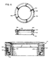
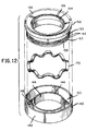
- FIG 11 is a side exploded view illustrating sealing means 116 and Figure 12 is an exploded perspective view of sealing means 116.
- the description of sealing means 116 is made herein with respect to the rotary intake valve 10, but sealing means 116 is of the same design and serves the same purpose and function with respect to its relationship with the rotary exhaust valve 40.
- Sealing means 116 is comprised of two primary members.
- a lower receiving ring 140 is configured to be received within annular groove 138 in the lower half of the split head assembly and circumferentially positioned about inlet port 108.
- Inner circumferential wall 144 and outer circumferential wall 142 are secured by a planar circumferential base 148 thereby defining an annular receiving groove 150 for receipt of the upper valve seal ring 152.
- Upper valve seal ring 152 has a centrally-disposed aperture 154 in alignment with aperture 146 and lower receiving member 140.
- the outer wall 153 of upper valve seal 152 is stepped inwardly from upper surface 156 to lower surface 158 in order to define an annular groove 160 for receipt of a blast ring 162.
- Upper valve seal member 152 is designed to fit within annular groove 150 in lower valve seal receiving member 140.
- the upper surface 156 of upper valve seal ring 152 is curved inwardly towards the center of aperture 154, the upper surface having an annular indent 164 for the receipt of a carbon insert lubricating ring 166.
- Carbon insert lubricating ring 166 extends above upper surface 156 of upper valve seal ring 152 and ontacts the spherical peripheral surface of the rotary intake valve 10.
- the curvature of upper surface 156 is such that it conforms to the peripheral curvature of intake rotary valve 10 with carbon insert lubricating ring 166 in intimate contact with the peripheral surface of rotary intake valve 10.
- annular beveled springs 170 positioned in the annular receiving groove 150 below upper valve seal ring 152.
- the pressure to be maintained upwardly on the upper valve seal ring 152 is in the range of between 1 to 4 ounces. As such, this pressure can be accomplished by either a single bevel spring located in annular receiving groove 150 or a plurality of annular beveled springs.
- Upper valve seal ring 152 has positioned about annular groove 160, a blast ring 162 which functions similar to a piston ring associated with a piston.
- Blast ring 162 serves to provide additional sealing contact between valve seal 116 and the peripheral surface of rotary intake valve 10 and the rotary exhaust valve during the compression and power stroke.
- the increased gas pressure within the cylinder and within annular groove 150 will increase the pressure below the blast ring 162 which forms a seal with the outer circumferential wall 142 preventing the escape of gases, and yet providing an upward force on upper valve seal ring 152, thus forcing a better contact seal between the carbon insert ring 164 and the peripheral surface of rotary intake valve 10.
- the same interaction will occur with the valve seal associated with rotary exhaust valve 40.
- the carbon insert ring 64 will be maintained in contact with the rotary exhaust valve by means of beveled springs positioned in annular groove 150.
- sealing means 116 provides for an intimate seal with the rotary intake and rotary exhaust valve and in fact, is the only contact with the intake rotary valve or exhaust rotary valve during the course of its revolution within the drum accommodating cavities. This significantly reduces the number of mechanical parts within the engine and thereby reduces the friction encountered in the operation of the engine.
Landscapes
- Engineering & Computer Science (AREA)
- Mechanical Engineering (AREA)
- General Engineering & Computer Science (AREA)
- Taps Or Cocks (AREA)
- Cylinder Crankcases Of Internal Combustion Engines (AREA)
- Valve-Gear Or Valve Arrangements (AREA)
- Fuel-Injection Apparatus (AREA)
Claims (10)
- Un système à valve rotative destiné aux moteurs à combustion interne du type à cylindre et piston, ce système à valve rotative sphérique comprenant:caractérisé en ce que les cavités réservoir (115, 117) de la valve rotative d'admission (10) et les cavités d'évacuation (121, 123) de la valve rotative d'échappement (40) sont pratiquées sur les deux côtés de ladite première cavité de réception de tambour (107) de ladite valve rotative d'admission (10) et sur les deux côtés de ladite seconde cavité de réception de tambour (113) desdites valves rotatives d'échappement (40) dans les portions supérieure et inférieure (110, 112) de la tête de cylindre, et en ce que les cavités d'allure torique (18, 20, 48, 50) sont pratiquées dans les deux desdites parois latérales (14, 16, 44, 46) des valves rotatives d'admission (10) et des valves rotatives d'échappement (40).une tête de cylindre amovible en deux portions pouvant être fixée au moteur à combustion interne, cette tête de cylindre amovible en deux portions comprenant une portion de tête de cylindre supérieure et une portion de tête de cylindre inférieure (112, 110), ces portions supérieure et inférieure de tête de cylindre, quand elles sont fixées au dit moteur à combustion interne, définissant deux cavités (107, 113) radialement alignées avec les cylindres (102) dudit moteur à combustion interne, lesdites cavités définissant une pluralité de premières cavités de réception de tambours (107) destinées à recevoir des valves rotatives d'admission (10) alignées radialement, lesdites secondes cavités radialement alignées (113) définissant une pluralité de secondes cavités de réception de tambours (113) destinées à recevoir une pluralité de valves rotatives d'échappement (40) alignées radialement, ladite portion inférieure de tête de cylindre (110) et ladite pluralité de premières cavités de réception de tambours (107) ayant un orifice d'admission (108) en communication avec ledit cylindre (102), ladite portion inférieure (110) de tête de cylindre et lesdites secondes cavités de réception de tambour (113) ayant un orifice de sortie (109) en communication avec ledit cylindre (102);des moyens d'étanchéisation (116) associés auxdits orifices d'entrée et de sortie (108, 109);un premier passage (114) pour l'introduction d'un mélange air / carburant dans ladite tête de cylindre par l'intermédiaire d'une cavité réservoir (115, 117) voisine d'au moins un côté de ladite première cavité de réception du tambour (107) et de ladite valve rotative d'admission (10) et un second passage (120) pour l'évacuation des gaz d'échappement hord dudit cylindre (102) par l'intermédiaire d'une cavité d'évacuation (121, 123) voisine d'au moins un côté de ladite seconde cavité de réception de tambour (113) et de ladite valve rotative d'échappement (40);un premier arbre (28) taurillonné sur des surfaces d'appui (130) à l'intérieur de ladite première cavité (107) radialement alignée avec lesdits cylindres dudit moteur à combustion interne, ladite valve rotative d'admission étant montée sur ledit premier arbre (28);un second arbre (28) taurillonné sur lesdites surfaces d'appui (130) à l'intérieur de ladite cavité alignée radialement (113), sur ledit second arbre étant positionnée une pluralité desdites valves rotatives d'échappement (40);ladite valve rotative d'admission (10) et ladite valve rotative d'échappement (40) comportant chacune une section sphérique délimitée par deux plans parallèles sur une sphère, lesdits plans étant disposés symétriquement par rapport au centre de ladite sphère, ce qui définit une périphérie sphérique (12, 42) et des parois latérales planes (14, 16; 44, 46), lesdites valves rotatives d'admission (10) montées sur ledit premier arbre (28) dans ladite pluralité de cavités de réception de tambours (107) étant en contact hermétique aux gaz avec ledit orifice d'entrée (108), chacune desdites valves rotatives d'échappement (40) montées sur ledit arbre (28) dans ladites pluralité de cavités de réception de tambours (113) étant en contact hermétique aux gaz avec ledit orifice de sortie (109), ladite valve rotative d'admission (10) comportant sur sa périphérie sphérique (12) un passage (30) pour l'introduction et l'interruption du mélange air / carburant dans ledit moteur, ledit passage (30) étant en communication avec au moins une cavité d'allure torique (18, 20) pratiquée dans l'une des parois latérales (14, 16) desdites valves rotatives d'admission (10), ladite cavité d'allure torique (18, 20) étant en communication avec la cavité réservoir (115, 117) adjacente pratiquée dans ladite portion inférieure (110) de la tête de cylindre, ladite cavité réservoir adjacente (115, 117) étant en communication avec ledit passage (114) en vue de l'introduction dudit mélange air / carburant dans ledit cylindre (102) depuis au moins un côté de ladite valve rotative d'admission (10), ladite valve rotative d'échappement (40) comportant positionné sur sa périphérie sphérique (42) un passage (60) pour l'évacuation et l'interruption des gaz d'échappement provenant dudit cylindre (102), ladite valve rotative d'échappement (40) comportant, pratiquées dans lesdites parois latérales planes (44, 46), au moins une cavité d'allure torique (48, 50) en communication avec ledit passage (60) de sa périphérie sphérique (42), ladite cavité d'allure torique (48, 50) étant en communication avec la cavité d'évacuation adjacente (121, 123), pratiquée dans ladite portion inférieure (110) de tête de cylindre, lesdites cavités d'évacuation adjacentes (121, 123) étant en communication avec ledit second passage (120) pour l'évacuation des gaz d'échappement provenant du cylindre (102),
- Un système à valve rotative selon la revendication 1, dans lequel lesdits moyens d'étanchéisation comprennent:une bague de réception (140) de section transversale sensiblement circulaire, dans laquelle est délimitée une rainure de réception annulaire (150), ladite bague de réception (140) étant montée dans ladite tête de cylindre antour dudit orifice d'entrée (108) par rapport à ladite valve rotative d'admission (10) et autour dudit orifice de sortie (109) par rapport à ladite valve rotative d'échappement (40), ladite bague de réception (140) étant traversée par une ouverture (146) coïncidant avec ledit orifice à entrée (108) ou avec ledit orifice de sortie (109);une bague de contact (152) étant montée amovible à l'intérieur de ladite rainure de réception annulaire (150) de ladite bague de réception (140), ladite bague de contact (152) ayant une surface supérieure arrondie (156) se conformant à ladite périphérie sphérique de ladite valve d'admission (10) ou de ladite valve d'échappement (40), ladite bague de contact (152) étant traversée par une ouverture (154) coïncidant avec ladite ouverture (146) de ladite bague de réception (140) et ledit orifice d'entrée (108) ou ledit orifice de sortie (109);des moyens de pression élastique (170) positionnés dans ladite rainure annulaire de réception (150) de ladite bague de réception (140), positionnés au-dessous de ladite bague de contact (152) et exerçant sur ladite bague de contact une pression dirigée vers le haut;des moyens d'étanchéisation (162) positionnés autour de ladite bague de contact (152), en contact avec ladite paroi extérieure (142) de ladite rainure annulaire de réception (150);et un passage de communication (163) entre ledit orifice d'entrée (108) ou ledit orifice de sortie (109) et lesdits moyens d'étanchéisation (162) montés sur ladite bague de contact (152).
- Un système à valve rotative selon la revendication 2, dans lequel ladite surface arrondie (156) de ladite bague de contact (152) correspondant à ladite surface périphérique de ladite valve rotative d'admission (10) ou de ladite valve rotative d'échappement contient, positionné à l'intérieur, un insert en fibres de carbone (166).
- Un système à valve rotative selon la revendication 2 ou 3, dans lequel lesdits moyens d'étanchéisation (162) de ladite bague de contact (152) comprennent une ou plusieurs couronnes élastiques (162) montées amovibles autour de ladite bague de contact (152), lesdites couronnes élastiques (162) assurant un contact intime avec ladite paroi extérieure (142) de ladite rainure annulaire de réception (150) de ladite bague de réception.
- Un système à valve rotative selon l'une des revendications 2 à 4, dans lequel les moyens élastiques (170) positionnés dans ladite rainure annulaire de réception (150) au-dessous de ladite bague de contact (152) comprennent un ou plusieurs ressorts chanfreinés (170) créant une pression dirigée vers le haut sur ladite bague de contact (152) rencontrant ladite surface arrondie (156) de ladite bague de contact (152) avec ladite surface périphérique de ladite valve rotative d'admission (10) ou de ladite valve rotative d'échappement (40).
- Un système à valve rotative selon l'une des revendications 2 à 5 dans lequel la bague de contact (152) est réalisée en fibres de carbone.
- Un système à valve rotative selon l'une des revendications 1 à 6, dans lequel ladite valve rotative d'admission (10) destinée à être utilisée dans ledit moteur à combustion interne à valve rotative comprend un corps en forme de tambour à section sphérique délimité par deux plans parallèles sur une sphère, disposés symétriquement par rapport au centre de ladite sphère en définissant ainsi une périphérie sphérique (12) et des parois latérales planes (14, 16), comportant en son centre une ouverture de réception d'arbre (26) qui la traverse radialement, dans chacune desdites parois latérales (14, 16) dudit corps en forme de tambour étant pratiquée une cavité d'allure torique (18, 20), de chaque côté de ladite ouverture de réception d'arbre (26). Lesdites cavités d'allure torique (18, 20) étant séparées par une cloison de séparation (22), ladite cloison de séparation (22) comportant un canal (32) s'étendant entre lesdites cavités d'allure torique (18, 20), ledit canal (32) étant adjacent au passage (30) pratiqué dans ladite périphérie sphérique (12).
- Un système à valve rotative selon l'une des revendications 1 à 7, destiné à être utilisé dans un moteur à combustion interne à valve rotative, comprenant un corps en forme de tambour à section sphérique délimité par deux plans parallèles sur une sphère disposés symétriquement par rapport au centre de ladite sphère, ledit corps en forme de tambour délimitant ainsi une périphérie sphérique (42) et des parois latérales planes (44, 45), ledit corps en forme de tambour comprenant de plus une ouverture centrale de réception d'arbre (56) le traversant radialement, dans chacune desdites parois latérales (44, 46) dudit corps en forme de tambour étant pratiquées des cavités d'allure torique (48, 50) disposées autour de ladite ouverture de réception d'arbre (56), lesdites cavités d'allure torique (48, 50) étant séparées par une cloison de séparation (52), ladite cloison de séparation (52) étant traversée par un canal (62), ledit canal (62) dans ladite cloison de séparation (52) étant adjacent au passage (60) pratiqué dans ladite périphérie sphérique (42).
- Un système à valve rotative selon la revendication 8, dans lequel, dans lesdites cavités d'allure torique (48, 50) dans chacune des parois latérales (44, 46) est positionnée une cloison (49) formant bouchon s'étendant radialement vers l'extérieur depuis l'ouverture de réception d'arbre (56) jusqu'à ladite périphérie sphérique (42), ladite cloison formant bouchon (49) étant située à proximité dudit canal de la cloison de séparation (52), ladite cloison formant bouchon (49) conférant une poussée additionnelle pour l'évacuation desdits gaz d'échappement.
- Un système à valve rotative selon la revendication 9, dans lequel ladite cloison formant bouchon dans lesdites cavités d'allure torique sont graduellement inclinées vers le haut à partir de ladite cloison de séparation.
Applications Claiming Priority (2)
| Application Number | Priority Date | Filing Date | Title |
|---|---|---|---|
| US08/060,358 US5361739A (en) | 1993-05-12 | 1993-05-12 | Spherical rotary valve assembly for use in a rotary valve internal combustion engine |
| US60358 | 1993-05-12 |
Publications (2)
| Publication Number | Publication Date |
|---|---|
| EP0624718A1 EP0624718A1 (fr) | 1994-11-17 |
| EP0624718B1 true EP0624718B1 (fr) | 1998-02-04 |
Family
ID=22028990
Family Applications (1)
| Application Number | Title | Priority Date | Filing Date |
|---|---|---|---|
| EP94103967A Expired - Lifetime EP0624718B1 (fr) | 1993-05-12 | 1994-03-15 | Valve rotative sphérique pour moteur à combustion interne |
Country Status (32)
| Country | Link |
|---|---|
| US (1) | US5361739A (fr) |
| EP (1) | EP0624718B1 (fr) |
| JP (1) | JP3493054B2 (fr) |
| KR (1) | KR100285222B1 (fr) |
| CN (1) | CN1041451C (fr) |
| AT (1) | ATE163067T1 (fr) |
| AU (1) | AU668289B2 (fr) |
| BG (1) | BG61884B1 (fr) |
| BR (1) | BR9401930A (fr) |
| CA (1) | CA2115502C (fr) |
| CZ (1) | CZ287183B6 (fr) |
| DE (1) | DE69408360T2 (fr) |
| DK (1) | DK0624718T3 (fr) |
| EG (1) | EG20404A (fr) |
| ES (1) | ES2113005T3 (fr) |
| FI (2) | FI106879B (fr) |
| GR (1) | GR3026190T3 (fr) |
| HU (1) | HU217472B (fr) |
| IL (1) | IL108717A (fr) |
| JO (1) | JO1794B1 (fr) |
| MY (1) | MY110473A (fr) |
| NZ (1) | NZ260141A (fr) |
| PH (1) | PH31224A (fr) |
| PL (1) | PL173946B1 (fr) |
| RO (1) | RO111488B1 (fr) |
| RU (1) | RU2122126C1 (fr) |
| SA (1) | SA94140740B1 (fr) |
| SK (1) | SK283125B6 (fr) |
| TR (1) | TR28974A (fr) |
| TW (1) | TW268071B (fr) |
| UA (1) | UA26281C2 (fr) |
| ZA (1) | ZA941100B (fr) |
Families Citing this family (44)
| Publication number | Priority date | Publication date | Assignee | Title |
|---|---|---|---|---|
| FR2717857B1 (fr) * | 1994-03-25 | 1996-04-26 | Maurice Huwarts | Moteur à combustion interne, à obturateurs de distribution rotatifs. |
| US5535715A (en) * | 1994-11-23 | 1996-07-16 | Mouton; William J. | Geared reciprocating piston engine with spherical rotary valve |
| US5724926A (en) * | 1995-12-22 | 1998-03-10 | Eagle Heads, Ltd. | Rotary valve assembly for an internal combustion engine |
| US5706775A (en) * | 1996-04-12 | 1998-01-13 | New Avenue Development Corp. | Rotary valve apparatus for internal combustion engines and methods of operating same |
| US5967108A (en) | 1996-09-11 | 1999-10-19 | Kutlucinar; Iskender | Rotary valve system |
| US5931134A (en) * | 1997-05-05 | 1999-08-03 | Devik International, Inc. | Internal combustion engine with improved combustion |
| US6321699B1 (en) * | 1997-08-25 | 2001-11-27 | Richard Berkeley Britton | Spheroidal rotary valve for combustion engines |
| GB9719548D0 (en) | 1997-09-15 | 1997-11-19 | Stone Timothy | Improvements in and relating to internal combustion engines |
| RU2177552C2 (ru) * | 2000-03-06 | 2001-12-27 | Шакиров Мубарак Шакирович | Газораспределительный механизм с тороидальной камерой двигателя внутреннего сгорания |
| DE10032721A1 (de) * | 2000-07-05 | 2002-01-17 | Arno Hofmann | Dichtungssystem |
| DE10034679A1 (de) * | 2000-07-17 | 2002-01-31 | Bayerische Motoren Werke Ag | Dichtungsanordnung für einen insbesondere zur Ladungssteuerung bei Brennkraftmaschinen dienenden Drehschieber |
| US6578538B2 (en) | 2001-04-02 | 2003-06-17 | O. Paul Trentham | Rotary valve for piston engine |
| RU2186995C1 (ru) * | 2001-04-27 | 2002-08-10 | Голубков Евгений Петрович | Золотниковый распределительный механизм |
| GB0130903D0 (en) * | 2001-12-22 | 2002-02-13 | Kingsley Windham Bevan Charles | Improvements in and relating to cylinder heads |
| US6666458B2 (en) * | 2002-02-12 | 2003-12-23 | George J. Coates | Valve seal for rotary valve engine |
| US6718933B1 (en) | 2002-10-28 | 2004-04-13 | George J. Coates | Valve seal for rotary valve engine |
| US6779925B2 (en) * | 2002-11-26 | 2004-08-24 | George J. Coates | Bearing assembly |
| US6789516B2 (en) * | 2003-01-07 | 2004-09-14 | George J. Coates | Rotary valve and valve seal assembly for rotary valve engine having hemispherical combustion chambers |
| US6880511B1 (en) * | 2003-10-27 | 2005-04-19 | George J. Coates | Valve seal assembly for rotary valve engine |
| US7213547B2 (en) * | 2004-12-14 | 2007-05-08 | Massachusetts Institute Of Technology | Valve |
| US7140342B1 (en) | 2005-09-01 | 2006-11-28 | Murray Michael J | Slotted cylindrical tube rotary valve assembly |
| US8100144B2 (en) * | 2006-12-28 | 2012-01-24 | Perkins Engines Company Limited | Mounting arrangement for a rotary valve |
| US7721689B2 (en) * | 2006-12-28 | 2010-05-25 | Perkins Engines Company Limited | System and method for controlling fluid flow to or from a cylinder of an internal combustion engine |
| US7802550B2 (en) * | 2006-12-28 | 2010-09-28 | Caterpillar Inc | Cylinder head arrangement including a rotary valve |
| US7802551B2 (en) * | 2006-12-28 | 2010-09-28 | Perkins Engines Company Ltd | Cylinder head for an internal combustion engine |
| US8342204B2 (en) * | 2006-12-28 | 2013-01-01 | Perkins Engines Company Limited | Rotary valve for use in an internal combustion engine |
| US7926461B2 (en) * | 2006-12-28 | 2011-04-19 | Perkins Engines Company Limited | System for controlling fluid flow |
| US7591240B2 (en) * | 2006-12-28 | 2009-09-22 | Perkins Engines Company Limited | Method for providing a mixture of air and exhaust |
| US8100102B2 (en) * | 2006-12-28 | 2012-01-24 | Perkins Engines Company Limited | Cylinder head for an internal combustion engine |
| KR20080069729A (ko) * | 2007-01-24 | 2008-07-29 | 인제대학교 산학협력단 | 크랭크없는 왕복동 엔진 |
| DE102009006904A1 (de) * | 2009-01-30 | 2010-08-12 | Audi Ag | Dichtungsanordnung für einen Drehschieber |
| CN102808705A (zh) * | 2012-07-23 | 2012-12-05 | 济南汉菱电气有限公司 | 一种圆筒式燃气喷气阀 |
| CN104454169A (zh) * | 2013-10-30 | 2015-03-25 | 摩尔动力(北京)技术股份有限公司 | 外置内燃发动机 |
| USD746411S1 (en) * | 2014-04-24 | 2015-12-29 | Kitz Corporation | Valve element for rotary valve |
| TWI547824B (zh) * | 2014-12-16 | 2016-09-01 | 緯創資通股份有限公司 | 適用於互動式電子白板系統的控制權限分享方法及其主機端裝置 |
| US9931447B2 (en) * | 2014-12-16 | 2018-04-03 | Novartis Ag | Quick-opening vent valve for phaco fluidics aspiration system |
| US9903239B2 (en) * | 2015-01-29 | 2018-02-27 | Vaztec Engine Venture, Llc | Engine with rotary valve apparatus |
| US20160222839A1 (en) * | 2015-01-29 | 2016-08-04 | Vaztec, Llc | Seal apparatus for rotary valve engine |
| ITUB20153183A1 (it) * | 2015-08-06 | 2017-02-06 | Herta Pfeifer | Sistema di distribuzione per motori alimentati a vapore |
| US10487703B2 (en) * | 2015-10-21 | 2019-11-26 | Rvd Enterprises, Llc | Rotary valve engine system |
| KR20180021551A (ko) * | 2016-08-22 | 2018-03-05 | 현대자동차주식회사 | 냉각수 제어밸브유닛을 갖는 엔진시스템 |
| JP6784577B2 (ja) * | 2016-11-15 | 2020-11-11 | 日立オートモティブシステムズ株式会社 | 制御弁 |
| US10677190B2 (en) * | 2017-09-13 | 2020-06-09 | Vaztec Engine Venture, Llc | Engine with rotating valve assembly |
| RU2769606C2 (ru) * | 2020-08-19 | 2022-04-04 | Юрий Иванович Терентьев | Шаровой клапан для двигателя внутреннего сгорания |
Family Cites Families (14)
| Publication number | Priority date | Publication date | Assignee | Title |
|---|---|---|---|---|
| FR2417013A1 (fr) * | 1978-02-10 | 1979-09-07 | Gentile Carl | Dispositif a soupapes rotatives pour moteurs a combustion interne |
| JPS6131123Y2 (fr) * | 1978-06-22 | 1986-09-10 | ||
| US4370955A (en) * | 1979-03-19 | 1983-02-01 | Ruggeri John R | Rotary valve for an internal combustion engine |
| US4989576A (en) * | 1981-07-30 | 1991-02-05 | Coates George J | Internal combustion engine |
| IT1217060B (it) * | 1987-04-30 | 1990-03-14 | Montagni Alviero | Dispositivo di distribuzione per macchine volumetriche alternative, come motori alternativi endotermici con valvola ruotante a forma di solido di rivoluzione in specie sferica. |
| DE3727690A1 (de) * | 1987-08-19 | 1989-03-02 | Rexroth Mannesmann Gmbh | Schaltungsanordnung fuer den antrieb eines fahrzeuges |
| US4821692A (en) * | 1988-01-25 | 1989-04-18 | Browne Daniel F | Rotary valve mechanism for internal combustion engine |
| US4989558A (en) * | 1988-11-14 | 1991-02-05 | Coates George J | Spherical rotary valve assembly for an internal combustion engine |
| US4953527A (en) * | 1988-11-14 | 1990-09-04 | Coates George J | Spherical rotary valve assembly for an internal combustion engine |
| US4944261A (en) * | 1989-10-16 | 1990-07-31 | Coates George J | Spherical rotary valve assembly for an internal combustion engine |
| US4976232A (en) * | 1989-12-06 | 1990-12-11 | Coates George J | Valve seal for rotary valve engine |
| US5109814A (en) * | 1991-05-10 | 1992-05-05 | Coates George J | Spherical rotary valve |
| US5205251A (en) * | 1992-08-05 | 1993-04-27 | Ibex Technologies, Inc. | Rotary valve for internal combustion engine |
| DE4302648A1 (de) * | 1993-01-30 | 1994-08-11 | Christoph Conradty | Drehschieberventil |
-
1993
- 1993-05-12 US US08/060,358 patent/US5361739A/en not_active Expired - Lifetime
-
1994
- 1994-02-11 CA CA002115502A patent/CA2115502C/fr not_active Expired - Lifetime
- 1994-02-17 ZA ZA941100A patent/ZA941100B/xx unknown
- 1994-02-21 IL IL10871794A patent/IL108717A/en not_active IP Right Cessation
- 1994-02-22 TW TW083101528A patent/TW268071B/zh not_active IP Right Cessation
- 1994-02-28 PH PH47843A patent/PH31224A/en unknown
- 1994-03-10 KR KR1019940004632A patent/KR100285222B1/ko not_active Expired - Lifetime
- 1994-03-15 AT AT94103967T patent/ATE163067T1/de active
- 1994-03-15 DK DK94103967T patent/DK0624718T3/da active
- 1994-03-15 DE DE69408360T patent/DE69408360T2/de not_active Expired - Lifetime
- 1994-03-15 ES ES94103967T patent/ES2113005T3/es not_active Expired - Lifetime
- 1994-03-15 EP EP94103967A patent/EP0624718B1/fr not_active Expired - Lifetime
- 1994-03-18 HU HU9400793A patent/HU217472B/hu not_active IP Right Cessation
- 1994-03-21 NZ NZ260141A patent/NZ260141A/en not_active IP Right Cessation
- 1994-04-02 EG EG18394A patent/EG20404A/xx active
- 1994-04-05 JO JO19941794A patent/JO1794B1/en active
- 1994-04-05 MY MYPI94000808A patent/MY110473A/en unknown
- 1994-04-26 CZ CZ19941009A patent/CZ287183B6/cs not_active IP Right Cessation
- 1994-04-27 TR TR00335/94A patent/TR28974A/xx unknown
- 1994-04-27 AU AU60719/94A patent/AU668289B2/en not_active Ceased
- 1994-04-28 SK SK495-94A patent/SK283125B6/sk not_active IP Right Cessation
- 1994-05-09 PL PL94303369A patent/PL173946B1/pl not_active IP Right Cessation
- 1994-05-09 BR BR9401930A patent/BR9401930A/pt not_active IP Right Cessation
- 1994-05-10 BG BG98766A patent/BG61884B1/bg unknown
- 1994-05-11 CN CN94105744A patent/CN1041451C/zh not_active Expired - Lifetime
- 1994-05-11 UA UA94005217A patent/UA26281C2/uk unknown
- 1994-05-11 FI FI942202A patent/FI106879B/fi not_active IP Right Cessation
- 1994-05-11 RU RU94016369A patent/RU2122126C1/ru not_active IP Right Cessation
- 1994-05-12 JP JP09860294A patent/JP3493054B2/ja not_active Expired - Fee Related
- 1994-05-12 RO RO94-00791A patent/RO111488B1/ro unknown
- 1994-05-30 SA SA94140740A patent/SA94140740B1/ar unknown
-
1998
- 1998-02-20 GR GR980400368T patent/GR3026190T3/el unknown
-
2001
- 2001-01-08 FI FI20010023A patent/FI110887B/fi not_active IP Right Cessation
Also Published As
Similar Documents
| Publication | Publication Date | Title |
|---|---|---|
| US5361739A (en) | Spherical rotary valve assembly for use in a rotary valve internal combustion engine | |
| US4989558A (en) | Spherical rotary valve assembly for an internal combustion engine | |
| EP0369099B1 (fr) | Ensemble de soupape rotative sphérique pour moteur à combustion interne | |
| US6779504B2 (en) | Spherical rotary intake valve for spherical rotary valve engine assembly | |
| EP0423444B1 (fr) | Soupapes rotatives sphériques pour moteur à combustion interne | |
| US5109814A (en) | Spherical rotary valve | |
| US4989576A (en) | Internal combustion engine | |
| AU2003215071B2 (en) | Improved valve seal for rotary valve engine | |
| EP0091944B1 (fr) | Systeme de soupapes d'admission/echappement concentriques multiples pour un moteur a combustion interne | |
| US5878707A (en) | Rotary valve internal combustion engine | |
| US4867117A (en) | Rotary valve with integrated combustion chamber | |
| JPH048603B2 (fr) |
Legal Events
| Date | Code | Title | Description |
|---|---|---|---|
| PUAI | Public reference made under article 153(3) epc to a published international application that has entered the european phase |
Free format text: ORIGINAL CODE: 0009012 |
|
| AK | Designated contracting states |
Kind code of ref document: A1 Designated state(s): AT BE CH DE DK ES FR GB GR IE IT LI LU MC NL PT SE |
|
| RAX | Requested extension states of the european patent have changed |
Free format text: SI PAYMENT 940315 |
|
| RAP1 | Party data changed (applicant data changed or rights of an application transferred) |
Owner name: COATES, GEORGE J. |
|
| 17P | Request for examination filed |
Effective date: 19950505 |
|
| K1C1 | Correction of patent application (title page) published |
Effective date: 19941117 |
|
| 17Q | First examination report despatched |
Effective date: 19960723 |
|
| GRAG | Despatch of communication of intention to grant |
Free format text: ORIGINAL CODE: EPIDOS AGRA |
|
| RTI1 | Title (correction) | ||
| GRAG | Despatch of communication of intention to grant |
Free format text: ORIGINAL CODE: EPIDOS AGRA |
|
| GRAH | Despatch of communication of intention to grant a patent |
Free format text: ORIGINAL CODE: EPIDOS IGRA |
|
| GRAH | Despatch of communication of intention to grant a patent |
Free format text: ORIGINAL CODE: EPIDOS IGRA |
|
| GRAA | (expected) grant |
Free format text: ORIGINAL CODE: 0009210 |
|
| AK | Designated contracting states |
Kind code of ref document: B1 Designated state(s): AT BE CH DE DK ES FR GB GR IE IT LI LU MC NL PT SE |
|
| AX | Request for extension of the european patent |
Free format text: SI PAYMENT 940315 |
|
| REF | Corresponds to: |
Ref document number: 163067 Country of ref document: AT Date of ref document: 19980215 Kind code of ref document: T |
|
| REG | Reference to a national code |
Ref country code: CH Ref legal event code: NV Representative=s name: FIAMMENGHI-FIAMMENGHI Ref country code: CH Ref legal event code: EP |
|
| REF | Corresponds to: |
Ref document number: 69408360 Country of ref document: DE Date of ref document: 19980312 |
|
| ET | Fr: translation filed | ||
| ITF | It: translation for a ep patent filed | ||
| REG | Reference to a national code |
Ref country code: ES Ref legal event code: FG2A Ref document number: 2113005 Country of ref document: ES Kind code of ref document: T3 |
|
| NLR4 | Nl: receipt of corrected translation in the netherlands language at the initiative of the proprietor of the patent | ||
| REG | Reference to a national code |
Ref country code: PT Ref legal event code: SC4A Free format text: AVAILABILITY OF NATIONAL TRANSLATION Effective date: 19980210 |
|
| REG | Reference to a national code |
Ref country code: IE Ref legal event code: FG4D Free format text: 78753 |
|
| REG | Reference to a national code |
Ref country code: DK Ref legal event code: T3 |
|
| PG25 | Lapsed in a contracting state [announced via postgrant information from national office to epo] |
Ref country code: MC Free format text: LAPSE BECAUSE OF NON-PAYMENT OF DUE FEES Effective date: 19980930 |
|
| PLBE | No opposition filed within time limit |
Free format text: ORIGINAL CODE: 0009261 |
|
| STAA | Information on the status of an ep patent application or granted ep patent |
Free format text: STATUS: NO OPPOSITION FILED WITHIN TIME LIMIT |
|
| 26N | No opposition filed | ||
| REG | Reference to a national code |
Ref country code: GB Ref legal event code: IF02 |
|
| PGFP | Annual fee paid to national office [announced via postgrant information from national office to epo] |
Ref country code: DK Payment date: 20110328 Year of fee payment: 18 Ref country code: IE Payment date: 20110322 Year of fee payment: 18 |
|
| PGFP | Annual fee paid to national office [announced via postgrant information from national office to epo] |
Ref country code: LU Payment date: 20110325 Year of fee payment: 18 Ref country code: NL Payment date: 20110328 Year of fee payment: 18 Ref country code: SE Payment date: 20110325 Year of fee payment: 18 Ref country code: CH Payment date: 20110328 Year of fee payment: 18 Ref country code: AT Payment date: 20110323 Year of fee payment: 18 |
|
| PGFP | Annual fee paid to national office [announced via postgrant information from national office to epo] |
Ref country code: GR Payment date: 20110330 Year of fee payment: 18 |
|
| PGFP | Annual fee paid to national office [announced via postgrant information from national office to epo] |
Ref country code: PT Payment date: 20110401 Year of fee payment: 18 |
|
| PGFP | Annual fee paid to national office [announced via postgrant information from national office to epo] |
Ref country code: FR Payment date: 20120403 Year of fee payment: 19 |
|
| PGFP | Annual fee paid to national office [announced via postgrant information from national office to epo] |
Ref country code: DE Payment date: 20120321 Year of fee payment: 19 |
|
| PGFP | Annual fee paid to national office [announced via postgrant information from national office to epo] |
Ref country code: IT Payment date: 20120328 Year of fee payment: 19 Ref country code: GB Payment date: 20120322 Year of fee payment: 19 Ref country code: BE Payment date: 20120323 Year of fee payment: 19 |
|
| REG | Reference to a national code |
Ref country code: PT Ref legal event code: MM4A Free format text: LAPSE DUE TO NON-PAYMENT OF FEES Effective date: 20120917 |
|
| REG | Reference to a national code |
Ref country code: NL Ref legal event code: V1 Effective date: 20121001 |
|
| REG | Reference to a national code |
Ref country code: SE Ref legal event code: EUG |
|
| PG25 | Lapsed in a contracting state [announced via postgrant information from national office to epo] |
Ref country code: SE Free format text: LAPSE BECAUSE OF NON-PAYMENT OF DUE FEES Effective date: 20120316 |
|
| REG | Reference to a national code |
Ref country code: CH Ref legal event code: PL |
|
| REG | Reference to a national code |
Ref country code: DK Ref legal event code: EBP |
|
| PG25 | Lapsed in a contracting state [announced via postgrant information from national office to epo] |
Ref country code: PT Free format text: LAPSE BECAUSE OF NON-PAYMENT OF DUE FEES Effective date: 20120917 |
|
| REG | Reference to a national code |
Ref country code: GR Ref legal event code: ML Ref document number: 980400368 Country of ref document: GR Effective date: 20121008 |
|
| REG | Reference to a national code |
Ref country code: AT Ref legal event code: MM01 Ref document number: 163067 Country of ref document: AT Kind code of ref document: T Effective date: 20120315 |
|
| REG | Reference to a national code |
Ref country code: IE Ref legal event code: MM4A |
|
| PG25 | Lapsed in a contracting state [announced via postgrant information from national office to epo] |
Ref country code: CH Free format text: LAPSE BECAUSE OF NON-PAYMENT OF DUE FEES Effective date: 20120331 Ref country code: IE Free format text: LAPSE BECAUSE OF NON-PAYMENT OF DUE FEES Effective date: 20120315 Ref country code: LI Free format text: LAPSE BECAUSE OF NON-PAYMENT OF DUE FEES Effective date: 20120331 Ref country code: AT Free format text: LAPSE BECAUSE OF NON-PAYMENT OF DUE FEES Effective date: 20120315 |
|
| PG25 | Lapsed in a contracting state [announced via postgrant information from national office to epo] |
Ref country code: GR Free format text: LAPSE BECAUSE OF NON-PAYMENT OF DUE FEES Effective date: 20121008 |
|
| PG25 | Lapsed in a contracting state [announced via postgrant information from national office to epo] |
Ref country code: NL Free format text: LAPSE BECAUSE OF NON-PAYMENT OF DUE FEES Effective date: 20121001 |
|
| PG25 | Lapsed in a contracting state [announced via postgrant information from national office to epo] |
Ref country code: DK Free format text: LAPSE BECAUSE OF NON-PAYMENT OF DUE FEES Effective date: 20120331 |
|
| PGFP | Annual fee paid to national office [announced via postgrant information from national office to epo] |
Ref country code: ES Payment date: 20120326 Year of fee payment: 19 |
|
| BERE | Be: lapsed |
Owner name: *COATES GEORGE J. Effective date: 20130331 |
|
| GBPC | Gb: european patent ceased through non-payment of renewal fee |
Effective date: 20130315 |
|
| REG | Reference to a national code |
Ref country code: FR Ref legal event code: ST Effective date: 20131129 |
|
| REG | Reference to a national code |
Ref country code: DE Ref legal event code: R119 Ref document number: 69408360 Country of ref document: DE Effective date: 20131001 |
|
| PG25 | Lapsed in a contracting state [announced via postgrant information from national office to epo] |
Ref country code: GB Free format text: LAPSE BECAUSE OF NON-PAYMENT OF DUE FEES Effective date: 20130315 Ref country code: BE Free format text: LAPSE BECAUSE OF NON-PAYMENT OF DUE FEES Effective date: 20130331 Ref country code: FR Free format text: LAPSE BECAUSE OF NON-PAYMENT OF DUE FEES Effective date: 20130402 Ref country code: DE Free format text: LAPSE BECAUSE OF NON-PAYMENT OF DUE FEES Effective date: 20131001 |
|
| PG25 | Lapsed in a contracting state [announced via postgrant information from national office to epo] |
Ref country code: IT Free format text: LAPSE BECAUSE OF NON-PAYMENT OF DUE FEES Effective date: 20130315 |
|
| PG25 | Lapsed in a contracting state [announced via postgrant information from national office to epo] |
Ref country code: LU Free format text: LAPSE BECAUSE OF NON-PAYMENT OF DUE FEES Effective date: 20120315 |
|
| REG | Reference to a national code |
Ref country code: ES Ref legal event code: FD2A Effective date: 20140609 |
|
| PG25 | Lapsed in a contracting state [announced via postgrant information from national office to epo] |
Ref country code: ES Free format text: LAPSE BECAUSE OF NON-PAYMENT OF DUE FEES Effective date: 20130316 |