EP0624723B1 - Circuit de traitement de signal pour utilisation dans un système de commande de moteur à combustion interne - Google Patents
Circuit de traitement de signal pour utilisation dans un système de commande de moteur à combustion interne Download PDFInfo
- Publication number
- EP0624723B1 EP0624723B1 EP94303017A EP94303017A EP0624723B1 EP 0624723 B1 EP0624723 B1 EP 0624723B1 EP 94303017 A EP94303017 A EP 94303017A EP 94303017 A EP94303017 A EP 94303017A EP 0624723 B1 EP0624723 B1 EP 0624723B1
- Authority
- EP
- European Patent Office
- Prior art keywords
- signals
- engine
- series
- processing circuit
- signal
- Prior art date
- Legal status (The legal status is an assumption and is not a legal conclusion. Google has not performed a legal analysis and makes no representation as to the accuracy of the status listed.)
- Expired - Lifetime
Links
Images


Classifications
-
- F—MECHANICAL ENGINEERING; LIGHTING; HEATING; WEAPONS; BLASTING
- F02—COMBUSTION ENGINES; HOT-GAS OR COMBUSTION-PRODUCT ENGINE PLANTS
- F02D—CONTROLLING COMBUSTION ENGINES
- F02D41/00—Electrical control of supply of combustible mixture or its constituents
- F02D41/009—Electrical control of supply of combustible mixture or its constituents using means for generating position or synchronisation signals
-
- F—MECHANICAL ENGINEERING; LIGHTING; HEATING; WEAPONS; BLASTING
- F02—COMBUSTION ENGINES; HOT-GAS OR COMBUSTION-PRODUCT ENGINE PLANTS
- F02P—IGNITION, OTHER THAN COMPRESSION IGNITION, FOR INTERNAL-COMBUSTION ENGINES; TESTING OF IGNITION TIMING IN COMPRESSION-IGNITION ENGINES
- F02P15/00—Electric spark ignition having characteristics not provided for in, or of interest apart from, groups F02P1/00 - F02P13/00 and combined with layout of ignition circuits
- F02P15/008—Reserve ignition systems; Redundancy of some ignition devices
Definitions
- This invention relates to a signal processing circuit for use in a control system of an internal combustion engine, the processing circuit in use receiving a first series of signals from a first transducer, the signals of the first series occurring at relatively small intervals of engine crankshaft rotation and a second series of signals from a second transducer, the signals of the second series occurring at relatively large intervals of rotation of the engine crankshaft, and serving as engine cylinder identification signals, the signals of the second series including a further signal which occurs a predetermined interval before one of the engine cylinder identification signals and which acts as an engine position signal.
- the supply of the first and second series of signals to an internal combustion engine control system is well known in the art and the control system on the basis of the above signals and further signals supplied to it determines in the case of a compression ignition engine, which cylinder is to receive fuel and the timing and duration of fuel delivery.
- the first transducer is associated with a disk or wheel which is driven by the engine crankshaft and the periphery of the disk defines teeth which are spaced at 6 degree intervals.
- the second transducer is associated with a disk or wheel which in the case of a four stroke engine is driven at half engine speed by the camshaft of the engine, and has a number of equi-spaced teeth equal in number to the number of engine cylinders with an additional tooth to provide the engine position signal, the additional tooth being say 15° in front of one of the aforesaid teeth.
- EP-A-203575 and DE-A-4040828 show known systems for providing engine cylinder identification and engine position detection and which also provide for engine operation in the even of transducer failure.
- Modern control systems are microprocessor based and it has been the practice to separate the cylinder identification signals and the engine position signal using suitable software.
- a signal processing circuit for use with a control system of an internal combustion engine, the processing circuit in use receiving a first series of signals from a first transducer, the signals being dependent upon and indicative of crankshaft position, the signals of the first series occurring at relatively small intervals of rotation of the engine crankshaft and a second series of signals from a second transducer, responsive to rotation of the cam or crankshaft, the signals of the second series occurring at relatively large intervals of rotation of the engine crankshaft and serving as engine cylinder identification signals, the signals of the second series including a further signal which occurs a predetermined interval before one of the cylinder identification signals and which acts as an engine position signal, characterised in that the processing circuit acts to provide at first and second output terminals, the engine cylinder identification signals and the engine position signal respectively, these being derived from the second series of signals and at third and fourth output terminals artificial engine cylinder identification signals and an engine position signal respectively, the artificial signals being generated from said first series of signals.
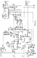
- the engine control system 18 is a microprocessor based system which controls the operation of in the particular example, the fuel system 19 of a six cylinder four stroke compression ignition engine 20.
- the engine has a crankshaft and a camshaft indicated by the dotted lines 21, 22 respectively.
- the processing circuit 23 has an input 10 which is connected to the output of the shaping circuit 24 the input of which is connected to a transducer 25 responsive to the passage of teeth on a wheel 26 mounted on the crankshaft 21.
- the teeth on the wheel 26 are disposed at 6° intervals and at three equi-angularly spaced positions about the axis of rotation of the wheel there are gaps each having the width of two teeth.
- the processing circuit 23 has a further input 11 connected to the output of a further shaping circuit 27 the input of which is connected to a transducer 28 responsive to the passage of teeth on a wheel 29 mounted on the camshaft 22.
- the wheel 29 has six teeth about its periphery corresponding to the number of engine cylinders.
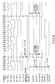
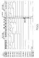
- the shaping circuits 24, 27 associated with the transducers 25, 28 produce from what can be regarded as generally sinusoidal signals produced by the transducers, well defined pulses and at IC21 pin 4 and IC23 pin 2 in Figure 4, can be seen inversions of the pulses produced by the shaping circuits. It will be noted that the cylinder identification pulses derived from the transducer 28 are arranged to occur in the gaps which occur in the series of signals derived from the transducer 25.
- the processing circuit 23 is provided with a first output 12 at which it is intended should appear a series of signals (the so-called N signals) corresponding to the six angularly spaced teeth on the wheel 29 associated with the transducer 28 and at a second output 13, a pulse signal (the so-called (+1) signal) which corresponds to the further tooth provided on said wheel.
- a pulse signal the so-called (+1) signal
- processing circuit has three further outputs 15, 16 and 17 at which during the operation of the circuit so-called artificial N, (+1) and latched (+1) signals respectively appear which can be utilised by the microprocessor of the associated control system 18 in the event of failure of the signal from the second transducer.
- the processing circuit 23 includes a binary counter IC1 the input of which is connected to the output of an inverter IC21 having its input connected to the input terminal 10. Also provided is an 8 input NAND gate IC3 having one of its inputs connected by way of a further inverter IC22 to the input of the counter ICI. A capacitor is connected to the output of the inverter IC22 for the purpose of providing a delay and a further two unused inputs of the NAND gate are connected to a positive source. The remaining inputs of the NAND gate are connected to the stage outputs of the counter IC1 and some of the connections include inverters so that in the particular example, the output of the NAND gate goes negative when the count value of the counter reaches 18.
- the output of the NAND gate IC3 is supplied to one input of an AND gate IC41 the two other inputs of which are normally held positive. As a result when the count value 18 is attained the output of the AND gate IC41 goes negative and this is utilised to trigger a monostable IC6.
- the output of the monostable is connected to the output terminal 15 and provides the artificial N signal.
- the counter IC1 is reset.
- the input terminal 11 is connected by way of an inverter IC23 to one input of a latch IC8 having its preset input connected to the output of the AND gate IC41.
- One output of the latch is connected to one input of an AND gate IC42 the output of which is connected to the output terminal 12 and also to the OR gate IC5.
- the second input of the AND gate is connected to the input terminal 11.
- the engine position pulse (+1) which is supplied to the input 11 is ignored because the latch IC8 is held in its reset state by the inverted previous (N) signal applied to the latch.
- the AND gate IC42 is unable to pass the engine position pulse to the output terminal 12.
- a three input AND gate IC43 is provided and the output of this is connected to terminal 13.
- One of the inputs is connected to the input terminal 11, a second input is connected to a further output of the latch IC8 and the third input is connected to the output of the fourth count stage of the counter IC1.
- both the counter output and the latch output are high when the engine position pulse (+1) is generated and so this appears at the output terminal 13, but low when the cylinder identification pulses (N) are generated so that these do not appear at the output terminal 13.
- a latched (+1) signal is required and this is obtained by providing a latch IC18 having an input connected to the AND gate IC43.
- the latch IC18 can be reset by a signal provided by the microprocessor of the control circuit 18.
- a further counter IC9 is provided together with an associated NAND gate IC11. These correspond to the counter IC1 and the NAND gate IC3 but because the (+1) signal occurs only once per two revolutions of the engine, the count value of the IC9/IC11 combination is set to 107.
- the change in the output of the NAND gate IC11 when the set count value is attained, is utilised by way of NAND gate IC71 and latch IC121 to set one input of a flip-flop IC122 high so that the next two pulses of the inverted input signal from the input terminal 10, can clock the flip-flop to produce an output pulse which is the artificial (+1) signal which is supplied to the output terminal 16.
- This pulse is also utilised to reset the counter IC9 and the latch IC121 is reset by an output from the flip-flop.
- a latched (+1) output can be obtained at output terminal 17 using a further latch IC19 which as with the latch IC18, can be reset by a signal from the microprocessor.
- the (+1) signal at the terminal 13 is supplied by way of an inverter 20 to an input of the NAND gate IC71 to provide for synchronisation of the counter IC9.
- the processing circuit as described is able to provide the required separation of the cylinder identification and engine position signals produced by the transducer 28 associated with the disc or wheel driven by the engine camshaft and considerable savings so far as the software is concerned are effected.
- the transducer 28 should the transducer 28 fail during operation of the engine artificial cylinder identification and engine position signals will be supplied which will enable the engine to continue to run. It will be understood that for an engine having a different number of cylinders, it is only necessary to alter the number to teeth on the wheel 29 and the gaps in the wheel 26 and the count value of the counters.
- the disc or wheel 26 driven by the engine crankshaft 21 has missing teeth this is not essential to the operation of the circuit. If there are no missing teeth all that is necessary is to alter the count values of the IC1/IC3 and IC9/IC11 combinations.
Landscapes
- Engineering & Computer Science (AREA)
- Chemical & Material Sciences (AREA)
- Combustion & Propulsion (AREA)
- Mechanical Engineering (AREA)
- General Engineering & Computer Science (AREA)
- Combined Controls Of Internal Combustion Engines (AREA)
Claims (3)
- Circuit de traitement de signal (23) pour une utilisation avec un système de commande (18) d'un moteur à combustion interne, le circuit de traitement, en utilisation, recevant une première série de signaux provenant d'un premier transducteur (25), les signaux dépendant d'une position de vilebrequin et étant indicatifs de celle-ci, les signaux de la première série survenant selon des intervalles relativement petits de rotation du vilebrequin du moteur, et une seconde série de signaux provenant d'un second transducteur (28) sensible à la rotation de l'arbre de cames ou de vilebrequin (21), les signaux de la seconde série survenant selon des intervalles relativement importants de rotation du vilebrequin de moteur (21) et jouant le rôle de signaux d'identification de cylindre de moteur, les signaux de la seconde série incluant un signal supplémentaire qui survient un intervalle prédéterminé avant l'un des signaux d'identification de cylindre et qui joue le rôle de signal de position de moteur, caractérisé en ce que le circuit de traitement (23) opère pour produire respectivement au niveau de première et seconde bornes de sortie (12, 13), les signaux d'identification de cylindre de moteur et le signal de position de moteur, ceux-ci étant dérivés à partir de la seconde série de signaux, et respectivement au niveau de troisième et quatrième bornes de sortie (15, 16), des signaux d'identification de cylindre de moteur artificiels et un signal de position de moteur, les signaux artificiels étant générés à partir de ladite première série de signaux.
- Circuit de traitement de signal selon la revendication 1, caractérisé en ce qu'il comprend un premier moyen de comptage d'impulsions (IC1, IC3) sensible à la première série de signaux, un premier moyen de porte (IC8, IC42, IC43) pour recevoir la seconde série de signaux, le premier moyen de porte étant commandé par ledit premier moyen de comptage d'impulsions de manière à appliquer les signaux d'identification de cylindre de moteur sur la première borne de sortie (12) et le signal de position de moteur sur la seconde borne de sortie (13), le circuit de traitement incluant un circuit monostable (IC6) commandé par ledit premier moyen de comptage d'impulsions (IC1, IC3) pour produire au niveau de la troisième borne de sortie (15) un signal d'identification de cylindre de moteur artificiel et le circuit de traitement comprenant en outre un second moyen de comptage d'impulsions (IC9, IC11) sensible à la première série de signaux et un second moyen de porte (IC121, IC122) commandé par le second moyen de comptage d'impulsions pour produire un signal de position de moteur artificiel au niveau de la quatrième borne de sortie (17).
- Circuit de traitement de signal selon la revendication 2, caractérisé par un moyen pour initier un fonctionnement du premier moyen de porte (IC8, IC42, IC43) lors d'une tentative pour démarrer le moteur associé en l'absence de ladite seconde série de signaux.
Applications Claiming Priority (2)
| Application Number | Priority Date | Filing Date | Title |
|---|---|---|---|
| GB939309527A GB9309527D0 (en) | 1993-05-08 | 1993-05-08 | Processing circuit |
| GB9309527 | 1993-05-08 |
Publications (2)
| Publication Number | Publication Date |
|---|---|
| EP0624723A1 EP0624723A1 (fr) | 1994-11-17 |
| EP0624723B1 true EP0624723B1 (fr) | 1997-09-10 |
Family
ID=10735173
Family Applications (1)
| Application Number | Title | Priority Date | Filing Date |
|---|---|---|---|
| EP94303017A Expired - Lifetime EP0624723B1 (fr) | 1993-05-08 | 1994-04-26 | Circuit de traitement de signal pour utilisation dans un système de commande de moteur à combustion interne |
Country Status (5)
| Country | Link |
|---|---|
| US (1) | US5499534A (fr) |
| EP (1) | EP0624723B1 (fr) |
| DE (1) | DE69405453T2 (fr) |
| ES (1) | ES2108939T3 (fr) |
| GB (1) | GB9309527D0 (fr) |
Families Citing this family (3)
| Publication number | Priority date | Publication date | Assignee | Title |
|---|---|---|---|---|
| US5860406A (en) * | 1996-04-10 | 1999-01-19 | Caterpillar Inc. | Engine timing apparatus and method of operating same |
| US6932033B2 (en) * | 2003-07-10 | 2005-08-23 | Borgwarner Inc. | System and method for improving VCT closed-loop response at low cam torque frequency |
| US8688351B2 (en) * | 2010-02-26 | 2014-04-01 | Clean Air Power, Inc. | Modification of engine control signal timing by emulation of engine position sensors |
Family Cites Families (14)
| Publication number | Priority date | Publication date | Assignee | Title |
|---|---|---|---|---|
| US4338813A (en) * | 1980-09-02 | 1982-07-13 | Motorola Inc. | Electronic engine synchronization and timing apparatus |
| JPS5749026A (en) * | 1980-09-09 | 1982-03-20 | Nissan Motor Co Ltd | Crank position signal adjusting device |
| JPS5862368A (ja) * | 1981-10-12 | 1983-04-13 | Nec Home Electronics Ltd | エンジン点火制御装置 |
| GB8322886D0 (en) * | 1983-08-25 | 1983-09-28 | Lucas Ind Plc | Transducer means |
| JPS61272471A (ja) * | 1985-05-27 | 1986-12-02 | Honda Motor Co Ltd | 内燃エンジンの基準クランク角度位置検出系異常時の点火時期制御方法 |
| JPH0639947B2 (ja) * | 1986-05-08 | 1994-05-25 | 株式会社日立製作所 | 低圧電子配電点火装置 |
| JPS63154828A (ja) * | 1986-12-19 | 1988-06-28 | Fuji Heavy Ind Ltd | 内燃機関のクランク角度検出装置 |
| JP2527971B2 (ja) * | 1987-07-15 | 1996-08-28 | 株式会社ゼクセル | 内燃機関用制御装置 |
| US5182943A (en) * | 1989-11-24 | 1993-02-02 | Mitsubishi Denki K.K. | Cylinder identification apparatus |
| DE4005123A1 (de) * | 1990-02-17 | 1991-08-22 | Bosch Gmbh Robert | Zuendanlage fuer brennkraftmaschinen |
| US5156125A (en) * | 1990-10-11 | 1992-10-20 | Mitsubishi Denki Kabushiki Kaisha | Engine control apparatus |
| DE4040828C2 (de) * | 1990-12-20 | 2000-05-18 | Bosch Gmbh Robert | Steuersystem für eine Kraftstoffpumpe |
| KR950009972B1 (en) * | 1991-07-04 | 1995-09-04 | Mitsubishi Electric Corp | Cylinder identifying apparatus for a multi-cylinder internal combustion engine |
| JP2790574B2 (ja) * | 1992-06-25 | 1998-08-27 | 三菱電機株式会社 | 内燃機関制御装置 |
-
1993
- 1993-05-08 GB GB939309527A patent/GB9309527D0/en active Pending
-
1994
- 1994-04-26 DE DE69405453T patent/DE69405453T2/de not_active Expired - Fee Related
- 1994-04-26 EP EP94303017A patent/EP0624723B1/fr not_active Expired - Lifetime
- 1994-04-26 ES ES94303017T patent/ES2108939T3/es not_active Expired - Lifetime
- 1994-04-28 US US08/234,826 patent/US5499534A/en not_active Expired - Fee Related
Also Published As
| Publication number | Publication date |
|---|---|
| GB9309527D0 (en) | 1993-06-23 |
| ES2108939T3 (es) | 1998-01-01 |
| DE69405453D1 (de) | 1997-10-16 |
| DE69405453T2 (de) | 1998-02-26 |
| US5499534A (en) | 1996-03-19 |
| EP0624723A1 (fr) | 1994-11-17 |
Similar Documents
| Publication | Publication Date | Title |
|---|---|---|
| US5269274A (en) | Method and device for an open-loop control system for an internal combustion engine | |
| US4941445A (en) | Electronic position sensor assembly and engine control system | |
| EP0130762B1 (fr) | Détecteur de position angulaire | |
| US4553426A (en) | Reference pulse verification circuit adaptable for engine control | |
| JPS6352229B2 (fr) | ||
| US4457286A (en) | Engine ignition system | |
| US4644917A (en) | Method and apparatus for controlling an internal combustion engine | |
| DE10104273B4 (de) | Impulse verschiedener Frequenzen verwendende Kraftmaschinen-Steuereinheit | |
| JP3508720B2 (ja) | エンジン制御装置 | |
| EP0624723B1 (fr) | Circuit de traitement de signal pour utilisation dans un système de commande de moteur à combustion interne | |
| JP3506116B2 (ja) | エンジン制御装置 | |
| US5060614A (en) | Ignition timing control system for an engine having backup function for failure | |
| JP2690315B2 (ja) | 内燃機関に対する点火装置および噴射装置 | |
| EP0244830B1 (fr) | Distributeur électronique du signal d'allumage d'un moteur d'automobile | |
| JPS6325179B2 (fr) | ||
| JPH04219468A (ja) | 内燃機関の点火装置 | |
| US4498444A (en) | Method of controlling engine | |
| US4372273A (en) | Quadrature trigger system for sequential fuel injection | |
| US5575258A (en) | Apparatus and method for determining engine revolution displacement for multi-cylinder four-stroke internal combustion engine | |
| JP3508727B2 (ja) | エンジン制御装置 | |
| JPH0681915B2 (ja) | 内燃機関用逆転防止装置 | |
| US5978436A (en) | Device for electronically simulating the position of a component | |
| JP2792976B2 (ja) | 内燃機関の制御方法及び制御装置 | |
| EP0879956B1 (fr) | Capteur électronique de position associé à système de commande | |
| JPH062603A (ja) | 内燃機関制御装置 |
Legal Events
| Date | Code | Title | Description |
|---|---|---|---|
| PUAI | Public reference made under article 153(3) epc to a published international application that has entered the european phase |
Free format text: ORIGINAL CODE: 0009012 |
|
| AK | Designated contracting states |
Kind code of ref document: A1 Designated state(s): DE ES FR GB IT SE |
|
| 17P | Request for examination filed |
Effective date: 19950419 |
|
| 17Q | First examination report despatched |
Effective date: 19960712 |
|
| GRAG | Despatch of communication of intention to grant |
Free format text: ORIGINAL CODE: EPIDOS AGRA |
|
| GRAH | Despatch of communication of intention to grant a patent |
Free format text: ORIGINAL CODE: EPIDOS IGRA |
|
| RAP1 | Party data changed (applicant data changed or rights of an application transferred) |
Owner name: LUCAS INDUSTRIES PUBLIC LIMITED COMPANY |
|
| GRAH | Despatch of communication of intention to grant a patent |
Free format text: ORIGINAL CODE: EPIDOS IGRA |
|
| GRAA | (expected) grant |
Free format text: ORIGINAL CODE: 0009210 |
|
| AK | Designated contracting states |
Kind code of ref document: B1 Designated state(s): DE ES FR GB IT SE |
|
| ITF | It: translation for a ep patent filed | ||
| REF | Corresponds to: |
Ref document number: 69405453 Country of ref document: DE Date of ref document: 19971016 |
|
| ET | Fr: translation filed | ||
| REG | Reference to a national code |
Ref country code: ES Ref legal event code: FG2A Ref document number: 2108939 Country of ref document: ES Kind code of ref document: T3 |
|
| PGFP | Annual fee paid to national office [announced via postgrant information from national office to epo] |
Ref country code: FR Payment date: 19980409 Year of fee payment: 5 |
|
| PG25 | Lapsed in a contracting state [announced via postgrant information from national office to epo] |
Ref country code: GB Free format text: LAPSE BECAUSE OF NON-PAYMENT OF DUE FEES Effective date: 19980426 |
|
| PG25 | Lapsed in a contracting state [announced via postgrant information from national office to epo] |
Ref country code: SE Free format text: LAPSE BECAUSE OF NON-PAYMENT OF DUE FEES Effective date: 19980427 |
|
| PGFP | Annual fee paid to national office [announced via postgrant information from national office to epo] |
Ref country code: ES Payment date: 19980428 Year of fee payment: 5 |
|
| PLBE | No opposition filed within time limit |
Free format text: ORIGINAL CODE: 0009261 |
|
| STAA | Information on the status of an ep patent application or granted ep patent |
Free format text: STATUS: NO OPPOSITION FILED WITHIN TIME LIMIT |
|
| 26N | No opposition filed | ||
| GBPC | Gb: european patent ceased through non-payment of renewal fee |
Effective date: 19980426 |
|
| EUG | Se: european patent has lapsed |
Ref document number: 94303017.1 |
|
| PG25 | Lapsed in a contracting state [announced via postgrant information from national office to epo] |
Ref country code: DE Free format text: LAPSE BECAUSE OF NON-PAYMENT OF DUE FEES Effective date: 19990202 |
|
| PG25 | Lapsed in a contracting state [announced via postgrant information from national office to epo] |
Ref country code: ES Free format text: LAPSE BECAUSE OF NON-PAYMENT OF DUE FEES Effective date: 19990427 |
|
| PG25 | Lapsed in a contracting state [announced via postgrant information from national office to epo] |
Ref country code: FR Free format text: LAPSE BECAUSE OF NON-PAYMENT OF DUE FEES Effective date: 19991231 |
|
| REG | Reference to a national code |
Ref country code: FR Ref legal event code: ST |
|
| REG | Reference to a national code |
Ref country code: ES Ref legal event code: FD2A Effective date: 20010503 |
|
| PG25 | Lapsed in a contracting state [announced via postgrant information from national office to epo] |
Ref country code: IT Free format text: LAPSE BECAUSE OF NON-PAYMENT OF DUE FEES;WARNING: LAPSES OF ITALIAN PATENTS WITH EFFECTIVE DATE BEFORE 2007 MAY HAVE OCCURRED AT ANY TIME BEFORE 2007. THE CORRECT EFFECTIVE DATE MAY BE DIFFERENT FROM THE ONE RECORDED. Effective date: 20050426 |