EP0624929B1 - Connecteur avec le contact à circuit court - Google Patents
Connecteur avec le contact à circuit court Download PDFInfo
- Publication number
- EP0624929B1 EP0624929B1 EP94107318A EP94107318A EP0624929B1 EP 0624929 B1 EP0624929 B1 EP 0624929B1 EP 94107318 A EP94107318 A EP 94107318A EP 94107318 A EP94107318 A EP 94107318A EP 0624929 B1 EP0624929 B1 EP 0624929B1
- Authority
- EP
- European Patent Office
- Prior art keywords
- connector
- terminals
- pair
- circuit terminal
- short
- Prior art date
- Legal status (The legal status is an assumption and is not a legal conclusion. Google has not performed a legal analysis and makes no representation as to the accuracy of the status listed.)
- Expired - Lifetime
Links
- 239000004020 conductor Substances 0.000 claims description 3
- 230000000063 preceeding effect Effects 0.000 claims 2
- 238000010276 construction Methods 0.000 description 4
- 230000000717 retained effect Effects 0.000 description 3
- 238000003780 insertion Methods 0.000 description 2
- 230000037431 insertion Effects 0.000 description 2
- 238000007689 inspection Methods 0.000 description 2
- 238000009434 installation Methods 0.000 description 2
- 230000008878 coupling Effects 0.000 description 1
- 238000010168 coupling process Methods 0.000 description 1
- 238000005859 coupling reaction Methods 0.000 description 1
- 230000000694 effects Effects 0.000 description 1
- 230000005684 electric field Effects 0.000 description 1
- 230000002708 enhancing effect Effects 0.000 description 1
- 238000012986 modification Methods 0.000 description 1
- 230000004048 modification Effects 0.000 description 1
Images
Classifications
-
- H—ELECTRICITY
- H01—ELECTRIC ELEMENTS
- H01R—ELECTRICALLY-CONDUCTIVE CONNECTIONS; STRUCTURAL ASSOCIATIONS OF A PLURALITY OF MUTUALLY-INSULATED ELECTRICAL CONNECTING ELEMENTS; COUPLING DEVICES; CURRENT COLLECTORS
- H01R13/00—Details of coupling devices of the kinds covered by groups H01R12/70 or H01R24/00 - H01R33/00
- H01R13/66—Structural association with built-in electrical component
- H01R13/70—Structural association with built-in electrical component with built-in switch
- H01R13/703—Structural association with built-in electrical component with built-in switch operated by engagement or disengagement of coupling parts, e.g. dual-continuity coupling part
- H01R13/7031—Shorting, shunting or bussing of different terminals interrupted or effected on engagement of coupling part, e.g. for ESD protection, line continuity
- H01R13/7032—Shorting, shunting or bussing of different terminals interrupted or effected on engagement of coupling part, e.g. for ESD protection, line continuity making use of a separate bridging element directly cooperating with the terminals
Definitions
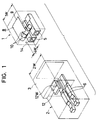
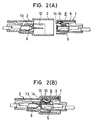
- a pair of terminals connected to e. g. an igniter and a short-circuit terminal of an electrically-conductive material that resiliently contacts the pair of terminals are provided within an air bag-side connector housing, whereas terminals connected to a power source, as well as an insulating plate adapted to intrude between the short-circuit terminal and the pair of terminals (with which the short-circuit terminal is resiliently contacted) when the two connector housings are fitted together are provided within a power source-side connector housing.
Landscapes
- Details Of Connecting Devices For Male And Female Coupling (AREA)
Claims (8)
- Un connecteur comprenant :un premier logement de connecteur (1); etun second logement de connecteur (2),ledit premier logement de connecteur (1) ayant une première paire de terminaux (5) connectables à un dispositif opératif et un terminal court circuit résiliemment précontraint (8) fait d'une matière électro conductrice qui peut être engagé d'une manière pouvant être interrompue avec ladite première paire de terminaux (5), dans lequel ladite première paire de terminaux (5) dans ledit premier logement de connecteur (1) sont disposés dans une position latéralement juxtaposée pour être contactés par des parties de contact (10) respectives dudit terminal court circuit (8),ledit second logement de connecteur (2) pouvant être engagé avec ledit premier logement de connecteur (1) et ayant une seconde paire de terminaux (6) pouvant être engagés avec ladite première paire de terminaux (5) et connectable à une source d'énergie pour ledit dispositif opératif, ledit second logement de connecteur (2) ayant une plaque isolante (12) qui pénètre entre ledit terminal court circuit (8) et ladite paire de premiers terminaux (5) avec laquelle ledit terminal court circuit (8) est résiliemment engagé quand lesdits premier et second logements de connecteur ne sont pas accouplés,caractérisé en ce que
la largeur de ladite plaque isolante (12) est telle qu'elle interrompt le contact électrique entre seulement une desdites pièces de contact (10) et son terminal associé (5) à l'engagement desdits premier (1) et second (2) logements de connecteur. - Le connecteur selon la revendication 1, dans lequel une ouverture (14) est prévue dans ledit premier logement de connecteur (1) pour être en rapport avec ladite plaque d'interruption (12) dans une position connectée desdits logements de connecteur (1, 2), ladite plaque isolante (12) peut être engagée avec ladite ouverture (14) en sorte que dans ladite position connectée desdits logements de connecteur (1, 2) ledit terminal court circuit (8) est rendu non-opératif, et dans une position non-connectée desdits logements de connecteur ledit terminal court circuit (8) est rendu opératif.
- Le connecteur selon la revendication 2, dans lequel ladite ouverture (14) a une largeur d'à peu près la moitié de la largeur dudit premier logement de connecteur (1).
- Le connecteur selon la revendication 1, 2 ou 3, dans lequel la dimension la plus grande de ladite plaque isolante (12) est inférieure à la moitié de la largeur dudit second logement de connecteur (2).
- Le connecteur selon n'importe laquelle des revendications précédentes, dans lequel ledit terminal court circuit (8) comprend une base (9) connectée audit premier logement de connecteur (1), lesdites parties de contact (10) pour engager résiliemment et d'une manière pouvant être interrompue les respectives de ladite première paire de terminaux (5) s'étendant d'un bord de ladite base (9) vers ladite première paire de terminaux (5).
- Le connecteur selon la revendication 5, dans lequel lesdites parties de contact (10) sont comprises de ressorts à lames précontraints vers ladite première paire de terminaux (5).
- Le connecteur selon la revendication 5 ou 6, dans lequel lesdites parties de contact (10) sont faites d'une matière électro conductrice.
- Le connecteur selon n'importe laquelle des revendications précédentes, dans lequel ladite plaque d'interruption (12) a une longeur qui n'est pas plus grande que la moitié de la longueur dudit terminal court circuit (8).
Applications Claiming Priority (2)
| Application Number | Priority Date | Filing Date | Title |
|---|---|---|---|
| JP135365/93 | 1993-05-12 | ||
| JP5135365A JPH06325832A (ja) | 1993-05-12 | 1993-05-12 | コネクタ |
Publications (2)
| Publication Number | Publication Date |
|---|---|
| EP0624929A1 EP0624929A1 (fr) | 1994-11-17 |
| EP0624929B1 true EP0624929B1 (fr) | 1997-08-13 |
Family
ID=15150031
Family Applications (1)
| Application Number | Title | Priority Date | Filing Date |
|---|---|---|---|
| EP94107318A Expired - Lifetime EP0624929B1 (fr) | 1993-05-12 | 1994-05-10 | Connecteur avec le contact à circuit court |
Country Status (4)
| Country | Link |
|---|---|
| US (1) | US5509817A (fr) |
| EP (1) | EP0624929B1 (fr) |
| JP (1) | JPH06325832A (fr) |
| DE (1) | DE69404891T2 (fr) |
Families Citing this family (14)
| Publication number | Priority date | Publication date | Assignee | Title |
|---|---|---|---|---|
| GB9423346D0 (en) * | 1994-11-18 | 1995-01-11 | Amp Great Britain | Electrical interconnection system having retention and shorting features |
| EP0734100B1 (fr) * | 1995-03-20 | 2003-05-07 | The Whitaker Corporation | Connecteur électrique avec une position finale assurée |
| EP0840397B1 (fr) * | 1996-11-04 | 2002-07-31 | Molex Incorporated | Ensemble connecteur électrique avec arrangement court-circuiteur |
| US6186805B1 (en) | 1999-08-31 | 2001-02-13 | Molex Incorporated | Short circuit electrical connector |
| US6315588B1 (en) * | 2000-02-23 | 2001-11-13 | Delphi Technologies, Inc. | Direct insertion shorting clip |
| DE102006019160B4 (de) * | 2006-04-21 | 2008-02-28 | Phoenix Contact Gmbh & Co. Kg | Steckverbinder mit Kurzschlußkontakten |
| DE202006009459U1 (de) * | 2006-06-16 | 2007-10-25 | Weidmüller Interface GmbH & Co. KG | Anschlussleiste mit Kodiervorrichtung |
| JP5203292B2 (ja) * | 2009-05-19 | 2013-06-05 | 株式会社小松製作所 | コネクタおよび建設機械 |
| US8152560B2 (en) * | 2010-04-19 | 2012-04-10 | Tyco Electronics Corporation | Connectivity sensing assembly |
| US8142221B2 (en) | 2010-04-19 | 2012-03-27 | Tyco Electronics Corporation | Plug assembly for a connectivity management system |
| EP2583052B1 (fr) * | 2010-06-18 | 2016-11-16 | Battelle Memorial Institute | Détonateur à base de matériaux non énergétiques |
| JP5272100B1 (ja) * | 2012-07-30 | 2013-08-28 | 株式会社小松製作所 | コネクタおよび建設機械 |
| JP2016207487A (ja) * | 2015-04-23 | 2016-12-08 | 株式会社オートネットワーク技術研究所 | ジョイントコネクタ |
| US10777945B2 (en) | 2019-02-05 | 2020-09-15 | Schweitzer Engineering Laboratories, Inc. | Shorting block for a current transformer |
Family Cites Families (5)
| Publication number | Priority date | Publication date | Assignee | Title |
|---|---|---|---|---|
| US4904196A (en) * | 1987-07-17 | 1990-02-27 | Yazaki Corporation | Releasable connector for electric circuits |
| JPS6477287A (en) * | 1987-09-18 | 1989-03-23 | Hitachi Ltd | Interface circuit for signal transmission equipment |
| US4850888A (en) * | 1988-04-22 | 1989-07-25 | Amp Incorporated | Electrical connector with a deflectable shunt |
| DE8901560U1 (de) * | 1988-11-04 | 1990-03-15 | Grote & Hartmann Gmbh & Co Kg, 5600 Wuppertal | Elektrische Kontakteinrichtung eines Airbags |
| US5131865A (en) * | 1990-02-21 | 1992-07-21 | Yazaki Corporation | Connector apparatus with coupling detecting function |
-
1993
- 1993-05-12 JP JP5135365A patent/JPH06325832A/ja active Pending
-
1994
- 1994-05-10 DE DE69404891T patent/DE69404891T2/de not_active Expired - Fee Related
- 1994-05-10 US US08/240,484 patent/US5509817A/en not_active Expired - Lifetime
- 1994-05-10 EP EP94107318A patent/EP0624929B1/fr not_active Expired - Lifetime
Also Published As
| Publication number | Publication date |
|---|---|
| EP0624929A1 (fr) | 1994-11-17 |
| DE69404891T2 (de) | 1998-01-29 |
| DE69404891D1 (de) | 1997-09-18 |
| US5509817A (en) | 1996-04-23 |
| JPH06325832A (ja) | 1994-11-25 |
Similar Documents
| Publication | Publication Date | Title |
|---|---|---|
| US5516300A (en) | Connector having selectively disabled short circuit terminal | |
| US4978311A (en) | Electrical connector having connector-operable shorting bar | |
| US5647757A (en) | Electrical connector with terminal position assurance | |
| EP0808000B1 (fr) | Structure de connecteur | |
| US5509817A (en) | Connector having short circuit terminal | |
| EP0921600B1 (fr) | Ensemble connecteur d'amorce exempt d'orientation pour ensembles airbag d'automobiles | |
| EP1130692B1 (fr) | Système de connexion électrique | |
| EP0591947B1 (fr) | Système de connexion électrique avec du verrouillage | |
| CN102460851B (zh) | 用于安全约束系统的连接器 | |
| EP0501749B1 (fr) | Dispositif de protection contre les décharges électrostatiques | |
| US4904196A (en) | Releasable connector for electric circuits | |
| US5391087A (en) | Connector | |
| EP0418790B1 (fr) | Mécanisme confirmant le parfait couplage d'un connecteur électrique | |
| US10236640B2 (en) | Electrical connector for a safety restraint system | |
| JPH0458479A (ja) | コネクタ装置 | |
| US5980297A (en) | Lock arm deformation prevention construction | |
| KR200303347Y1 (ko) | 단락 전기 커넥터 | |
| EP0840397B1 (fr) | Ensemble connecteur électrique avec arrangement court-circuiteur | |
| EP0836251A2 (fr) | Connecteur électrique avec shunt | |
| JP2727367B2 (ja) | コネクタ | |
| EP0871253B1 (fr) | Connecteur de détection de verrouillage | |
| US5647762A (en) | Locking structure of short-circuit contact for connectors | |
| JPH03176974A (ja) | 電気コネクタ用短絡装置 | |
| JP3896380B2 (ja) | 電気コネクタ組立体 | |
| JP3884093B2 (ja) | 電気コネクタ組立体 |
Legal Events
| Date | Code | Title | Description |
|---|---|---|---|
| PUAI | Public reference made under article 153(3) epc to a published international application that has entered the european phase |
Free format text: ORIGINAL CODE: 0009012 |
|
| AK | Designated contracting states |
Kind code of ref document: A1 Designated state(s): DE GB |
|
| 17P | Request for examination filed |
Effective date: 19950310 |
|
| 17Q | First examination report despatched |
Effective date: 19951222 |
|
| GRAG | Despatch of communication of intention to grant |
Free format text: ORIGINAL CODE: EPIDOS AGRA |
|
| GRAH | Despatch of communication of intention to grant a patent |
Free format text: ORIGINAL CODE: EPIDOS IGRA |
|
| GRAH | Despatch of communication of intention to grant a patent |
Free format text: ORIGINAL CODE: EPIDOS IGRA |
|
| GRAA | (expected) grant |
Free format text: ORIGINAL CODE: 0009210 |
|
| AK | Designated contracting states |
Kind code of ref document: B1 Designated state(s): DE GB |
|
| REF | Corresponds to: |
Ref document number: 69404891 Country of ref document: DE Date of ref document: 19970918 |
|
| PLBE | No opposition filed within time limit |
Free format text: ORIGINAL CODE: 0009261 |
|
| STAA | Information on the status of an ep patent application or granted ep patent |
Free format text: STATUS: NO OPPOSITION FILED WITHIN TIME LIMIT |
|
| 26N | No opposition filed | ||
| REG | Reference to a national code |
Ref country code: GB Ref legal event code: IF02 |
|
| PGFP | Annual fee paid to national office [announced via postgrant information from national office to epo] |
Ref country code: GB Payment date: 20040505 Year of fee payment: 11 |
|
| PGFP | Annual fee paid to national office [announced via postgrant information from national office to epo] |
Ref country code: DE Payment date: 20040520 Year of fee payment: 11 |
|
| PG25 | Lapsed in a contracting state [announced via postgrant information from national office to epo] |
Ref country code: GB Free format text: LAPSE BECAUSE OF NON-PAYMENT OF DUE FEES Effective date: 20050510 |
|
| PG25 | Lapsed in a contracting state [announced via postgrant information from national office to epo] |
Ref country code: DE Free format text: LAPSE BECAUSE OF NON-PAYMENT OF DUE FEES Effective date: 20051201 |
|
| GBPC | Gb: european patent ceased through non-payment of renewal fee |
Effective date: 20050510 |