EP0625445A1 - Armature de dossier de siège - Google Patents
Armature de dossier de siège Download PDFInfo
- Publication number
- EP0625445A1 EP0625445A1 EP94303508A EP94303508A EP0625445A1 EP 0625445 A1 EP0625445 A1 EP 0625445A1 EP 94303508 A EP94303508 A EP 94303508A EP 94303508 A EP94303508 A EP 94303508A EP 0625445 A1 EP0625445 A1 EP 0625445A1
- Authority
- EP
- European Patent Office
- Prior art keywords
- frame
- seat back
- back frame
- portions
- slit
- Prior art date
- Legal status (The legal status is an assumption and is not a legal conclusion. Google has not performed a legal analysis and makes no representation as to the accuracy of the status listed.)
- Granted
Links
- 238000005452 bending Methods 0.000 claims abstract description 85
- 238000003825 pressing Methods 0.000 claims abstract description 20
- 238000003466 welding Methods 0.000 claims description 55
- 239000011324 bead Substances 0.000 claims description 13
- 238000009751 slip forming Methods 0.000 claims description 9
- 230000001419 dependent effect Effects 0.000 claims 1
- 238000000034 method Methods 0.000 abstract description 30
- 238000010276 construction Methods 0.000 description 25
- XEEYBQQBJWHFJM-UHFFFAOYSA-N Iron Chemical compound [Fe] XEEYBQQBJWHFJM-UHFFFAOYSA-N 0.000 description 8
- 230000004048 modification Effects 0.000 description 7
- 238000012986 modification Methods 0.000 description 7
- 238000011946 reduction process Methods 0.000 description 6
- 230000003247 decreasing effect Effects 0.000 description 4
- 229910052742 iron Inorganic materials 0.000 description 4
- 238000004080 punching Methods 0.000 description 4
- 230000003014 reinforcing effect Effects 0.000 description 4
- 239000006185 dispersion Substances 0.000 description 1
Images








Classifications
-
- B—PERFORMING OPERATIONS; TRANSPORTING
- B60—VEHICLES IN GENERAL
- B60N—SEATS SPECIALLY ADAPTED FOR VEHICLES; VEHICLE PASSENGER ACCOMMODATION NOT OTHERWISE PROVIDED FOR
- B60N2/00—Seats specially adapted for vehicles; Arrangement or mounting of seats in vehicles
- B60N2/68—Seat frames
- B60N2/682—Joining means
Definitions
- the present invention relates to a seat back frame which forms the rear backbone of seats installed in vehicles such as a car, the seat back frame having a frame body in which at least one side frame to support a driver is arranged between an upper frame and a lower frame.
- the present invention relates to a seat back frame in which at least an upper frame part and a pair of side frames can be formed by pressing and bending of a flat frame plate.
- a seat back frame in which a pair of side frames are arranged between an upper frame and a lower frame, both being formed in a frame body, is well-known as shown in Fig. 20.
- Fig. 20 is a perspective view of a conventional seat back frame.
- a seat back frame 100 is essentially constructed from a frame body 101 in which both an upper frame 102 (the frame positioned at upper side in Fig. 20 ) and a lower frame 103 (the frame positioned at lower side in Fig. 20 ) are formed into one body and a pair of side frames 104 each of which is fixed to the left and the right upper frames, respectively.
- the frame body 101 is formed into a predetermined shape, which is substantially square shape and symmetrical at right and left, by bending a hollow pipe at first bending portions 101A, second bending portions 101B and third bending portions 101C.
- the upper frame 102 is constructed from an upper part of the frame body 101 than the third bending parts 101C and the lower frame 103 is constructed from a pair of lower pipes 103 A, 103B which are bent toward inner directions at each of the third bending portions 101C.
- each end portion of the lower pipes 103A, 103B are mutually faced to and fixed by welding.
- the side frames 104 are formed by fixing both ends of a pair of support wires to the upper frame 102 at positions mutually facing therein through welding.
- the side frames 104 are formed to support the driver form both sides of the seat back frame 100.
- a reclining bracket 105 for connecting a reclining device (not shown ) is fixed by welding.
- a hinge plate 106 is fixed by welding, the hinge plate 106 comprising a hinge which is utilized for reclining the seat back frame 100 in cooperation with the reclining device.
- each of the side frames 104 On inner sides of the upper frame 102 on which each of the side frames 104 is arranged, two pairs of spring clamps 108 are fixed by welding, the spring clamps 108 being used for installing S-shaped springs 107 which elastically support a cushion pad (not shown ). And two S-shaped springs 107 are installed between two pairs of the spring clamps 108. Further, one more S-shaped spring 107 is installed between a pair of spring clamps 109 (only one spring clamp 109 is shown in Fig. 20 ), each of the spring clamps 109 being formed with the hinge plate 106 and the reclining bracket 105, respectively.
- a pair of head-rest brackets 110 for installing head-rests are fixed by welding.
- a hollow pipe is bent at the first, the second and the third bending portions 101A, 101B and 101C so that the frame body 101 becomes symmetrical at right and left therein.
- the hollow pipe concludes to be bent at six bending portions.
- end portions of the lower pipes 103A, 103B which are innerly bent are contacted with each other and thereafter fixed by welding. Thereby, the frame body 101 is formed.
- two pairs of spring clamps 108 and a pair of side frames 104 are fixed by spot welding, respectively.
- the reclining bracket 105 is fixed by arc welding at the right lower position of the upper frame 102 and the hinge plate 106 is fixed by welding at the left lower position of the upper frame 102.
- a pair of head-rest brackets 110 are fixed by welding.
- the seat back frame 100 it is necessary to fix each of the members at many positions in the frame body 101 by welding.
- number of welding positions in the frame body 101 is increased it is very difficult to retain precise relations among the members so that each of the members is precisely connected to the frame body 101 with each other.
- the seat back frame 100 is connected to the reclining device there will occur a trouble that rotating operation of the reclining device cannot be smoothly conducted based on connecting error which inevitably occurs among the members.
- a seat for vehicle in Japanese Utility Model Application after substantive examination, laid open No. Hei 3-21,638.
- a pair of side frame plates are fixed at side positions in a seat back frame and zigzag springs are installed between two pairs of spring clamps each of which is arranged on an inner side of the side frame plate, respectively.
- a hinge plate for connecting a reclining device is fixed on one of the side frame plates.
- the side frame plates, the spring clamps and the hinge plate are independently constructed with each other from the seat back frame.
- a frame backbone of the seat back frame is constructed by connecting a pair of side frames, each of which is formed from a flat plate, through spot welding and S-shaped springs are installed between holes to hook thereof, each hole being opened in the side frame.
- each side frame is independently formed and it is necessary to mutually connect each of the side frames by spot welding. Therefore, it cannot be totally obtained enough strength by the above seat back frame and cost thereof cannot be reduced since the side frames have to be connected by spot welding and thus producing cost is increased.
- an upper frame part of the seat back frame which is constructed by connecting each of the side frames is formed in a state of flat plate. Based on this construction, the upper frame part cannot retain enough strength against twisting moment loaded on the seat back frame. As a result, there is a problem that the seat back frame is easily twisted when driver's weight is loaded on the upper right portion or the upper left portion of the seat back frame through his hand(s).
- a first aspect of the invention provides a seat back frame including; a frame body with an upper frame and a lower frame; a pair of side frames each of which is formed between the upper frame and the lower frame, the side frames supporting a driver from both sides of the seat back frame; wherein at least the upper frame and the side frames are formed by bending a frame plate which is obtained from a raw flat plate through pressing treatment; and wherein the upper frame is formed into a pipe form having a slit with edge portions and the slit is welded at several positions of the edge portions.
- a second aspect provides a seat back frame including ; an upper frame; a lower frame; a connecting frame continuously formed from one end of the upper frame; an installing portion for installing a reclining device; a side frame which is formed between the other end of the upper frame and one end of the lower frame, the side frame supporting a driver from one side of the seat back frame; wherein the installing portion, the upper frame, the side frame and the lower frame are formed by bending a frame plate which is obtained from a raw flat plate through pressing treatment; and wherein the other end of the lower frame is welded to the installing portion.
- a third aspect provides a seat back frame including ; a frame body with an upper frame and a lower frame; a pair of side frames each of which is formed between the upper frame and the lower frame, the side frames supporting a driver from both sides of the seat back frame; wherein the upper frame is constructed from a first upper member continuously extended from an upper end of one side frame; a second upper member continuously extended from an upper end of the other side frame; and a third upper member connecting both the first upper member and the second upper member; wherein both the one side frame and the first upper member and both the other side frame and the second upper member are respectively formed by bending a frame plate which is obtained from a raw flat plate through pressing treatment; and wherein the third upper member is welded to both the first upper member and the second upper member.
- the seat back frame is combined with a cushion pad and a seat cover covering the cushion pad, thereby a seat back is formed. And a driver who sits on the seat back is supported through the side frame(s) formed in the frame body between the upper frame and the lower frame from both sides ( one side ) of the seat back.
- both the upper frame and the side frames in the frame body of the seat back frame are formed by bending a frame plate which is obtained from a raw flat plate through pressing treatment and the upper frame is formed into a pipe form having a slit with edge portions and further, the slit is welded at several positions of the edge portions.
- the upper frame and the side frames are independently formed and welded with each other, therefore the upper frame and the side frames can be simultaneously formed into one body from one frame plate.
- the slit of the upper frame is welded at several positions of the edge portions, it can prevent the seat back frame from being seriously deformed since the upper frame can resist against twisting moment occurring due to weight of the driver based on high rigidity thereof, in case that weight is locally loaded on the seat back frame by the driver. And total cost of the seat back frame can be reduced because number of members constructing the seat back frame and number of processes for assembling thereof are decreased.
- the installing portion for installing a reclining device the upper frame, the side frame and the lower frame are formed by bending a frame plate which is obtained from a raw flat plate through pressing treatment and the seat back frame is constructed by welding the lower frame to the installing portion.
- the main members constructing the seat back frame can be simultaneously formed into one body, thus number of the members can be reduced.
- the upper frame of the frame body is constructed from the first upper member, the second upper member and the third upper member. And both one side frame and the first upper member and both the other side frame and the second upper member are respectively formed by bending a frame plate which is obtained from a raw flat plate through pressing treatment. Thereafter, the seat back frame is constructed by welding the third upper member to both the first and the second upper members. Therefore, according to the construction of the third aspect, it can correspond to the seat back frame of a seat back having various widths by dividing the upper frame into three pieces.
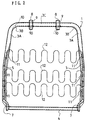
- a seat back frame 1 is basically constructed from a frame body 2 which is shaped in rectangle. And the frame body 2 has an upper frame 3 constructing an upper part of the seat back frame 1, a lower frame 4 constructing a lower part thereof and a pair of side frames 5 each of which is formed between the upper frame 3 and the lower frame 4.
- the upper frame 3 and the side frames 5 are, as mentioned hereinafter, simultaneously formed into one body by bending a first frame plate 20 which is obtained through punching a thin raw metallic plate such as an iron plate into a predetermined shape by pressing treatment.
- the upper frame 3 is formed into a pipe construction having a closed section with a slit 6 and each of the side frames 5 is formed into a flat shape.
- the slit 6 is continuously formed, as shown in Fig.s 1, 3, on central position of an inner side surface in the upper frame 3. Based on this construction, the upper frame 3 can be easily bent through a few bending processes by bending the upper frame 3 according to a predetermined direction. And while bending of the upper frame 3, the upper frame 3 can be precisely bent without twisting thereof.
- the side frames 5 support a driver sitting a seat back from both sides of the seat back frame 1.
- the lower frame 4 is, as mentioned hereinafter, formed into a pipe construction through bending treatment of a second frame plate 21 which is obtained from the raw plate when the first frame plate 20 is taken and further both ends of the lower frame 4 are fixed by welding to installing portions 7 formed at lower ends of the side frames 5 by slightly bending thereof.
- the upper frame 3 has a pair of standing portions 3A each of which is upward extended from each of the side frames 5 as shown in Fig. 1 and a horizontal portion 3C horizontally connecting between both the standing portions 3A through a pair of bending portions 3B. And in the horizontal portion 3A, a pair of concave portions 9 (show in Fig.s 2, 3 ) for fixing a pair of head-rest brackets 8 are formed. On the concave portions 9, the head-rests 8 are fixed by welding. The head-rest brackets 8 are utilized for supporting head-rests ( not shown ). Here, each of the head-rest brackets 8 is, as shown in Fig. 7, is welded at four points on each of the concave portions 9.
- edge portions of the slit 6 in the upper frame 3 are, as shown in Fig. 2, mutually welded and thereby slit connecting portions 10 are formed.
- Each of these slit connecting portions 10 is to give high twisting rigidity to the upper frame 3. Based on the slit connecting portions 10, it can certainly prevent the seat back from being deformed in case that weight of the driver is locally loaded to upper part of the seat back.
- Each of the side frames 5 is continuously formed from each lower end of the standing portions 3A in the upper frame 3 and the side frame 5 is constructed from a flat plate 5A and a wall 5B surrounding the flat plate 5A.
- the wall 5B is formed by gradually opening the slit 6 and surrounding the flat plate 5A.
- a bead 5C for reinforcing the flat plate 5A is formed in the flat plate 5A.
- the wall 5B and the bead 5C formed in the flat plate 5A of the side frame 5 act to give high rigidity to the flat plate 5A.
- three spring clamps 11 are formed by innerly raising the flat plate 5A at three positions.
- Three pairs of S-shaped springs 12 are installed between three pairs of the spring clamps 11.
- a reclining installing portion 13 for installing a reclining device (not shown ) is formed into one body with the side frame 5 and a nut 13B is fixed to a installing hole 13A opened in the reclining installing portion 13. And the reclining device is installed to the installing portion 13 through the installing hole 53A and the nut 13B.
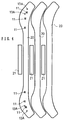
- both the first frame plate 20 which is utilized for forming the upper frame 3 and the side frames 5 and the second frame plate 21 which is utilized for forming the lower frame 4 are simultaneously punched and obtained from the raw flat metallic plate by pressing treatment.
- the second frame plate 21 is obtained from the portion of the raw metallic plate existing between both the first frame plates 20 by effectively using the shape of the first frame plate 20, thereby the raw plate can be efficiently used without wasting thereof.
- portion for forming the side frame 5 in the first frame plate 20 is punched with a size in which bending area for forming the wall 5B in a subsequent process is added.
- three holes shaped like as " ⁇ " are formed in each of the side frame 5 at three positions where the spring clamps 11 are raised and further the installing holes 13A of the reclining installing portions 13 are opened.
- each side frame 5 is reduced by reduction process and thereby, as shown in Fig. 5 (B), the wall 5B is formed around each of the side frame 5.
- walls are formed at side edges of portion which becomes the upper frame 3.
- the installing portion 7 is formed at each end of the side frames 5 by bending both ends ( lower ends ) of the side frames 5.
- the spring clamps 11 are formed by raising process thereof.
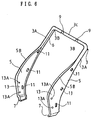
- the walls formed at side edges of the upper frame 3 are round bent into pipe form, thereby the upper frame 3 is formed into the shape with closed section having the slit 6.
- the standing portions 3A and the horizontal portion 3C are formed by bending the upper frame 3 at two bending portions 3B through bending machine and further two concave portions 9, which are utilized for fixing the head-rest brackets 8, are formed at two positions in the horizontal portion 3C.
- the thus constructed state is shown in Fig. 6.
- both ends of the lower frame 4 which is obtained from the second frame plate 21 by rounding thereof into pipe form, are fixed by welding.
- a pair of the head-rest brackets 8 are set to the concave portions 9 in the horizontal portion 3C, as shown in Fig. 3, thereafter each of the brackets 8 is fixed by welding at four positions in each of the concave portions 9.
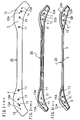
- Fig. 7(A) is a perspective view of the horizontal portion 3C in which the concave portion 9 is enlarged
- Fig. 7(B) is a plan view of the horizontal portion 3C in case of seeing according to a direction shown by an arrow A in Fig. 7(A)
- Fig. 7(C) is a X-X' sectional view of the horizontal portion 3C in case of seeing from X-X' section in Fig. 7(A).
- the concave portion 9 is formed by pressing the horizontal portion 3C from the side direction thereof and two welding portions 9A and 9B are formed at both the upper side and the lower side of the concave portion 9, respectively. And in the welding portions 9A, 9B, a splitting grooves 9C, 9D are formed, respectively and portion existing between the welding portion 9A and 9B is innerly concaved within the horizontal portion 3C.
- the head-rest bracket 8 having a round pipe shape is set to the concave portion 9, the head-rest bracket 8 is contacts with each of the welding portions 9A, 9B at two positions on both sides of each splitting groove 9C, 9D.
- the head-rest bracket 8 is fixed by spot welding onto the concave portion 9 while setting the bracket 8 to the concave portion 9
- the head-rest bracket 8 is fixed onto the concave portion 9 at four positions.
- fixation of both the bracket 8 and the concave portion 9 can be welded for very short time and it can prevent the head-rest bracket 8 from being easily removed since the bracket 8 is welded onto the concave portion 9 at four positions.
- the seat back frame 1 is combined with a cushion pad and a seat cover covering the cushion pad, as a result, a seat back is formed. And when the driver sits on the seat back, the driver is supported from both sides of the seat back frame 1 through a pair of the side frames 5 each of which is formed between the upper frame 3 and the lower frame 4.
- both the upper frame 3 and the side frames 5 in the frame body 2 of the seat back frame 1 are simultaneously formed from the first frame plate 20 obtained from the raw flat metallic plate by bending treatment through bending machine. Therefore, main members to form the seat back frame 1 such as the upper frame 3, the side frames 5, the spring clamps 11 and the reclining installing portions 13 can be simultaneously obtained from one flat first frame plate 20. Thereby, the number of the members and the assembling processes can be reduced, as a result, total cost of the seat back frame 1 can be easily reduced.
- the upper frame 3 is formed into pipe shape with the closed section having the slit 6 and further corresponding to each of the bending portions 3B and each of the concave portions 9, the slit connecting portions 10 are formed by mutually welding the edge portions of the slit 6 in the upper frame 3. Therefore, the upper frame 3 can prevent the seat back from being deformed based on high twisting rigidity given to the upper frame 3 through the slit connecting portions 10, in case that weight of the driver is locally loaded to upper part of the seat back.
- the slit 6 is continuously formed, as shown in Fig.s 1, 3, on central position of an inner side surface in the upper frame 3. Based on this construction, the upper frame 3 can be easily bent through a few bending processes by bending the upper frame 3 according to a predetermined direction. And while bending of the upper frame 3, the upper frame 3 can be precisely bent without twisting thereof.
- each of the head-rest brackets 8 is fixed by spot welding onto the welding portions 9A, 9B in each of the concave portions 9 at four positions, the head-rest brackets 8 can be firmly fixed to the upper frame 3.
- the reclining installing portions 13 connected to the reclining deice are formed into one body with the side frames 5, it is not necessary to weld reclining installing members , which are independently formed and utilized for installing the reclining device, to the seat back frame 1. Therefore, at this point, number of the members and total cost of the seat back frame 1 can be reduced. Further, since the reclining installing portions 13 are obtained by conducting pressing treatment to the first frame plate 20, the portions 13 can be formed with high positional precision, as a result, reclining operation can be smoothly done when the seat back frame 1 is reclined through the reclining device connected to the reclining installing portions 13.
- the wall 5B is formed around the flat plate 5A and the bead 5C is formed on the flat plate 5A. Therefore, it can certainly prevent the flat plate 5A from being transformed when outer force is added to the side frame 5.
- rigidity of the flat side frame 5 can be reinforced based on that the reclining device is connected to the reclining installing portions 13 each of which is formed in each of the side frames 5 of the seat back frame 1.
- a third frame plate 23 from which both the upper frame 3 and the side frames 5 are formed is taken from the raw flat metallic plate.
- pairs of junction plates 24, 25 are respectively formed on both sides corresponding to positions where the bending portions 3B are formed.
- pairs of junction plates 26, 27 are respectively formed on both sides corresponding to positions where the concave portions 9 are formed.
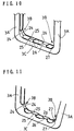
- junction plates 24, 25, 26, 27 are mutually fixed by welding when the upper frame 3 is bent. And portion of the upper frame 3 where the junction plates 24, 25 , 26, 27 do not exist is bent into a shape with a section having substantially " U " shape by opening lower side thereof, as shown in Fig. 10.
- the other construction is as same as in the first embodiment.
- FIG. 10 When the third frame plate 23 is bent similarly to the same method used in the first embodiment, body of the seat back frame 1 ( to which the lower frame 4 is not fixed ) is obtained as shown in Fig. 9. Bending state of the upper frame 3 in the body of the seat back frame 1 is shown in Fig. 10.
- the horizontal portion 3C of the upper frame 3 is formed in the shape with the section having substantially " U " shape by opening lower side ( upper side in Fig. 10 ) thereof.
- the junction plates 24, 25, 26, 27 are innerly bent and mutually fixed by welding, thereby the upper frame 3 is formed into a pipe shape having a closed section at the positions that the junction plates 24, 25, 26, 27 are formed.
- the standing portions 3A are, as shown in Fig.s 9, 10, gradually opened toward the side frames 5.
- junction plates 24, 25, 26, 27 are formed corresponding to the positions where the bending portions 3B and the concave portions 9 are formed in the upper frame 3 and further the thus formed junction plates 24, 25, 26, 27 are mutually bent and welded at the time when bending treatment of the upper frame 3 is conducted, twisting rigidity of the bending portions 3B and the concave portions 9 in the upper frame 3 can be further increased.
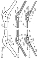
- the upper frame 3 and the side frames 5 are formed from the third frame plate 23, as shown in Fig. 11. That is to say, in Fig. 11, the horizontal portion 3C of the upper frame 3 is formed in the shape with the section having substantially " U " shape by opening lower side ( upper side in Fig. 11 ), similarly to the construction in Fig. 10. And further, corresponding to the positions where the bending portions 3B and the concave portions 9 ( onto which the head-rest brackets 8 are fixed by welding ) are formed in the upper frame 3, the junction plates 24, 25, 26, 27 are innerly bent and mutually fixed by welding, thereby the upper frame 3 is formed into a round pipe shape having a closed section at the positions that the junction plates 24, 25, 26, 27 are formed.
- junction plates 24, 25, 26, 27 are formed corresponding to the positions where the bending portions 3B and the concave portions 9 are formed in the upper frame 3 and further the thus formed junction plates 24, 25, 26, 27 are mutually bent in the round pipe shape and welded at the time when bending treatment of the upper frame 3 is conducted, twisting rigidity of the bending portions 3B and the concave portions 9 in the upper frame 3 can be further increased, similarly to the construction in Fig. 10.
- the seat back frame 1 As shown in Fig. 12. That is to say, in the seat back frame 1 in Fig. 12, a through hole 7A is opened in one of the reclining installing portions 7 ( in Fig. 12, the left portion 7 ). And the right end of the lower frame 4 is welded to the right portion 7. Further, the left end of the lower frame 4 is passed into the through hole 7A and welded to the other portion 7 ( in Fig. 12, the left portion 7 ) after being passed until the length of the lower frame 4 between both the reclining installing portions 7 corresponds to a predetermined width of the seat back frame 1. According to such modification, the length of the lower frame 4 can be finely adjusted in absorbing dispersion occurring in a width direction of the frame 1 when the seat back frame 1 is formed.
- the slit connecting portions 10 are entirely formed at the edge portion of the slit 6 in the upper frame 3.
- a seat back frame according to the second embodiment of the present invention will be described with reference to Fig.s 13 - 15.
- different point from the seat back frame 1 of first embodiment will be mainly described.
- a seat back frame 31 is basically constructed from a frame body 32 which is shaped in rectangle. And the frame body 32 has an upper frame 33 constructing an upper part of the seat back frame 31, a lower frame 34 constructing a lower part thereof and a pair of side frames 35 each of which is formed between the upper frame 33 and the lower frame 34.
- the upper frame 33, the side frames 35 and the lower frame 34 are, as mentioned hereinafter, simultaneously formed into one body by bending a fourth frame plate 44 which is obtained through punching a thin raw metallic plate such as an iron plate into a predetermined shape by pressing treatment.
- the upper frame 33 and the lower frame 34 are formed into a pipe construction having a closed section with a slit 36 and each of the side frames 35 is formed into a flat shape.
- the side frames 35 support a driver sitting a seat back from both sides of the seat back frame 31.
- the lower frame 34 is, as mentioned hereinafter, formed from a pair of lower members 34A, each of which is extended from each of the lower ends of the side frames 35, and both ends of the lower members 34A are mutually welded.
- the upper frame 33 has a pair of standing portions 33A each of which is upward extended from each of the side frames 5 as shown in Fig. 13 and a horizontal portion 33C horizontally connecting between both the standing portions 33A through a pair of bending portions 33B. And in the horizontal portion 33A, a pair of concave portions 39 for fixing a pair of head-rest brackets (not shown ) are formed. On the concave portions 39, the head-rests are fixed by welding. Here, each of the head-rest brackets is welded at four points on each of the concave portions 39, by similar method utilized in the first embodiment as shown in Fig. 7.
- edge portions of the slit 36 in the upper frame 33 are, similarly to the first embodiment, mutually welded and thereby slit connecting portions (not shown ) are formed.
- Each of these slit connecting portions is to give high twisting rigidity to the upper frame 33. Based on the slit connecting portions, it can certainly prevent the seat back from being deformed in case that weight of the driver is locally loaded to upper part of the seat back.
- Each of the side frames 35 is continuously formed from each lower end of the standing portions 33A in the upper frame 33 and the side frame 35 is constructed from a flat plate 35A and a wall 35B surrounding the flat plate 35A.
- the wall 35B is formed by gradually opening the slit 36 and surrounds the flat plate 35A.
- a bead 35C for reinforcing the flat plate 35A is formed in the flat plate 35A.
- the wall 35B and the bead 35C formed in the flat plate 35A of the side frame 35 act to give high rigidity to the flat plate 35A.
- Such action of the wall 35B and the bead 35C is as same as in the first embodiment.
- three spring clamps 41 are formed by innerly raising the flat plate 35A at three positions.
- Three pairs of S-shaped springs (not shown ) are installed between three pairs of the spring clamps 41.
- a reclining installing portion 43 for installing a reclining device (not shown ) is formed into one body with the side frame 35 and a nut is fixed to a installing hole 43A opened in the reclining installing portion 43. And the reclining device is installed to the installing portion 43 through the installing hole 43A and the nut.
- the above construction of the reclining installing portions 43 are as same as in the first embodiment.
- portion for forming the side frame 35 in the fourth frame plate 44 is punched with a size in which bending area for forming the wall 35B in a subsequent process is added. And three holes shaped like as " ⁇ " are formed in each of the side frame 35 at three positions where the spring clamps 41 are raised and further the installing holes 43A of the reclining installing portions 43 are opened. At this point, construction of the fourth frame plate 44 is as same as the first frame plate 20 in the first embodiment.
- portions for forming the lower members 34A which constructs the lower frame 34 in cooperation with each other are extended, therefore the upper frame 33, the side frames 35 and the lower frame 34 are simultaneously formed into one body from the fourth frame plate 44.
- This construction is different from the lower frame 4 in the first embodiment which is independently formed and welded to both of the reclining installing portions 7.
- both the walls formed at side edges of the upper frame 33 and the walls formed at side edges of portions which become the lower frame 34 are round bent into a pipe form, thereby the upper frame 33 and the lower frame 34 are formed into the shape with closed section having the slit 36.
- the standing portions 33A and the horizontal portion 33C are formed by bending the upper frame 33 at two bending portions 33B through bending machine and further two concave portions 39, which are utilized for fixing the head-rest brackets, are formed at two positions in the horizontal portion 33C. Further, each of the lower members 34A extended from the lower ends of the side frames 35 is bent through the bending portions 33D and thereafter both ends of the lower members 34A are mutually fixed by welding.
- the head-rest brackets are welded onto the concave portions 39 in the horizontal portions 33C and further the slit connecting portions are formed corresponding to both the concave portions 39 and the bending portions 33B, methods for welding the head-rest brackets and forming the slit connecting portions are as same as those in the first embodiment, therefore detailed description thereof will be omitted.
- the thus constructed seat back frame 31 is combined with a cushion pad and a seat cover covering the cushion pad, as a result, a seat back is formed.
- a seat back is formed.
- a cushion pad 46 is put on the S-shaped springs installed between three pairs of the spring clamps 41 and the cushion pad 46 is covered by a seat cover 47.
- the lower frame 34 is arranged at lower part of the seat back 45 and the slit 36 formed in the lower frame 34 is opened toward an upper inclined direction as shown in Fig. 15.
- a first hook member 48 is sewed to the inner side of the seat cover 47 near the lower frame 34 and the first hook member 48 has a length corresponding to entire width of the seat back 45.
- a receiving portion 48A having a U-shape in seeing from the side surface thereof is formed.
- a second hook member 49 is sewed to the inner side of the seat cover 47 near the first hook member 48 and the second hook member 49 has a length corresponding to entire width of the seat back 45, the length thereof being as same as that of the first hook member 48.
- a hooking portion 49A which is hooked into the slit 36 is formed into one body with the second hook member 49 and at a side to the first hook member 48 (the right side in Fig. 15 ), a hooking portion 49B which is hooked in the receiving portion 48A of the first hook member 48 is formed into one body with the second hook member 49.
- the seat cover 47 can be easily equipped with the seat back frame 31 in utilizing the slit 36 formed in the lower frame 34.
- the upper frame 33, the side frames 35 and the lower frame 34 can be simultaneously formed from the fourth frame plate 44. Therefore, number of the members to construct the seat back frame 31 and processes for producing thereof can be effectively reduced, thereby total cost of the seat back frame 31 can be decreased.
- the seat cover 47 covering the cushion pad 46 can be certainly and easily equipped with the seat back frame 31 through the receiving portion 48A of the first hook member 48, the hooking portions 49A, 49B of the second hook member 49 in cooperation with the slit 36 formed in the lower member 34.
- a seat back frame according to the third embodiment of the present invention will be described with reference to Fig.s 16 and 17.
- different point from the seat back frame of the first embodiment will be mainly described.
- a seat back frame 51 is basically constructed from a frame body 52 which is shaped in rectangle. And the frame body 52 has an upper frame 53 constructing an upper part of the seat back frame 51, a connecting frame 65 shaped into a round pipe form which is continuously extended from the upper frame 53 at the left side of the seat back frame 51 and has a reclining installing portion 63 for installing a reclining device at the lower end thereof, a lower frame 54 constructing a lower part of the seat back frame 51 and a side frame 55 formed between the upper frame 33 and the lower frame 34 at the right side of the seat back frame 51.
- the reclining installing portion 63, the connecting frame 65, the upper frame 53, the side frame 55 and the lower frame 34 are, as mentioned hereinafter, simultaneously formed into one body by bending a fifth frame plate 64 which is obtained through punching a thin raw metallic plate such as an iron plate into a predetermined shape by pressing treatment.
- the upper frame 53, the lower frame 54 and the connecting frame 65 are formed into a pipe construction having a closed section with a slit 56 and the side frame 55 is formed into a flat shape.
- the side frame 55 supports a driver sitting a seat back from one side of the seat back frame 51.
- the lower frame 54 is, as mentioned hereinafter, extended from the lower end of the side frame 55 and one end ( left end ) thereof is fixed to the reclining installing portion 63 by welding.
- the upper frame 53 has a pair of standing portions 53A, one being upward extended from upper end of the side frame 55 and the other being upward extended from the connecting frame 65, as shown in Fig. 16, and a horizontal portion 53C horizontally connecting between both the standing portions 53A through a pair of bending portions 53B.
- a pair of concave portions 59 for fixing a pair of head-rest brackets are formed.
- the head-rests are fixed by welding.
- each of the head-rest brackets is welded at four points on each of the concave portions 59, by similar method utilized in the first embodiment as shown in Fig. 7.
- edge portions of the slit 56 in the upper frame 53 are, similarly to the first embodiment, mutually welded and thereby slit connecting portions (not shown ) are formed.
- Each of these slit connecting portions are to give high twisting rigidity to the upper frame 53. Based on the slit connecting portions, it can certainly prevent the seat back from being deformed in case that weight of the driver is locally loaded to upper part of the seat back.
- the side frame 55 is continuously formed from lower end of the standing portions 53A in the upper frame 53 and the side frame 55 is constructed from a flat plate 55A and a wall 55B surrounding the flat plate 55A.
- the wall 55B is formed by gradually opening the slit 56 and surrounds the flat plate 55A.
- a bead (not shown ) for reinforcing the flat plate 55A is formed.
- the wall 55B and the bead formed in the flat plate 55A of the side frame 55 act to give high rigidity to the flat plate 55A.
- Such action of the wall 55B and the bead is as same as in the first embodiment.
- three spring clamps 61 are formed by innerly raising the flat plate 65A at three positions. Further, three spring clamps 66 are arranged to the connecting frame 65 corresponding to the spring clamps 61 formed in the side frame 55. Three pairs of S-shaped springs (not shown ) are installed between three pairs of the spring clamps 41, 66.
- the reclining installing portion 63 formed at lower part of the connecting frame 65 an installing hole 63A around which a nut is welded is opened and the reclining device is installed to the installing portion 63 through the installing hole 63A and the nut.
- the above construction of the reclining installing portions 63 is as same as in the first embodiment. Based on such construction of the seat back frame 51 in the third embodiment, it can correspond to a seat back frame where the reclining device is connected to one side of the seat back frame.
- the fifth frame plate 64 which is utilized for forming the reclining installing portion 63, the connecting frame 65, the upper frame 53, the side frame 55 and the lower frame 54 is punched and obtained from the raw flat metallic plate by pressing treatment.
- portion for forming the side frame 55 in the fifth frame plate 64 is punched with a size in which bending area for forming the wall 55B in a subsequent process is added. And three holes shaped like as " ⁇ " are formed in the side frame 55 at three positions where the spring clamps 61 are raised and further the installing hole 63A of the reclining installing portion 63 is opened. At this point, construction of the fifth frame plate 64 is as same as the first frame plate 20 in the first embodiment.
- portion for forming the lower frame 54 is extended into one body. This construction is different from the lower frame 4 in the first embodiment which is independently formed and welded to both of the reclining installing portions 7.
- the walls formed at side edges of the connecting frame 65, the upper frame 53 and the lower frame 54 are round bent into a pipe form, thereby the connecting frame 65, the upper frame 53 and the lower frame 54 are formed into the shape with closed section having the slit 56.
- the standing portions 53A and the horizontal portion 53C are formed by bending the upper frame 53 at two bending portions 53B through bending machine and further two concave portions 59, which are utilized for fixing the head-rest brackets, are formed at two positions in the horizontal portion 53C. Further, portion extended from the lower end of the side frame 55 is bent through the bending portion 53D and thereafter the left end of the lower frame 54 is fixed to the reclining installing portion 63 by welding.
- the head-rest brackets are welded onto the concave portions 59 in the horizontal portions 53C and further the slit connecting portions are formed corresponding to both the concave portions 59 and the bending portions 53B, methods for welding the head-rest brackets and forming the slit connecting portions are as same as those in the first embodiment, therefore detailed description thereof will be omitted.
- the reclining installing portion 63, the connecting frame 65, the upper frame 53, the side frame 55 and the lower frame 54 are simultaneously formed from the fifth frame plate 64 by bending thereof and the seat back frame 51 is completed by welding the end of the lower frame 54 to the reclining installing portion 63. Therefore, number of the members to construct the seat back frame 51 and processes for producing thereof can be effectively reduced and thereby total cost of the seat back frame 51 can be decreased. Further, the seat back frame 51 can correspond to the frame in which the reclining device is connected to one side of the seat back frame.
- a seat back frame 71 is basically constructed from a frame body 72 which is shaped in rectangle. And the frame body 72 has an upper frame 73 constructing an upper part of the seat back frame 71, a lower frame (not shown ) constructing a lower part thereof and a pair of side frames 75 each of which is formed between the upper frame 73 and the lower frame.
- the upper frame 73 is constructed from a first upper member 73A which is extended from upper end in one of the side frames 75 ( in Fig. 18, the left side frame 75 ) and formed to a horizontal portion 73C by bending at a bending portion 73B, a second upper member 73D which is extended from upper end in the other side frame 75 ( in Fig. 18, the right side frame 75 ) and formed to a horizontal portion 73F by bending at a bending portion 73E and a third upper member 73G which is fixed to both ends of the horizontal portions 73C, 73F by welding.
- the third upper member 73G is constructed into a pipe with closed section having a slit 76 and in the third upper member 73G as in the mentioned embodiments, two concave portions 79 for fixing head-rest brackets are formed.
- the head-rest brackets are fixed by welding onto the concave portions 79 at four positions through the same method utilized in the first embodiment.
- both the left side frame 75 and the first upper member 73A and both the right side frame 75 and the second upper member 73D are simultaneously formed into one body by bending a frame plate (not shown ) which is obtained through punching a thin raw metallic plate such as an iron plate into a predetermined shape by pressing treatment.
- the upper frame 73 is formed into a pipe construction having a closed section with a slit 76 and each of the side frames 75 is formed into a flat shape.
- the side frames 75 support a driver sitting a seat back from both sides of the seat back frame 71.
- the lower frame is a pipe as same as that in the first embodiment and both ends thereof are welded to reclining installing portions 77 formed from lower ends of the side frames 75.
- edge portions of the slit 76 in the upper frame 73 and of the slit 76 in the third upper member 73G are, similarly to the first embodiment, mutually welded and thereby slit connecting portions (not shown ) are formed.
- Each of these slit connecting portions is to give high twisting rigidity to the upper frame 73. Based on the slit connecting portions, it can certainly prevent the seat back from being deformed in case that weight of the driver is locally loaded to upper part of the seat back.
- Each of the side frames 75 is continuously formed from each lower end of the first upper member 73A and the second upper member 73D and the side frame 75 is constructed from a flat plate 75A and a wall 75B surrounding the flat plate 75A.
- the wall 75B is formed by gradually opening the slit 76 and surrounds the flat plate 75A.
- a bead (not shown ) for reinforcing the flat plate 75A is formed.
- the wall 75B and the bead formed in the flat plate 75A of the side frame 75 act to give high rigidity to the flat plate 75A.
- Such action of the wall 75B and the bead is as same as in the first embodiment.
- three spring clamps 81 are formed by innerly raising the flat plate 75A at three positions.
- Three pairs of S-shaped springs (not shown ) are installed between three pairs of the spring clamps 81.
- a reclining installing portion 83 for installing a reclining device (not shown ) is formed into one body with the side frame 75 and a nut is fixed to a installing hole 83A opened in the reclining installing portion 83. And the reclining device is installed to the installing portions 83 through the installing holes 83A and the nuts.
- the above construction of the reclining installing portions 83 are as same as in the first embodiment.
- the thus constructed seat back frame 71 is produced through the same method as that utilized in the first and the second embodiments. Therefore, process for producing the seat back frame 71 will be omitted.
- the upper frame 73 in the frame body 72 is constructed from the first upper member 73A, the second upper member 73D and the third upper member 73G. And both the left side frame 75 and the first upper member 73A and both the right side frame 75 and the second upper member 75D are formed by bending the frame plate which is obtained from the raw plate through pressing treatment. Further, the third upper member 73G is welded to both the first and the second upper members 73A, 73D.
- the seat back frame 71 can correspond to seat back frames which have various kinds of widths.
- the lower frame 84 is divided into three lower members of a first lower member 84A which is extended from lower end of the left side frame 75 and formed with a horizontal portion 84C by bending at a bending portion 84B, a second lower member 84D which is extended from lower end of the right side frame 75 and formed with a horizontal portion 84F by bending at a bending portion 84E and a third lower member 84G which is fixed to both ends of the horizontal portions 84C, 84F.
- the third lower member 84G is a pipe with a closed section having a slit.
- the seat back frame 71 can more flexibly correspond to seat back frames which have various kinds of widths. And in addition to that the first upper member 73A and the second upper member 73D can be simultaneously formed into one body with the side frames 75, the first lower member 84 A and the second lower member 84D can be simultaneously formed into one body with the side frames 75, therefore number of the members for constructing the seat back frame 71 can be reduced. As a result, total cost of the seat back frame 71 can be decreased.
Landscapes
- Engineering & Computer Science (AREA)
- Aviation & Aerospace Engineering (AREA)
- Transportation (AREA)
- Mechanical Engineering (AREA)
- Chair Legs, Seat Parts, And Backrests (AREA)
- Seats For Vehicles (AREA)
Applications Claiming Priority (2)
| Application Number | Priority Date | Filing Date | Title |
|---|---|---|---|
| JP13933493 | 1993-05-17 | ||
| JP139334/93 | 1993-05-17 |
Publications (2)
| Publication Number | Publication Date |
|---|---|
| EP0625445A1 true EP0625445A1 (fr) | 1994-11-23 |
| EP0625445B1 EP0625445B1 (fr) | 1998-08-12 |
Family
ID=15242909
Family Applications (1)
| Application Number | Title | Priority Date | Filing Date |
|---|---|---|---|
| EP94303508A Expired - Lifetime EP0625445B1 (fr) | 1993-05-17 | 1994-05-17 | Armature de dossier de siège |
Country Status (4)
| Country | Link |
|---|---|
| US (1) | US5499863A (fr) |
| EP (1) | EP0625445B1 (fr) |
| CN (1) | CN1123461C (fr) |
| DE (1) | DE69412350T2 (fr) |
Cited By (11)
| Publication number | Priority date | Publication date | Assignee | Title |
|---|---|---|---|---|
| GB2296476A (en) * | 1994-12-20 | 1996-07-03 | Ikeda Bussan Co | Vehicular seat with side air-bag vertically mounted in a cutout or groove in the seat side panel |
| EP0751036A1 (fr) * | 1995-06-30 | 1997-01-02 | Cesa Compagnie Europeenne De Sieges Pour Automobiles | Elément de tube métallique et armature pour dossier de siège de véhicule automobile munie de cet élément |
| WO1997009196A3 (fr) * | 1995-09-08 | 1997-05-09 | Euromotive Ges Mbh | Procede de production du bati du dossier d'un siege de vehicule |
| EP0745508A3 (fr) * | 1995-05-10 | 1998-06-17 | Euromotive Gesellschaft m.b.H. | Procédé de fabrication de l'armature d'un dossier d'un siège de véhicule automobile |
| EP0989019A3 (fr) * | 1998-09-22 | 2000-08-16 | VAW aluminium AG | Siège de véhicule et méthode pour sa fabrication |
| FR2790233A1 (fr) * | 1997-12-11 | 2000-09-01 | Tachi S Co | Armature de dossier de siege, notamment pour vehicule automobile |
| DE10047770A1 (de) * | 2000-09-27 | 2002-04-11 | Bayerische Motoren Werke Ag | Rahmenstruktur, insbesondere Lehnenrahmen für einen Fahrzeugstuhl, umfassend wenigstens zwei Seitenholme und einen diese verbindenden oberen Querträger, jeweils aus Hohlprofilen |
| WO2005054005A1 (fr) * | 2003-12-03 | 2005-06-16 | Daimlerchrysler Ag | Cadre de dossier de siege |
| DE19802873B4 (de) * | 1997-01-21 | 2009-12-03 | Suzuki Motor Corp., Hamamatsu-Shi | Rückenlehnenrahmen |
| EP1493618B1 (fr) * | 2003-07-02 | 2014-04-23 | Fico Cables Lda | Structure de siège |
| IT201700043293A1 (it) * | 2017-04-20 | 2018-10-20 | F I S A Srl | Struttura portante di sedili passeggeri per veicoli |
Families Citing this family (37)
| Publication number | Priority date | Publication date | Assignee | Title |
|---|---|---|---|---|
| JPH0928501A (ja) * | 1995-07-14 | 1997-02-04 | Ikeda Bussan Co Ltd | 座席のフレーム構造 |
| US5769499A (en) * | 1996-06-07 | 1998-06-23 | Lear Corporation | Motor vehicle seat |
| AUPO274796A0 (en) * | 1996-10-04 | 1996-10-31 | Henderson's Industries Pty Ltd | Seat backrest frame |
| US5909923A (en) * | 1997-10-24 | 1999-06-08 | Steelcase Inc. | Chair with novel pivot mounts and method of assembly |
| JP4337201B2 (ja) | 1999-12-27 | 2009-09-30 | トヨタ紡織株式会社 | スプリング構造体の取付構造 |
| JP3467568B2 (ja) * | 2000-09-25 | 2003-11-17 | 日本発条株式会社 | 車両用シートバックフレーム |
| JP2003125891A (ja) * | 2001-10-22 | 2003-05-07 | Aisin Seiki Co Ltd | ランバーサポート装置 |
| CA2370811A1 (fr) * | 2002-02-06 | 2003-08-06 | Bill Frenke | Structure de chassis de siege et methode de formage |
| EP1646528B1 (fr) * | 2003-07-21 | 2010-01-06 | Intier Automotive Inc. | Traversins lateraux ajustables |
| JP4560661B2 (ja) * | 2004-03-31 | 2010-10-13 | テイ・エス テック株式会社 | 座面高さの調整可能なリフター機構を備える車両用シート |
| DE102004035454B4 (de) * | 2004-07-22 | 2015-02-26 | Robert Bosch Gmbh | Trägerelement |
| DE202005001773U1 (de) * | 2005-02-03 | 2006-06-14 | Brose Fahrzeugteile Gmbh & Co. Kommanditgesellschaft, Coburg | Lehnenrahmen für Kraftfahrzeugsitze |
| KR20090128569A (ko) * | 2007-04-18 | 2009-12-15 | 존슨 컨트롤스 테크놀러지 컴퍼니 | 테일러 용접된 시트 및 부품들 |
| JP5339774B2 (ja) * | 2008-05-20 | 2013-11-13 | 日本発條株式会社 | 車両用シートバックのフレーム構造及び該構造を有する車両用シートバック |
| CN102046306A (zh) * | 2008-06-03 | 2011-05-04 | 江森自控科技公司 | 座椅框架-拼接管 |
| DE112008004005T5 (de) | 2008-09-23 | 2012-01-26 | Lear Corporation | Sitzanordnung mit einer Buchse |
| US8714654B2 (en) * | 2008-09-30 | 2014-05-06 | Ts Tech Co., Ltd. | Vehicle seat |
| DE102009025780A1 (de) * | 2009-05-08 | 2010-11-11 | Thyssenkrupp Steel Europe Ag | Lehnenrahmen eines Fahrzeugsitzes |
| DE102009036634B4 (de) | 2009-08-07 | 2022-08-18 | Faurecia Autositze Gmbh | Rahmen für eine Lehne eines Fahrzeugsitzes |
| EP2498644A4 (fr) * | 2009-11-12 | 2015-12-09 | Johnson Controls Tech Co | Ensemble d'armature de dossier de siège en une seule pièce et procédé de fabrication de celle-ci |
| EP2536588B8 (fr) * | 2010-02-19 | 2018-05-02 | Adient Luxembourg Holding S.à r.l. | Structure de dossier de siège monobloc et méthode de fabrication |
| DE102010010188B4 (de) * | 2010-03-01 | 2011-11-10 | Keiper Gmbh & Co. Kg | Fahrzeugsitz, insbesondere Kraftfahrzeugsitz |
| JP5578271B2 (ja) * | 2011-03-01 | 2014-08-27 | トヨタ自動車株式会社 | 車両用シート |
| CN103097186B (zh) * | 2011-08-10 | 2015-11-25 | 丰田自动车株式会社 | 车用座椅 |
| JP5831745B2 (ja) * | 2011-09-17 | 2015-12-09 | スズキ株式会社 | シートの表皮材の取り付け構造 |
| JP5818156B2 (ja) * | 2011-11-29 | 2015-11-18 | 株式会社デルタツーリング | シートフレーム構造の製造方法 |
| JP6056531B2 (ja) * | 2013-02-18 | 2017-01-11 | トヨタ紡織株式会社 | 乗物用シートのフレーム構造 |
| JP6169461B2 (ja) * | 2013-09-30 | 2017-07-26 | トヨタ紡織株式会社 | 乗物用シートのシートフレーム |
| JP6614638B2 (ja) * | 2015-05-12 | 2019-12-04 | 株式会社タチエス | シートフレーム |
| JP6493040B2 (ja) | 2015-07-08 | 2019-04-03 | トヨタ紡織株式会社 | 乗物用シート |
| WO2018029899A1 (fr) | 2016-08-09 | 2018-02-15 | テイ・エス テック株式会社 | Armature de siège |
| JP6774026B2 (ja) * | 2016-12-09 | 2020-10-21 | 三菱自動車工業株式会社 | 車両後部座席構造 |
| CN107087916A (zh) * | 2017-07-06 | 2017-08-25 | 姚燕芳 | 人体工学椅子 |
| US10494062B2 (en) | 2017-11-10 | 2019-12-03 | Robert Kohen | Marine seat with safety rollback |
| CN110074589A (zh) * | 2019-05-09 | 2019-08-02 | 敏华家具制造(惠州)有限公司 | 一种可拆卸式沙发靠背组件 |
| NO346566B1 (no) * | 2020-04-28 | 2022-10-10 | H2 Norway As | Sitteanordning med tilbakelent funksjon |
| CN112658439B (zh) * | 2020-12-11 | 2022-06-28 | 苏州龙宇精密机械有限公司 | 航空座椅精密零配件焊接工艺 |
Citations (8)
| Publication number | Priority date | Publication date | Assignee | Title |
|---|---|---|---|---|
| US1684062A (en) * | 1924-12-22 | 1928-09-11 | Ashtabula Bow Socket Company | Back for automobile seats and the like |
| US2371407A (en) * | 1941-10-11 | 1945-03-13 | Universal Wire Spring Co | Tubular frame construction |
| US2720914A (en) * | 1952-12-08 | 1955-10-18 | Briggs Mfg Co | Seat structure for vehicles |
| GB2059818A (en) * | 1979-10-10 | 1981-04-29 | Volpe F | Manufacturing a metal structure for a seat back of a motor vehicle or the like |
| FR2515946A1 (fr) * | 1981-11-11 | 1983-05-13 | Keiper Automobiltechnik Gmbh | Cadre de dossier pour sieges, notamment pour sieges de vehicules automobiles |
| GB2251182A (en) * | 1990-11-26 | 1992-07-01 | Ikeda Bussan Co | Back-rest frame of a seat |
| US5131721A (en) * | 1990-12-28 | 1992-07-21 | Tachi-S Co., Ltd. | Framework of seat back with armrest |
| WO1993016896A1 (fr) * | 1992-02-24 | 1993-09-02 | Itt Industries, Inc. | Structure de siege tres resistant pour vehicule automobile et procede de fabrication |
Family Cites Families (17)
| Publication number | Priority date | Publication date | Assignee | Title |
|---|---|---|---|---|
| US3544164A (en) * | 1967-07-24 | 1970-12-01 | Toyota Motor Co Ltd | Seat frame construction |
| FR2318759A1 (fr) * | 1975-07-22 | 1977-02-18 | Air France | Siege articule destine aux vehicules de transport et plus particulierement aux aeronefs |
| JPS5419935Y2 (fr) * | 1976-06-07 | 1979-07-20 | ||
| DE7830544U1 (de) * | 1978-10-13 | 1979-02-08 | Keiper Automobiltechnik Gmbh & Co Kg, 5630 Remscheid | Gelenkbeschlag fuer sitze, mit verstellbarer rueckenlehne, insbesondere kraftfahrzeugsitze |
| US4536030A (en) * | 1979-08-22 | 1985-08-20 | Nissan Motor Co., Ltd. | Seat with adjustable side support device |
| DE3010662C2 (de) * | 1980-03-20 | 1985-08-29 | Adam Opel AG, 6090 Rüsselsheim | Sicherheitsrückenlehne für Kraftfahrzeugsitze |
| US4364607A (en) * | 1980-07-28 | 1982-12-21 | Gilardini S.P.A. | Seat for vehicles |
| US4619482A (en) * | 1984-05-01 | 1986-10-28 | Noriyasu Itsuki | Reclining device for a vehicle seat |
| JPH0613267B2 (ja) * | 1985-09-18 | 1994-02-23 | 日産自動車株式会社 | 乗物用座席 |
| FR2594760B1 (fr) * | 1986-02-21 | 1989-11-10 | Renault | Armature de siege a modules de construction assembles |
| FR2611827B1 (fr) * | 1987-03-04 | 1989-07-28 | Cousin Cie Ets A & M Freres | Partie de jonction conformee de tube d'armature de siege avec un mecanisme de reglage d'inclinaison du dossier |
| JPH0751630B2 (ja) * | 1989-06-20 | 1995-06-05 | 住友精化株式会社 | 硬化性組成物 |
| JPH0350785A (ja) * | 1989-07-18 | 1991-03-05 | Matsushita Electric Ind Co Ltd | 混成集積回路装置のパターン形成方法 |
| JP3186085B2 (ja) * | 1991-05-27 | 2001-07-11 | アイシン精機株式会社 | シートバツクフレーム |
| DE4224063C2 (de) * | 1991-07-23 | 1996-12-19 | Toyota Motor Co Ltd | Fahrzeugsitz |
| JP3257043B2 (ja) * | 1992-06-22 | 2002-02-18 | アイシン精機株式会社 | シートバック |
| JP2656715B2 (ja) * | 1992-06-29 | 1997-09-24 | アラコ株式会社 | 車両用座席のフレーム一体成形構造 |
-
1994
- 1994-05-03 US US08/237,584 patent/US5499863A/en not_active Expired - Lifetime
- 1994-05-17 EP EP94303508A patent/EP0625445B1/fr not_active Expired - Lifetime
- 1994-05-17 CN CN94105699.6A patent/CN1123461C/zh not_active Expired - Fee Related
- 1994-05-17 DE DE69412350T patent/DE69412350T2/de not_active Expired - Lifetime
Patent Citations (8)
| Publication number | Priority date | Publication date | Assignee | Title |
|---|---|---|---|---|
| US1684062A (en) * | 1924-12-22 | 1928-09-11 | Ashtabula Bow Socket Company | Back for automobile seats and the like |
| US2371407A (en) * | 1941-10-11 | 1945-03-13 | Universal Wire Spring Co | Tubular frame construction |
| US2720914A (en) * | 1952-12-08 | 1955-10-18 | Briggs Mfg Co | Seat structure for vehicles |
| GB2059818A (en) * | 1979-10-10 | 1981-04-29 | Volpe F | Manufacturing a metal structure for a seat back of a motor vehicle or the like |
| FR2515946A1 (fr) * | 1981-11-11 | 1983-05-13 | Keiper Automobiltechnik Gmbh | Cadre de dossier pour sieges, notamment pour sieges de vehicules automobiles |
| GB2251182A (en) * | 1990-11-26 | 1992-07-01 | Ikeda Bussan Co | Back-rest frame of a seat |
| US5131721A (en) * | 1990-12-28 | 1992-07-21 | Tachi-S Co., Ltd. | Framework of seat back with armrest |
| WO1993016896A1 (fr) * | 1992-02-24 | 1993-09-02 | Itt Industries, Inc. | Structure de siege tres resistant pour vehicule automobile et procede de fabrication |
Cited By (14)
| Publication number | Priority date | Publication date | Assignee | Title |
|---|---|---|---|---|
| US5651582A (en) * | 1994-12-20 | 1997-07-29 | Ikeda Bussan Co., Ltd. | Vehicular seat with side air-bag |
| GB2296476A (en) * | 1994-12-20 | 1996-07-03 | Ikeda Bussan Co | Vehicular seat with side air-bag vertically mounted in a cutout or groove in the seat side panel |
| EP0745508A3 (fr) * | 1995-05-10 | 1998-06-17 | Euromotive Gesellschaft m.b.H. | Procédé de fabrication de l'armature d'un dossier d'un siège de véhicule automobile |
| EP0751036A1 (fr) * | 1995-06-30 | 1997-01-02 | Cesa Compagnie Europeenne De Sieges Pour Automobiles | Elément de tube métallique et armature pour dossier de siège de véhicule automobile munie de cet élément |
| FR2736011A1 (fr) * | 1995-06-30 | 1997-01-03 | Cesa | Element de tube metallique, armature pour siege de vehicule automobile munie de cet element, et dossier de siege muni de cette armature |
| WO1997009196A3 (fr) * | 1995-09-08 | 1997-05-09 | Euromotive Ges Mbh | Procede de production du bati du dossier d'un siege de vehicule |
| DE19802873B4 (de) * | 1997-01-21 | 2009-12-03 | Suzuki Motor Corp., Hamamatsu-Shi | Rückenlehnenrahmen |
| FR2790233A1 (fr) * | 1997-12-11 | 2000-09-01 | Tachi S Co | Armature de dossier de siege, notamment pour vehicule automobile |
| EP0989019A3 (fr) * | 1998-09-22 | 2000-08-16 | VAW aluminium AG | Siège de véhicule et méthode pour sa fabrication |
| DE10047770A1 (de) * | 2000-09-27 | 2002-04-11 | Bayerische Motoren Werke Ag | Rahmenstruktur, insbesondere Lehnenrahmen für einen Fahrzeugstuhl, umfassend wenigstens zwei Seitenholme und einen diese verbindenden oberen Querträger, jeweils aus Hohlprofilen |
| EP1493618B1 (fr) * | 2003-07-02 | 2014-04-23 | Fico Cables Lda | Structure de siège |
| WO2005054005A1 (fr) * | 2003-12-03 | 2005-06-16 | Daimlerchrysler Ag | Cadre de dossier de siege |
| IT201700043293A1 (it) * | 2017-04-20 | 2018-10-20 | F I S A Srl | Struttura portante di sedili passeggeri per veicoli |
| EP3461684A1 (fr) * | 2017-04-20 | 2019-04-03 | F.I.S.A - Fabbrica Italiana Sedili Autoferroviari - SRL | Structure portante pour sièges de véhicule |
Also Published As
| Publication number | Publication date |
|---|---|
| DE69412350T2 (de) | 1999-03-25 |
| DE69412350D1 (de) | 1998-09-17 |
| CN1123461C (zh) | 2003-10-08 |
| CN1097970A (zh) | 1995-02-01 |
| EP0625445B1 (fr) | 1998-08-12 |
| US5499863A (en) | 1996-03-19 |
Similar Documents
| Publication | Publication Date | Title |
|---|---|---|
| US5499863A (en) | Seat back frame | |
| JP3594162B2 (ja) | シートバックフレーム | |
| JP7480741B2 (ja) | シート装置 | |
| JP7509075B2 (ja) | シート装置 | |
| CN104780812B (zh) | 交通工具座椅 | |
| CN100532157C (zh) | 汽车用座椅的座椅靠背框架 | |
| US6637824B1 (en) | Arrangement for securing support springs in vehicle seat frame | |
| JP3099638B2 (ja) | シートバックフレーム | |
| US5810446A (en) | Frame structure of seatback | |
| JP2656715B2 (ja) | 車両用座席のフレーム一体成形構造 | |
| GB2218331A (en) | Passenger seat for motor vehicle | |
| JP3766862B2 (ja) | 自動車用シートのバックレストフレーム | |
| JPH06284941A (ja) | 乗り物のシート用、特に自動車のシート用のシートバック | |
| JP2024059200A (ja) | シート及びその組み立て方法 | |
| JP5733936B2 (ja) | 車両用シート | |
| JP3769429B2 (ja) | シート用ばねアセンブリおよびフレーム装置 | |
| JP7780070B2 (ja) | シートフレーム及び車両用シート | |
| JPH071011Y2 (ja) | 車両用シートのシートクツシヨン | |
| JP3434570B2 (ja) | 車両用座席 | |
| JP2747189B2 (ja) | シート用ばね構造体 | |
| JPH07223468A (ja) | 自動車用シートの取付構造 | |
| JP4029377B2 (ja) | 車両用シートバック、及び該シートバックに配設されるインサートワイヤー | |
| JP2595839Y2 (ja) | シート用バネ構造体 | |
| CA2352593C (fr) | Bati de dossier | |
| JP3346714B2 (ja) | 自動車用シートの構造 |
Legal Events
| Date | Code | Title | Description |
|---|---|---|---|
| PUAI | Public reference made under article 153(3) epc to a published international application that has entered the european phase |
Free format text: ORIGINAL CODE: 0009012 |
|
| AK | Designated contracting states |
Kind code of ref document: A1 Designated state(s): DE FR GB |
|
| 17P | Request for examination filed |
Effective date: 19950522 |
|
| 17Q | First examination report despatched |
Effective date: 19970114 |
|
| GRAG | Despatch of communication of intention to grant |
Free format text: ORIGINAL CODE: EPIDOS AGRA |
|
| GRAG | Despatch of communication of intention to grant |
Free format text: ORIGINAL CODE: EPIDOS AGRA |
|
| GRAH | Despatch of communication of intention to grant a patent |
Free format text: ORIGINAL CODE: EPIDOS IGRA |
|
| GRAH | Despatch of communication of intention to grant a patent |
Free format text: ORIGINAL CODE: EPIDOS IGRA |
|
| GRAA | (expected) grant |
Free format text: ORIGINAL CODE: 0009210 |
|
| AK | Designated contracting states |
Kind code of ref document: B1 Designated state(s): DE FR GB |
|
| REF | Corresponds to: |
Ref document number: 69412350 Country of ref document: DE Date of ref document: 19980917 |
|
| ET | Fr: translation filed | ||
| PLBE | No opposition filed within time limit |
Free format text: ORIGINAL CODE: 0009261 |
|
| STAA | Information on the status of an ep patent application or granted ep patent |
Free format text: STATUS: NO OPPOSITION FILED WITHIN TIME LIMIT |
|
| 26N | No opposition filed | ||
| REG | Reference to a national code |
Ref country code: GB Ref legal event code: IF02 |
|
| PGFP | Annual fee paid to national office [announced via postgrant information from national office to epo] |
Ref country code: DE Payment date: 20130515 Year of fee payment: 20 Ref country code: GB Payment date: 20130515 Year of fee payment: 20 |
|
| PGFP | Annual fee paid to national office [announced via postgrant information from national office to epo] |
Ref country code: FR Payment date: 20130531 Year of fee payment: 20 |
|
| REG | Reference to a national code |
Ref country code: DE Ref legal event code: R071 Ref document number: 69412350 Country of ref document: DE |
|
| REG | Reference to a national code |
Ref country code: GB Ref legal event code: PE20 Expiry date: 20140516 |
|
| PG25 | Lapsed in a contracting state [announced via postgrant information from national office to epo] |
Ref country code: GB Free format text: LAPSE BECAUSE OF EXPIRATION OF PROTECTION Effective date: 20140516 |
|
| PG25 | Lapsed in a contracting state [announced via postgrant information from national office to epo] |
Ref country code: DE Free format text: LAPSE BECAUSE OF EXPIRATION OF PROTECTION Effective date: 20140520 |