EP0625744A1 - Fernsteuerungsvorrichtung - Google Patents
Fernsteuerungsvorrichtung Download PDFInfo
- Publication number
- EP0625744A1 EP0625744A1 EP94106072A EP94106072A EP0625744A1 EP 0625744 A1 EP0625744 A1 EP 0625744A1 EP 94106072 A EP94106072 A EP 94106072A EP 94106072 A EP94106072 A EP 94106072A EP 0625744 A1 EP0625744 A1 EP 0625744A1
- Authority
- EP
- European Patent Office
- Prior art keywords
- transmitter
- angular velocity
- control system
- remote control
- display
- Prior art date
- Legal status (The legal status is an assumption and is not a legal conclusion. Google has not performed a legal analysis and makes no representation as to the accuracy of the status listed.)
- Withdrawn
Links
Images

Classifications
-
- G—PHYSICS
- G06—COMPUTING OR CALCULATING; COUNTING
- G06F—ELECTRIC DIGITAL DATA PROCESSING
- G06F3/00—Input arrangements for transferring data to be processed into a form capable of being handled by the computer; Output arrangements for transferring data from processing unit to output unit, e.g. interface arrangements
- G06F3/01—Input arrangements or combined input and output arrangements for interaction between user and computer
- G06F3/048—Interaction techniques based on graphical user interfaces [GUI]
- G06F3/0487—Interaction techniques based on graphical user interfaces [GUI] using specific features provided by the input device, e.g. functions controlled by the rotation of a mouse with dual sensing arrangements, or of the nature of the input device, e.g. tap gestures based on pressure sensed by a digitiser
- G06F3/0489—Interaction techniques based on graphical user interfaces [GUI] using specific features provided by the input device, e.g. functions controlled by the rotation of a mouse with dual sensing arrangements, or of the nature of the input device, e.g. tap gestures based on pressure sensed by a digitiser using dedicated keyboard keys or combinations thereof
- G06F3/04892—Arrangements for controlling cursor position based on codes indicative of cursor displacements from one discrete location to another, e.g. using cursor control keys associated to different directions or using the tab key
Definitions
- the present invention relates to a remote control system, and particularly to a remote control system used for selecting selective items displayed on, for example, a display.
- a control signal sent from a transmitter In a television and the like adopting a remote control system, functions such as ON and OFF of a power switch, a selection of channels, a volume control and so on are controlled by a control signal sent from a transmitter.
- the control signal from the transmitter is sent mainly by pressing an operating button.
- the operating button of the transmitter increases to deteriorate the operability.
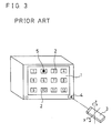
- a system using a three-dimensional mouse for controlling is considered.
- selective items 2 showing the functions are displayed on a display 1 in a matrix.
- movements of the transmitter 3 is utilized.
- two angular velocity sensors are mounted to detect a rotation x about a perpendicular axis and a rotation y about a horizontal axis.
- the control signal corresponding to the rotation is sent to a receiver 4 from the transmitter 3, and the lateral selective items 2 are selected by a cursor 5.
- the control signal corresponding to the rotation is sent to the receiver 4 from the transmitter 3, and the vertical selective items 2 are selected by the cursor 5.
- the cursor 5 moves on the selective items 2 laterally, and when the transmitter 3 is moved vertically, the cursor 5 moves on the selective items 2 vertically.
- any selective items 2 displayed on the display can be selected.
- the selective item 2 by pressing an execution button, the selected function is executed.
- the present invention is directed to a remote control system comprising, a transmitter for transmitting a control signal to control an object being controlled, and a receiver for receiving the control signal from the transmitter, wherein the transmitter is provided with an angular velocity sensor, and an angular velocity about one axis is detected by the angular velocity sensor, and a signal corresponding to the detected angular velocity is transmitted as the control signal.
- the angular velocity about one axis is detected by the angular velocity sensor, and the signal corresponding to the angular velocity is sent to the receiver from the transmitter as the control signal.
- the angular velocity about one axis is detected. That is, the control signal can be sent by rotating the transmitter as turning a door knob without moving it laterally or vertically.
- the transmitter is not necessary to be moved in a large way, and hence the control signal hardly deviates from the receiving range of the receiver.
- a hand is usually unstable laterally or vertically, but is stable in the rotating direction. Therefore, if a cursor is once adjusted to a selective item displayed on a display and the like, there is a little possibility that the selective item changes due to the unstable hand.
- Fig. 1 is an illustrative view showing a television using a remote control system of the present invention.
- Fig. 2 is an illustrative view showing a modified example of selective items displayed on a television shown in Fig. 1.
- Fig. 3 is an illustrative view showing a television using a conventional remote control system using a 3-dimensional mouse as a background of the present invention.
- a remote control system of the present invention is described with reference to a television shown in Fig. 1 as an example.
- the television 10 includes a frame 12 in which a display 14 is mounted.
- a power switch 16 is provided on the television 10, and an electric power is supplied by turning ON the switch 16.
- the television 10 includes a receiver 18 which receives a control signal from a transmitter to be described later. By the control signal from the transmitter, respective functions of the television 10 are selected.
- the transmitter 20 is used for controlling the television 10.
- a main switch 22, a menu switch 24, an execution switch 26 and so on are mounted on the transmitter 20.
- the control signal by infrared rays is transmitted.
- the transmitter 20 is formed into, for example, a rectangular parallelepiped shape, and provided with an angular velocity sensor 27 for detecting an angular velocity z about its longitudinal axis.
- the angular velocity sensors such as a vibration gyroscope utilizing vibration of a vibrating body, a gas-rate sensor, an optical fiber, a rotating gyroscope and so on can be used.
- the control signal is transmitted from a transmitting portion 28 at one longitudinal end of the transmitter 20.
- the television 10 is turned on.
- the menu switch 24 is pressed.
- a plurality of selective items 30 are displayed on the display.
- the selective items 30 are displayed in a circular ring shape, and a cursor 32 is overlapped on one of the selective items 30.
- the transmitting portion 28 of the transmitter 20 is directed toward the receiver 18 and rotated about a longitudinal axis of the transmitter 20. Thereby, the angular velocity is given to the transmitter 20 and is detected by the angular velocity sensor 27. In the angular velocity sensor 27, a direction of rotation and a value of angular velocity are detected, and a corresponding signal is modulated into a pulse signal. The resulting pulse signal is transmitted from the transmitting portion 28 of the transmitter 20 as the control signal.
- a moving direction of the cursor 32 on the display 14 can be changed. That is, when the transmitter 20 is rotated clockwise, the cursor 32 is also moved clockwise on the selective items 30 arranged circularly. When the transmitter 20 is rotated counter clockwise, the cursor 32 is also moved counter clockwise on the selective items 30. When the cursor 32 is adjusted on the desired selective item 30, the cursor 32 is brought to a standstill by stopping the rotation of the transmitter 20. Meanwhile, the selected function is executed by pressing the execution switch 26 in that state.
- the transmitter 20 when selecting the selective items 30, the transmitter 20 is not necessary to be moved laterally or vertically, and there is a little change that the control signal deviates from the receiving range of the receiver 18. Since a hand is mainly unstable vertically and laterally but is stable in the rotating direction, the movement of the cursor 32 due to the unstable hand is lessened and malfunctions can be prevented. Since the operating buttons for selecting the selective items 30 are few and can be selected by the rotating operation, as compared with a button-type transmitter or a 3-dimensional mouse moving vertically and laterally, a good operability is obtained. Since the angular velocity about one axis is to be detected, one angular velocity sensor is sufficient, thus the transmitter 20 can be miniaturized as compared with the 3-dimensional mouse. Furthermore, since only one angular velocity sensor is used, as compared with the conventional 3-dimensional mouse and the like, an electric power consumption is saved and can be utilized at low cost.
- the selective items 30 are arranged circularly in the embodiment shown in Fig. 1, they may be arranged in a square along the display 14 as shown in Fig. 2, any arrangements of the selective items 30 are possible. As such, when the selective items 30 are arranged in a ring shape, the rotation of the transmitter 20 corresponds with the movement of the cursor 32, results in an easy operation. However, the selective items 30 may also be arranged in a matrix as shown in Fig. 3. It is also possible to adopt a moving method, whereby the transmitter 20 is rotated to move the cursor 32, for example, rightward on the selective items 30, and when reaching the right end, shifting to the selective items 30 arranged in the next row. That is, as far as the method is capable of detecting the angular velocity of the transmitter 20 to obtain the corresponding signal as the control signal, any arrangements of the selective items 30 are possible.
- the operating buttons can also be decreased to one by combining the functions.
- this remote control system can be used for controlling all sorts of equipments. For example, by combining a computer on the receiving side and selecting the selective items displayed on the display, it is possible to select programs inputted to the computer. When it is so designed that the signal is sent from the computer to control the other equipment, it is applicable for controlling all sorts of industrial machines. It is not always necessary to use the display for displaying the selective items, for example, LED and the like may also be used for displaying. In such case, the selective item is selected by rotating the transmitter, and the LED which is lit in response thereto may be moved successively. As such, any methods may be used for displaying the selective items.
Landscapes
- Engineering & Computer Science (AREA)
- General Engineering & Computer Science (AREA)
- Theoretical Computer Science (AREA)
- Human Computer Interaction (AREA)
- Physics & Mathematics (AREA)
- General Physics & Mathematics (AREA)
- Selective Calling Equipment (AREA)
- Details Of Television Systems (AREA)
- Position Input By Displaying (AREA)
Applications Claiming Priority (2)
| Application Number | Priority Date | Filing Date | Title |
|---|---|---|---|
| JP5118989A JPH06311564A (ja) | 1993-04-21 | 1993-04-21 | リモートコントロール方式 |
| JP118989/93 | 1993-04-21 |
Publications (1)
| Publication Number | Publication Date |
|---|---|
| EP0625744A1 true EP0625744A1 (de) | 1994-11-23 |
Family
ID=14750257
Family Applications (1)
| Application Number | Title | Priority Date | Filing Date |
|---|---|---|---|
| EP94106072A Withdrawn EP0625744A1 (de) | 1993-04-21 | 1994-04-19 | Fernsteuerungsvorrichtung |
Country Status (2)
| Country | Link |
|---|---|
| EP (1) | EP0625744A1 (de) |
| JP (1) | JPH06311564A (de) |
Cited By (6)
| Publication number | Priority date | Publication date | Assignee | Title |
|---|---|---|---|---|
| EP0773494A1 (de) * | 1995-11-13 | 1997-05-14 | Motorola, Inc. | Bewegungsempfindlicher Cursor zur Bewegungssteuerung in einer Vorrichtung mit virtuellen Bildern |
| EP2075042A3 (de) * | 2005-09-01 | 2009-07-08 | Nintendo Co., Ltd. | Informationsverarbeitungssystem und Programm |
| US8330716B2 (en) | 2008-12-18 | 2012-12-11 | Seiko Epson Corporation | Input device and data processing system |
| US8400474B2 (en) | 2008-12-27 | 2013-03-19 | Funai Electric Co., Ltd. | Imaging apparatus and method of controlling imaging apparatus |
| US8614670B2 (en) | 2008-12-18 | 2013-12-24 | Seiko Epson Corporation | Input device and data processing system |
| US8708822B2 (en) | 2005-09-01 | 2014-04-29 | Nintendo Co., Ltd. | Information processing system and program |
Families Citing this family (4)
| Publication number | Priority date | Publication date | Assignee | Title |
|---|---|---|---|---|
| JP3745182B2 (ja) * | 2000-02-08 | 2006-02-15 | 株式会社Access | 指示方向信号処理方法および装置 |
| JP4803951B2 (ja) * | 2003-05-26 | 2011-10-26 | ソニー株式会社 | 文字入力装置およびその処理方法、記録媒体、並びにプログラム |
| JP4983210B2 (ja) * | 2006-11-10 | 2012-07-25 | セイコーエプソン株式会社 | 表示項目選択システム、操作デバイス、及び、表示項目選択方法 |
| JP5841958B2 (ja) * | 2013-02-22 | 2016-01-13 | セイコーエプソン株式会社 | データ処理システム |
Citations (4)
| Publication number | Priority date | Publication date | Assignee | Title |
|---|---|---|---|---|
| JPS6224777A (ja) * | 1985-07-25 | 1987-02-02 | Matsushita Electric Ind Co Ltd | リモコン制御装置 |
| JPH04292082A (ja) * | 1991-03-20 | 1992-10-16 | Sony Corp | 表示装置 |
| JPH04334197A (ja) * | 1991-05-09 | 1992-11-20 | Mitsubishi Electric Corp | リモートコントロール装置 |
| EP0516862A1 (de) * | 1990-12-19 | 1992-12-09 | Kabushiki Kaisha Yaskawa Denki | Vorrichtung zur multidimensionalen informationseingabe |
-
1993
- 1993-04-21 JP JP5118989A patent/JPH06311564A/ja active Pending
-
1994
- 1994-04-19 EP EP94106072A patent/EP0625744A1/de not_active Withdrawn
Patent Citations (4)
| Publication number | Priority date | Publication date | Assignee | Title |
|---|---|---|---|---|
| JPS6224777A (ja) * | 1985-07-25 | 1987-02-02 | Matsushita Electric Ind Co Ltd | リモコン制御装置 |
| EP0516862A1 (de) * | 1990-12-19 | 1992-12-09 | Kabushiki Kaisha Yaskawa Denki | Vorrichtung zur multidimensionalen informationseingabe |
| JPH04292082A (ja) * | 1991-03-20 | 1992-10-16 | Sony Corp | 表示装置 |
| JPH04334197A (ja) * | 1991-05-09 | 1992-11-20 | Mitsubishi Electric Corp | リモートコントロール装置 |
Non-Patent Citations (4)
| Title |
|---|
| "Continous Discrete Entry", IBM TECHNICAL DISCLOSURE BULLETIN, vol. 36, no. 10, October 1993 (1993-10-01), NEW YORK US, pages 479, XP000412453 * |
| PATENT ABSTRACTS OF JAPAN vol. 11, no. 198 (E - 519) 25 June 1987 (1987-06-25) * |
| PATENT ABSTRACTS OF JAPAN vol. 17, no. 104 (E - 1328) 3 March 1993 (1993-03-03) * |
| PATENT ABSTRACTS OF JAPAN vol. 17, no. 183 (E - 1348) 9 April 1993 (1993-04-09) * |
Cited By (7)
| Publication number | Priority date | Publication date | Assignee | Title |
|---|---|---|---|---|
| EP0773494A1 (de) * | 1995-11-13 | 1997-05-14 | Motorola, Inc. | Bewegungsempfindlicher Cursor zur Bewegungssteuerung in einer Vorrichtung mit virtuellen Bildern |
| EP2075042A3 (de) * | 2005-09-01 | 2009-07-08 | Nintendo Co., Ltd. | Informationsverarbeitungssystem und Programm |
| EP2078547A1 (de) * | 2005-09-01 | 2009-07-15 | Nintendo Co., Ltd. | Informationsverarbeitungssystem und Programm |
| US8708822B2 (en) | 2005-09-01 | 2014-04-29 | Nintendo Co., Ltd. | Information processing system and program |
| US8330716B2 (en) | 2008-12-18 | 2012-12-11 | Seiko Epson Corporation | Input device and data processing system |
| US8614670B2 (en) | 2008-12-18 | 2013-12-24 | Seiko Epson Corporation | Input device and data processing system |
| US8400474B2 (en) | 2008-12-27 | 2013-03-19 | Funai Electric Co., Ltd. | Imaging apparatus and method of controlling imaging apparatus |
Also Published As
| Publication number | Publication date |
|---|---|
| JPH06311564A (ja) | 1994-11-04 |
Similar Documents
| Publication | Publication Date | Title |
|---|---|---|
| US5381080A (en) | Control device | |
| EP0457541A1 (de) | Steuergeräte | |
| EP0625744A1 (de) | Fernsteuerungsvorrichtung | |
| JPS63223913A (ja) | リモートコントロール装置 | |
| EP1336291A2 (de) | Menüsteuerungssystem | |
| CA2043339A1 (en) | Remote control system for controlling a television receiver | |
| US12020887B2 (en) | System and methods for providing orientation compensation in pointing devices | |
| EP0451872B2 (de) | Fernsteuersystem | |
| CA2916860A1 (en) | Grid system and method for remote control | |
| US20090185080A1 (en) | Controlling an electronic device by changing an angular orientation of a remote wireless-controller | |
| CN102376158A (zh) | 多操作面方形遥控器 | |
| KR100833225B1 (ko) | 움직임 인식을 기반으로 하는 리모트 컨트롤 장치 및 방법 | |
| JP4064255B2 (ja) | リモコン信号送信装置 | |
| US6198482B1 (en) | System controller for analyzer | |
| JPH10124246A (ja) | 表示制御装置 | |
| KR100652928B1 (ko) | 제어대상 지시 결정 시스템, 원격지시제어장치, 전자기기및 수신장치 | |
| US20060250355A1 (en) | Image control system | |
| JP2641638B2 (ja) | リモートコントロール装置 | |
| JP2008042748A (ja) | リモコン装置、音響映像装置および遠隔操作方法 | |
| KR102634743B1 (ko) | 포인터 기능을 갖는 리모컨 및 이를 포함한 포인팅 시스템 | |
| JPH06168070A (ja) | 遠隔操作装置 | |
| JPH02201523A (ja) | リモコンシステム | |
| KR100402333B1 (ko) | 디스플레이와 볼 스위치를 갖는 리모트 컨트롤 장치 | |
| KR100699670B1 (ko) | 원격 입력장치를 이용하는 디스플레이 시스템 | |
| KR20130070477A (ko) | 원격제어장치 및 이의 동작 방법 |
Legal Events
| Date | Code | Title | Description |
|---|---|---|---|
| PUAI | Public reference made under article 153(3) epc to a published international application that has entered the european phase |
Free format text: ORIGINAL CODE: 0009012 |
|
| AK | Designated contracting states |
Kind code of ref document: A1 Designated state(s): DE FR GB IT SE |
|
| 17P | Request for examination filed |
Effective date: 19950126 |
|
| 17Q | First examination report despatched |
Effective date: 19990111 |
|
| STAA | Information on the status of an ep patent application or granted ep patent |
Free format text: STATUS: THE APPLICATION HAS BEEN WITHDRAWN |
|
| 18W | Application withdrawn |
Withdrawal date: 19990310 |