EP0626251A1 - Machine d'application de rubans et procédé d'application de rubans plastiques - Google Patents
Machine d'application de rubans et procédé d'application de rubans plastiques Download PDFInfo
- Publication number
- EP0626251A1 EP0626251A1 EP94107987A EP94107987A EP0626251A1 EP 0626251 A1 EP0626251 A1 EP 0626251A1 EP 94107987 A EP94107987 A EP 94107987A EP 94107987 A EP94107987 A EP 94107987A EP 0626251 A1 EP0626251 A1 EP 0626251A1
- Authority
- EP
- European Patent Office
- Prior art keywords
- presser
- tape
- movement
- work surface
- elements
- Prior art date
- Legal status (The legal status is an assumption and is not a legal conclusion. Google has not performed a legal analysis and makes no representation as to the accuracy of the status listed.)
- Withdrawn
Links
- 239000004033 plastic Substances 0.000 title claims abstract description 33
- 238000000034 method Methods 0.000 title claims description 5
- 230000033001 locomotion Effects 0.000 claims abstract description 71
- 230000007704 transition Effects 0.000 claims abstract description 3
- 239000012528 membrane Substances 0.000 claims description 13
- 239000012530 fluid Substances 0.000 claims description 12
- 230000004044 response Effects 0.000 claims description 4
- 230000006872 improvement Effects 0.000 abstract description 5
- 239000002990 reinforced plastic Substances 0.000 abstract description 2
- 239000002131 composite material Substances 0.000 description 8
- 238000005056 compaction Methods 0.000 description 4
- 229920001169 thermoplastic Polymers 0.000 description 3
- OKTJSMMVPCPJKN-UHFFFAOYSA-N Carbon Chemical compound [C] OKTJSMMVPCPJKN-UHFFFAOYSA-N 0.000 description 2
- 229910052799 carbon Inorganic materials 0.000 description 2
- 238000004590 computer program Methods 0.000 description 2
- 239000011521 glass Substances 0.000 description 2
- 239000000463 material Substances 0.000 description 2
- 230000002787 reinforcement Effects 0.000 description 2
- 229920001187 thermosetting polymer Polymers 0.000 description 2
- 239000004416 thermosoftening plastic Substances 0.000 description 2
- 239000004593 Epoxy Substances 0.000 description 1
- 239000004677 Nylon Substances 0.000 description 1
- 230000008901 benefit Effects 0.000 description 1
- 230000008878 coupling Effects 0.000 description 1
- 238000010168 coupling process Methods 0.000 description 1
- 238000005859 coupling reaction Methods 0.000 description 1
- 238000005520 cutting process Methods 0.000 description 1
- 238000010586 diagram Methods 0.000 description 1
- 239000000835 fiber Substances 0.000 description 1
- 230000004886 head movement Effects 0.000 description 1
- 238000010438 heat treatment Methods 0.000 description 1
- 230000002401 inhibitory effect Effects 0.000 description 1
- 230000000977 initiatory effect Effects 0.000 description 1
- 238000005304 joining Methods 0.000 description 1
- 235000015250 liver sausages Nutrition 0.000 description 1
- 238000004519 manufacturing process Methods 0.000 description 1
- 229920001778 nylon Polymers 0.000 description 1
- 229920000098 polyolefin Polymers 0.000 description 1
- 238000003825 pressing Methods 0.000 description 1
- 230000008569 process Effects 0.000 description 1
- 230000000284 resting effect Effects 0.000 description 1
- 238000003860 storage Methods 0.000 description 1
Images



Classifications
-
- B—PERFORMING OPERATIONS; TRANSPORTING
- B29—WORKING OF PLASTICS; WORKING OF SUBSTANCES IN A PLASTIC STATE IN GENERAL
- B29C—SHAPING OR JOINING OF PLASTICS; SHAPING OF MATERIAL IN A PLASTIC STATE, NOT OTHERWISE PROVIDED FOR; AFTER-TREATMENT OF THE SHAPED PRODUCTS, e.g. REPAIRING
- B29C70/00—Shaping composites, i.e. plastics material comprising reinforcements, fillers or preformed parts, e.g. inserts
- B29C70/04—Shaping composites, i.e. plastics material comprising reinforcements, fillers or preformed parts, e.g. inserts comprising reinforcements only, e.g. self-reinforcing plastics
- B29C70/28—Shaping operations therefor
- B29C70/30—Shaping by lay-up, i.e. applying fibres, tape or broadsheet on a mould, former or core; Shaping by spray-up, i.e. spraying of fibres on a mould, former or core
- B29C70/38—Automated lay-up, e.g. using robots, laying filaments according to predetermined patterns
- B29C70/386—Automated tape laying [ATL]
- B29C70/388—Tape placement heads, e.g. component parts, details or accessories
-
- B—PERFORMING OPERATIONS; TRANSPORTING
- B65—CONVEYING; PACKING; STORING; HANDLING THIN OR FILAMENTARY MATERIAL
- B65H—HANDLING THIN OR FILAMENTARY MATERIAL, e.g. SHEETS, WEBS, CABLES
- B65H35/00—Delivering articles from cutting or line-perforating machines; Article or web delivery apparatus incorporating cutting or line-perforating devices, e.g. adhesive tape dispensers
- B65H35/0006—Article or web delivery apparatus incorporating cutting or line-perforating devices
- B65H35/0073—Details
-
- B—PERFORMING OPERATIONS; TRANSPORTING
- B29—WORKING OF PLASTICS; WORKING OF SUBSTANCES IN A PLASTIC STATE IN GENERAL
- B29C—SHAPING OR JOINING OF PLASTICS; SHAPING OF MATERIAL IN A PLASTIC STATE, NOT OTHERWISE PROVIDED FOR; AFTER-TREATMENT OF THE SHAPED PRODUCTS, e.g. REPAIRING
- B29C70/00—Shaping composites, i.e. plastics material comprising reinforcements, fillers or preformed parts, e.g. inserts
- B29C70/04—Shaping composites, i.e. plastics material comprising reinforcements, fillers or preformed parts, e.g. inserts comprising reinforcements only, e.g. self-reinforcing plastics
- B29C70/28—Shaping operations therefor
- B29C70/54—Component parts, details or accessories; Auxiliary operations, e.g. feeding or storage of prepregs or SMC after impregnation or during ageing
- B29C70/545—Perforating, cutting or machining during or after moulding
-
- Y—GENERAL TAGGING OF NEW TECHNOLOGICAL DEVELOPMENTS; GENERAL TAGGING OF CROSS-SECTIONAL TECHNOLOGIES SPANNING OVER SEVERAL SECTIONS OF THE IPC; TECHNICAL SUBJECTS COVERED BY FORMER USPC CROSS-REFERENCE ART COLLECTIONS [XRACs] AND DIGESTS
- Y10—TECHNICAL SUBJECTS COVERED BY FORMER USPC
- Y10T—TECHNICAL SUBJECTS COVERED BY FORMER US CLASSIFICATION
- Y10T156/00—Adhesive bonding and miscellaneous chemical manufacture
- Y10T156/12—Surface bonding means and/or assembly means with cutting, punching, piercing, severing or tearing
- Y10T156/1348—Work traversing type
-
- Y—GENERAL TAGGING OF NEW TECHNOLOGICAL DEVELOPMENTS; GENERAL TAGGING OF CROSS-SECTIONAL TECHNOLOGIES SPANNING OVER SEVERAL SECTIONS OF THE IPC; TECHNICAL SUBJECTS COVERED BY FORMER USPC CROSS-REFERENCE ART COLLECTIONS [XRACs] AND DIGESTS
- Y10—TECHNICAL SUBJECTS COVERED BY FORMER USPC
- Y10T—TECHNICAL SUBJECTS COVERED BY FORMER US CLASSIFICATION
- Y10T156/00—Adhesive bonding and miscellaneous chemical manufacture
- Y10T156/17—Surface bonding means and/or assemblymeans with work feeding or handling means
- Y10T156/1788—Work traversing type and/or means applying work to wall or static structure
Definitions
- This invention relates generally to machines for laying plastic tape, particularly fibre reinforced composite plastic tape, to create reinforced composite plastic structures.
- Such machines generally employ a presser assembly, such as a roller or skidding shoe, to apply and compress laminar plys of the plastic tape onto a work surface, particularly a contoured work surface.
- Tape laying machines are well known in the art for making various composite plastic structures including components for aircraft, components for automobiles and part for ships. These machines have a tape laying head, usually oriented around a tape laying path, that includes a presser assembly for applying force against the tape to detrude the tape onto the work surface while following the changing contour of the work surface (e.g. mold).
- a tape machine is described in US-A-4557783 and US-A-4954204, the entire disclosures of which are incorporated herein by reference. US-A-4954204 more specifically describes a presser assembly employing a segmented shoe.
- the tape is customarily a thermosetting or thermoplastic film often having fibrous (e.g. glass or carbon fibres) reinforcement embedded therein.
- Such tape is applied to the work surface by a presser assembly with some amount of pressure or force, in layers that are subsequently further consolidated, often with heat and pressure.
- the segmented shoe customarily has a plurality of individually movable parallel elements afforded by plates or individually movable rollers which provide the advantage of improved conformation of the tape to the work surface, especially when simultaneous multiaxial changes in contour occur on the work surface.
- a flexible skid member e.g. a sheet of tough flexible material
- the tape laying machines start with the head and more particularly the presser assembly at some initial location near but spaced from the desired contact point with the work surface or previously laid layer of tape.
- the exact position of the contact point with the work surface is not known with a high degree of accuracy and/or may vary such that stopping the downward movement of the head at the proper time the presser assembly engages the work surface is often very difficult to achieve.
- the head and more particularly the segmented shoe With all the segments of the shoe brought to the same position in the shoe known as the null position, is brought to the edge or other predetermined position of the work surface or previously laid layer of tape by the machine controls manually or under the direction of a computer program.
- the segmented shoe engages the work surface, in an approach that has the longitudinal axis of the segmented shoe at some angle to the edge of the work surface, the head and its presser assembly move vertically and laterally with respect to the work surface and pressure is applied to the shoe segments for compacting the tape onto the work surface.
- one or more presser elements i.e.
- the prior art has employed manual adjustment of the downward movement of the head, including the presser assembly and/or a shim to provide a resting surface for the segments of the shoe that do not initially engage the work surface, so that all of the segments are positioned at the same vertical location as those initially engaging the work surface as the shoe proceeds on to the work surface laying tape.
- the position of the shim and the work surface edge may by included in a computer program to control the movement of the tape laying machine head for engaging the work surface and laying tape.
- this system requires a shim to be positioned at each place where the presser assembly of the head engages the work surface to lay down a course of tape thus adding to the complexity of the tape laying machine and process.
- a more effective, accurate, efficient and automated apparatus and method for bringing a segmented shoe into engagement with a work surface, from a non-engaging location, for laying plastic tape thereon is both needed and desirable.
- This invention provides an improved apparatus for laying plastic tape that has increased accuracy and control for engaging the work surface upon which plastic tape is to be laid.
- This invention also provides an improved presser assembly for a plastic tape laying apparatus that senses and controls the engagement of a segmented shoe with the work surface upon which plastic tape is to be laid.
- This invention further provides an improved tape laying head and segmented shoe having a position transferring element to transfer the movement of a non-central segment of the segmented shoe to the centre segment of the segmented shoe so as to move the centre segment and a sensor means sensing the movement of the centre segment.
- This invention further provides a tape laying machine for laying fibrous reinforced plastic tape onto a work surface, for example a mold, where the machine has an improved head movable on a base frame in response to means for controlling the movement of the head along plural axis with respect to the work surface, wherein the improved head comprises:
- the machine basically comprises a frame structure, a head assembly that is mounted on the frame structure for movement in a plurality of axes with respect to a work surface upon which the plastic tape is laid to create a composite plastic structure, components for producing movement of the head assembly and controls for directing and controlling the movements of the head assembly.
- the head assembly in turn, basically comprises a head frame, a stacked segmented shoe presser assembly, a plastic tape storage roll, a carrier take up roll, tape cutting component and optionally a heater assembly for heating the plastic tape prior to the tape being detruded onto the work surface.
- the improvement lies in the head assembly and more especially in the stacked segmented shoe presser assembly, wherein there is provided a motion transferring means for transferring the vertical, more especially the upward, movement of at least one segment of the plurality of vertically moveable parallel arranged plate type segments of the segmented shoe to a single non-terminal segment to produce a corresponding vertical, more especially upward, movement of the single non-terminal segment and a sensing means to detect the movement of the single non-terminal segment and produce a signal in relation to that movement that is then usable to control the movement of the head assembly and/or the presser assembly of the head assembly.
- a tape laying machine, head assembly, presser assembly and segmented shoe particularly adaptable for improvement in accordance with this invention is described in US-A-4954204, the entire disclosure of which is incorporated herein by reference.
- Figure 1 there is depicted a high rail gantry type tape laying machine 100 positioned around a contoured mold 101 which comprises a multi axis positionable tape laying head 102 that is supported on gantry 103 and is transported coordinately on side rails 104 and 105 and gantry rail 106 for laying down plastic tape on the contoured surface of mold 101 to form a composite structure.
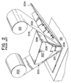
- FIG. 2 illustrates a prior art presser assembly 200 along with associated paper backing supply roll 201, paper backing take up roll 202 heater 203 and mold 101 especially adapted for laying up thermoplastic plastic tape 204.
- the plastic tape 204 is passed under heater 203 to soften the tape for detruding onto the contoured surface of mold 101.
- tape 204 is joined with paper 205 from supply roll 201 and passed under flexible skid member 206, fixed at one end to housing 207 of presser assembly 200 by screws 208.
- Flexible skid member 206, paper 205 and plastic tape 204 pass beneath and engage the bottom edge or nose 209 of segmented shoe plate stack 210 supported in housing 207 for detrusion of plastic tape 204 onto the contoured surface of mold 101 to form a composite structure.
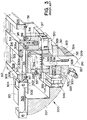
- FIG 3 shows a perspective view in section the presser assembly 200 of Figure 2 to move particularly point out the structure of presser assembly 200 without the associated rolls 201 and 202, heater 203 and flexible skid 206.
- the housing 207 is quarter rounded at its lower rear surface and has a top surface 301 to which flat housing plate 302 is bolted by screws 303.
- the housing plate 302 spans the main opening 304 and serves as a mounting for centrally located air cylinder 305 having a single piston rod 306 extending forwardly. Cylinder 305 is secured to the top plate 302 by several screws 307.
- first guide block 308 Located adjacent the front of cylinder 305 is a first guide block 308 extending across the width of the plate 302 and housing 207 and a similar second guide block 309 is located at the front end of the plate 302, the difference in the two blocks 308 and 309 being that the first block 308 has a clearance hole 310 for piston rod 306.
- the blocks 308 and 309 are held to plate 302 by a plurality of screws 311 extending from underneath and a mounting plate 312 is, in turn, secured to the upper surface of blocks 308, 309.
- the mounting plate 362 serves as a mounting member for fastening the presser assembly 200 to a main frame, not shown.
- Guide blocks 308, 309 have a pair of parallel guide rods 313 extending there between, one on each side of the assembly and a horizontal slider 314 rides with bushings 315 on guide rod 313.
- the threaded end 306a of piston rod 306 is received in slider 314 and is affixed thereto by jam nut 306b.
- the slider 314 has three specific positions:
- the latch finger 316 slides in a vertical guide block 317 which is secured by screws 318 to the lower surface of the housing plate 302.
- the latch finger 316 extends through an aperture 319 in the plate 302 and is powered in the vertical direction by a compact fluid cylinder unit 320, secured to the bottom of guide block 317.
- Shoe plate stack 210 is comprised of a plurality of parallel-faced presser elements afforded by wafer-like shoe plates 321, 322 stacked in parallel array across the tape width and guided in slot 323 in the lower surface 324 of the housing 207.
- Shoe plates 321, 322 have a convex top edge 325 and a rounded bottom work piece presser edge or nose 209.
- the two outer shoe plates 321 are twice as thick as the inner shoe plates 322 to provide side stiffness, but the outer shoe plates 321 are thinned-down at their bottom edge 209 to the same thickness as the inner shoe plates 322.
- the shoe plates 321, 322 are backed up by a brake block 326, situated in the housing 207, which serves as an additional guide for their rear edges 327, the brake block 326 being in line with the slot 323 in the housing 207.
- a vertical elongate slot 328 is in line through all the plates 321, 322 and a control rod 329 extends horizontally, from side to side, through all the slots 328.
- the control rod 329 is connected to a link 330 at each of the outer ends and the top of the links 330 are pivotally connected to the opposite side edges of the slider 314. In the position shown in Figure 5 i.e.
- a bladder spring 331 is employed comprising an open box frame 332, having a clearance around the periphery of the shoe plates 321, 322.
- a bifurcated lower portion, not shown, of the box frame 332 extends downward around control rod 329 to act as a guide for control rod 329 and provide guidance for the overall width of the stack shoe plates 321, 322.
- the box frame 332 has a flexible membrane 333 extending across its entire upper surface, in contact with and spanning the top edge 325 or biasing portion of the plates 321, 322.
- the membrane 333 is secured in place by a fabricated box 334, which is fully enclosed except for a single open side, which is placed against the membrane 333.
- the box 334 is secured in assemble with membrane 333, box frame 332 and housing 207 by screws, not shown, so that a closed chamber 335 is formed immediately above membrane 333.
- the box 334 is provided with an orifice 336 and a fluid coupling 337, mounted therein, so that air or other fluid medium may be introduced into the chamber 335 and, thus, the membrane 333 pressurized to provide a downward biasing force to the entire stack of plates 321,322.
- the membrane 333 is yieldable to accommodate surface contour variances which will cause plates 321, 322 to shift vertically, relative to one another, as the tape is laid.
- the brake block 326 has a slot 338 machined across its face adjacent the shoe plates 321, 322.
- a friction bar or brake pad 339 extends in the slot 338 across the rear edges 327 of the shoe plates 321, 322 and is activated by a compact fluid cylinder 340 which moves the brake pad 339 between "on” and “off” positions.
- the brake may be useful when the presser assembly 200 is operating near the edge of a mold and all the plates 321, 322 are not supported by a mold surface beneath the tape. In such instances the tape may be pushed over the edge of the mold in an unwanted fashion if shoe plates 321, 322 are not arrested.
- the presser assembly 200 shown in Figure 3 may be provided with a flexible skid member 206, not shown, that is fixed at one end to the housing 207 and extends beneath nose 209 of the full width of the shoe plate stack 210 such that nose 209 engages the flexible skid member 206 and in turn the plastic tape or the carrier to which the plastic tape may be temporarily affixed rides against the flexible skid member as is known in the art.
- presser assembly may be provided with a tail compactor, not shown, of a type described in US-A-4557783, for compacting the tail end of a tape course.
- the presser assembly 200 of Figure 3 may be modified to include several elements which sense, adjust and control the motions of shoe plates 321, 322 and the head 102 of the tape laying machine 100.
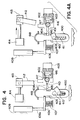
- These elements are schematically represented in Figures 4, 4a, 4b and 4c, with particular relation to a single, inner (i.e. non-terminal) shoe plate 400, by the high segment bar 401, clevis 402, fluid cylinder 403, slot 404, notch 405, arm 406, spring 407, and linear variable differential transformer (LVDT) 409.
- Figure 4 the shoe plate 400 is shown in a position that is not a "null" position with control rod 410 residing at a location between the upper and lower ends of slot 411.
- a control rod arm 412, for vertically moving control rod 410 is pivotally attached at one end to control rod 410 and at the other end pivotally attached to slider 413, which is in turn attached to the piston of fluid cylinder 414.
- High segment bar 401 has a curved nose end 415 that engages slot 404 in shoe plate 400 and a curved rear end 416 movable positioned in clevis 402 connected to fluid cylinder 403. High segment bar 401 moves laterally to cause the curved nose end 415 of high segment bar 401 to engage or disengage slot 404 and can vertically pivot about the joint 417.
- a downward bias is placed on shoe plate 400 by air pressure acting on the flexible membrane 418 of a bladder spring, not shown.
- a LVDT arm 406 engages notch 405 in shoe plate 400 and is engaged by spring 407 to provide an upward bias force against arm 406 to keep arm 406 in contact with the upper end of slot 405. Arm 406 is in turn connected to LVDT 409.
- shoe plate 400 is one of a plurality of shoe plates forming a shoe plate stack as shown at 210 in Figure 3 and that slots 404 and 411, as well as the curved nose end 415 of high segment bar 401, control rod 410 and flexible membrane 418 extend across the entire shoe plate stack.
- presser element, segment and shoe plate may be used interchangeably and mean the same thing.
- high segment bar not only denotes an element of the presser assembly, in accordance with this invention, but also may be descriptive of its function during the operation of the improved tape laying machine of this invention, as will be more fully described below, in that the high segment bar engaging a slot in the shoe plate stack responds to the upward movement of any segment of the shoe plate stack, except the segment 400 coupled to an LVDT or other signal producing sensing device, when the shoe plate stack first contacts the work surface, upon which the tape will be laid, and transfers the motion of the segment first contacting the work surface to said non-terminal segment 400 coupled to a LVDT or other sensing device.
- the non-terminal segment 400 is upwardly displaced and this upward motion is detected by the LVDT of other sensing device coupled to the segment 400 to produce a signal that is used to control the movement of the tape laying head and/or the presser assembly of the tape laying head in accordance with this invention.
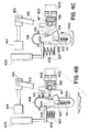
- Control rod 410 upon engaging the upper end of slot 411 raises segment 400 and the other segments of the shoe pate stack, not shown to an aligned "null" position. This position is sensed by the LVDT 409, coupled via arm 406 to the non-terminal segment 400, to provide the appropriate signal relating to the "null" condition. Air pressure is then applied to fluid cylinder 403 causing clevis 402 to move to engage the curved end 416 of high segment bar 401 forcing the curved nose end 415 of high segment bar 401 to contact the upper surface of slot 404 in shoe plate or segment 400, as shown in Figure 4b.
- the slot 404 extending through the entire shoe plate stack is constructed to have the upper surface of the slot 404 only in the non-terminal segment or other sensor coupled segment (e.g. segment 400) engage the curved nose end 415 of high segment bar 401 and only the lower or bottom surface of slot 404 in all the other segments of the shoe plate stack engage the curved nose end 415 of high segment bar 401 when high segment bar 401 is advanced into slot 404.
- segment 400 the non-terminal segment or other sensor coupled segment
- LVDT 409 produces a signal (e.g. electrical output), in relation to the upward motion of segment 400, which is applied to control means of the machine to control the movement of the head and/or presser assembly of the improved tape laying machine in accordance with this invention so as to adjust the position of the head and/or presser assembly relative to the work surface and thereby achieve a smooth,controlled transition of the presser assembly onto the work surface and a smooth initiation of the laying of a course of tape on the work surface.
- a signal e.g. electrical output
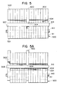
- FIG. 4c The condition represented schematically in Figure 4c is more fully understood for the shoe plate stack and the curved nose end 415 of high segment bar 401 from the schematic diagram in Figure 5.
- the shoe plate stack 500 is in the null condition with the bottom surfaces 501 all of segments 502 and segment 400 aligned and the curved nose end 415 of high segment bar 401 is in slot 404 engaging the bottom 503 of slot 404 in segments 502 and the top 504 of slot 404 in segment 400.
- Schematically shown in Figure 5a is the condition for Figure 4c in respect to the shoe plate stack 500 when the outer segment 502 of shoe plate stack 500 first engages the work surface and is raised upon going onto the work surface.
- FIG 6 there is shown a partial perspective view of the shoe plate stack 500 of Figure 5 and the high segment bar 401, clevis 402 and pivot joint 417 of Figure 4.
- the high segment bar 401 is shown in Figure 6 in the advanced position wherein the curved nose end 415 of high segment bar 401 is in slot 404 of the shoe plate stack 500 and contacts the bottom surface 503 of slot 404 in segments 502 of shoe plate stack 500 while at the same time contacting the top surface 504 of slot 404 in segment 400.
- Segments 502 and segment 400 of shoe plate stack 500 in Figure 6 are in the aligned or "null" position with the nose 501 of each segment being aligned.
- the arrangement shown in Figure 6 corresponds to the condition represented in Figure 4b.
- High segment bar 401 has two rods 601 joining the forward curved nose end 415 and the rear curved end 416. Rods 601 are slidably supported in a pivot 417 so that the curved nose end 415 of high segment bar 401 my be advanced into and retracted from slot 404 and at the same time permit high segment bar 401 to rotate in pivot 417 as the curved nose end 415 moves vertically with the motion of segments 502 and 400.
- Curved end 416 is supported within clevis 402 with clearance to permit the unrestricted rise and fall of curved end 416 with the pivoting motion of high segment bar 401 while at the same time being engageable by clevis 402 to cause curved nose end 415 to be advanced into and retracted from slot 404 of shoe plate stack 500 when clevis 402 is laterally moved by a fluid cylinder, not shown.
- FIG 7 a partial plan view of a presser assembly 700 of the improved tape laying machine in accordance with this invention with particular respect to the centre shoe segment 701 of the shoe plate stack of the presser assembly and the improvements pertaining to the high segment bar and LVDT sensor embodiments of this invention.
- the high segment bar 702 is in a retracted position with the curved nose end 703 of high segment bar 702 disengaged from slot 704 in centre segment 701.
- High segment bar 702 is slidably supported in pivot 706 to permit the curved nose end 703 to be moved into engagement with or retracted from engagement with slot 704.
- curved rear end 707 of high segment bar 702 is captured in clevis 708 with clearance to permit the rise and fall of curved rear end 707 with the pivoting motion of high segment bar 702. Also shown in Figure 7 is that curved rear end 707 has a forward face 709 engaged by rear surface 710 of the forward end 711 of clevis 708 for laterally moving high segment bar 702 into a retracted position by fluid cylinder 712 connected to the rear end 713 of clevis 708.
- the segment 701 has a slot 714 whose upper end 715 is engaged by a bar 716 attached by screw 717 to sleeve 718 slidably supported by bushing 718a on post 719 to follow the vertical movement of segment 701.
- bar 716 follows that movement and transmits the movement through arm 722, attached to sleeve 718 by screw 723, to core rod 724 of LVDT 725.
- Core rod 724 is attached to an adapter 726 by lock nuts 727 and adapter 726 is in turn joined to arm 722 by machine screw 728.
- the movement of core rod 724 in LVDT 725 produces an electrical signal in relation to the vertical movement of segment 701.
- This signal is then used to control the movement of the head and/or the presser assembly 700 of the tape laying machine in accordance with this invention.
- the signal may be used directly to operate motors which direct the movement of the head and/or presser assembly 700 of the tape laying machine or may be processed to operate controlling devices that direct the movement of the head and/or presser assembly of the tape laying machine (e.g. electrically, hydraulically or pneumatically).
- a flexible skid member 729 extends under and engages nose 730 of segment 701, as well as all the other segments (not shown) of the shoe plate stack of presser assembly 700, and is attached at one end to housing 721 of presser assembly 700 by screw 731.
- the tape or carrier layer of a carrier-tape assembly is contacted by and held against skid member 729 so that the segments of the shoe plate stack can apply and compact the tape onto the work surface.
- Flexible membrane 734 in turn presses on the upper end 738 of segment 701, extending into chamber 732, to apply compaction force on the tape, not shown, by nose 730 of segment 701.
- flexible membrane 734 engages all the segments of the shoe plate stack to apply compaction force on the tape by all the segments of the shoe plate stack.
- a spring 739 is provided in slot 741 of centre segment 701 that pushes against control rod 740 in slot 741 in centre segment 701 and the bottom of slot 741.
- control rod 740 is shown in a position it would occupy when all the segments of the shoe plate stack are on the work surface and high segment bar 702 has been retracted from slot 704. This position for control rod 740 was achieved, with reference to Figure 3, by cylinder 304 acting on slider 314 to move the attached control rod arm 330, that is in turn connected to control rod 329 ( Figure 3), 740 ( Figure 7), so as to move control rod 740 to the position shown in Figure 7 and hold it there.
- control rod 740 Since control rod 740 is now held in a fixed position in slot 741 of centre segment 701 the spring 739 acts against the control rod 740 and the bottom of slot 741 of segment 701 to bias centre segment 701 downward with a force that balances the upward force of spring 720 on bar 716 acting against the upper end 715 of slot 714 in segment 701 to bias segment 701 in an upward direction.
- This balancing of forces on centre segment 701 permits segment 701 to apply the same compaction force to the tape as is applied to the tape by each of the other segments of the shoe plate stack.
- tail compaction means such as for example taught in US-A-4557783, the entire disclosure of which is incorporated herein by references.
- the plastic tape may be of a thermosetting (e.g. epoxy) or thermoplastic (e.g. polyolefin, nylon etc.) and may contain reinforcement such as for example glass or carbon fibres in continuous strand or woven form.
- the plastic tape may have a carrier film or backing, which may be paper or other suitable material, for transporting the tape.
Landscapes
- Engineering & Computer Science (AREA)
- Robotics (AREA)
- Chemical & Material Sciences (AREA)
- Composite Materials (AREA)
- Mechanical Engineering (AREA)
- Moulding By Coating Moulds (AREA)
Applications Claiming Priority (2)
| Application Number | Priority Date | Filing Date | Title |
|---|---|---|---|
| US68011 | 1993-05-27 | ||
| US08/068,011 US5352306A (en) | 1993-05-27 | 1993-05-27 | Tape laying apparatus and method |
Publications (1)
| Publication Number | Publication Date |
|---|---|
| EP0626251A1 true EP0626251A1 (fr) | 1994-11-30 |
Family
ID=22079859
Family Applications (1)
| Application Number | Title | Priority Date | Filing Date |
|---|---|---|---|
| EP94107987A Withdrawn EP0626251A1 (fr) | 1993-05-27 | 1994-05-24 | Machine d'application de rubans et procédé d'application de rubans plastiques |
Country Status (2)
| Country | Link |
|---|---|
| US (1) | US5352306A (fr) |
| EP (1) | EP0626251A1 (fr) |
Cited By (1)
| Publication number | Priority date | Publication date | Assignee | Title |
|---|---|---|---|---|
| WO2008015082A1 (fr) * | 2006-08-01 | 2008-02-07 | Airbus Deutschland Gmbh | configuration de disposition, configuration structurelle et procédé de fabrication d'un composant pour l'aérospatiale |
Families Citing this family (25)
| Publication number | Priority date | Publication date | Assignee | Title |
|---|---|---|---|---|
| EP0644040A1 (fr) * | 1993-05-27 | 1995-03-22 | Cincinnati Milacron Inc. | Procédé et machine pour l'application de matières composites |
| US5779830A (en) * | 1995-10-24 | 1998-07-14 | Truseal Technologies, Inc. | Flexible tape applicator and method of operation |
| US7093641B2 (en) * | 2001-03-05 | 2006-08-22 | Henkel Corporation | Robotic tape applicator and method |
| US20050016671A1 (en) * | 2001-03-05 | 2005-01-27 | Sharp Terrance M. | Robotic tape applicator and method |
| US7206665B2 (en) * | 2002-09-12 | 2007-04-17 | Composite Systems, Inc. | Precision feed end-effector composite fabric tape-laying apparatus and method |
| WO2006020918A2 (fr) * | 2004-08-13 | 2006-02-23 | Henkel Corporation | Systemes et procedes pour un applicateur de bande robotise |
| US7326312B1 (en) | 2004-09-09 | 2008-02-05 | Magus Intellectual Property Gmbh | Process for laying fiber tape |
| US7341086B2 (en) | 2004-10-29 | 2008-03-11 | The Boeing Company | Automated fabric layup system and method |
| US7993480B2 (en) * | 2007-11-17 | 2011-08-09 | The Boeing Company | Method and apparatus for placing plies on curved substrates |
| US8042594B2 (en) * | 2006-06-28 | 2011-10-25 | Alliant Techsystems Inc. | Compaction device for fiber placement using interdependent segment travel |
| US7404868B2 (en) * | 2006-10-10 | 2008-07-29 | Accudyne Systems, Inc. | Tape placement head for applying thermoplastic tape to an object |
| DE102006052592B4 (de) * | 2006-11-08 | 2013-09-12 | Eads Deutschland Gmbh | Verfahren zur Ablage großer trockener Textilfaserbahnen |
| US10828846B2 (en) | 2013-01-07 | 2020-11-10 | The Boeing Company | Method and apparatus for fabricating contoured laminate structures |
| US9314974B2 (en) * | 2013-01-07 | 2016-04-19 | The Boeing Company | Method and apparatus for fabricating contoured laminate structures |
| AT514551B1 (de) | 2013-12-16 | 2015-02-15 | Gfm Gmbh | Vorrichtung zum Legen von Faserbändern |
| AT514797B1 (de) | 2013-12-16 | 2015-04-15 | Gfm Gmbh | Vorrichtung zum Legen von Faserbändern |
| AT514550B1 (de) | 2013-12-16 | 2015-02-15 | Gfm Gmbh | Vorrichtung zum Legen von Faserbändern |
| US9782937B1 (en) | 2014-05-16 | 2017-10-10 | The Boeing Company | Apparatus for forming contoured composite laminates |
| US10399284B2 (en) | 2014-05-16 | 2019-09-03 | The Boeing Company | Method and apparatus for forming contoured composite laminates |
| US9889610B2 (en) | 2014-07-29 | 2018-02-13 | The Boeing Company | Automated ply forming and compaction using flexible roller contact |
| US10744725B2 (en) * | 2016-06-01 | 2020-08-18 | The Boeing Company | Support tools for forming laminates |
| US11014314B2 (en) | 2018-06-28 | 2021-05-25 | The Boeing Company | End effector for forming prepreg plies on highly contoured surfaces |
| US12103249B2 (en) | 2021-08-30 | 2024-10-01 | The Boeing Company | Composite forming apparatus, methods, and systems |
| EP4257321A1 (fr) * | 2022-04-07 | 2023-10-11 | Siemens Gamesa Renewable Energy A/S | Procédé de fabrication d'un élément de construction de préforme et agencement de moule |
| CN117621485B (zh) * | 2023-10-08 | 2026-04-21 | 北京航空航天大学 | 一种面向复杂陡变曲率型面结构的铺丝压实机构 |
Citations (4)
| Publication number | Priority date | Publication date | Assignee | Title |
|---|---|---|---|---|
| US4750965A (en) * | 1986-03-28 | 1988-06-14 | The Ingersoll Milling Machine Company | Adaptive control for tape laying head having natural path generation |
| US4954204A (en) * | 1988-11-25 | 1990-09-04 | Cincinnati Milacron Inc. | Presser member for contoured surfaces |
| US4997510A (en) * | 1988-03-28 | 1991-03-05 | Shinnippon Koki Kabushiki Kaisha (Shinnippon Koki Co., Ltd.) | Automatic tape affixing apparatus |
| US5011563A (en) * | 1988-05-18 | 1991-04-30 | Shinnippon Koki Kabushiki Kaisha | Automatic tape affixing apparatus |
Family Cites Families (4)
| Publication number | Priority date | Publication date | Assignee | Title |
|---|---|---|---|---|
| FR2529871B1 (fr) * | 1982-07-09 | 1986-03-07 | Dassault Avions | Machine pour revetir une surface quelconque avec un materiau composite de fibres et de resine |
| US4557783A (en) * | 1983-12-05 | 1985-12-10 | Cincinnati Milacron Inc. | Composite tape laying machine and method |
| JPH0725143B2 (ja) * | 1988-03-28 | 1995-03-22 | 新日本工機株式会社 | テープの自動貼付装置 |
| FR2635714B1 (fr) * | 1988-08-26 | 1991-02-01 | Brisard Machines Outils | Dispositif de nappage pour la mise en place automatique d'une nappe de fibres sur un moule et machine comportant un tel dispositif |
-
1993
- 1993-05-27 US US08/068,011 patent/US5352306A/en not_active Expired - Lifetime
-
1994
- 1994-05-24 EP EP94107987A patent/EP0626251A1/fr not_active Withdrawn
Patent Citations (4)
| Publication number | Priority date | Publication date | Assignee | Title |
|---|---|---|---|---|
| US4750965A (en) * | 1986-03-28 | 1988-06-14 | The Ingersoll Milling Machine Company | Adaptive control for tape laying head having natural path generation |
| US4997510A (en) * | 1988-03-28 | 1991-03-05 | Shinnippon Koki Kabushiki Kaisha (Shinnippon Koki Co., Ltd.) | Automatic tape affixing apparatus |
| US5011563A (en) * | 1988-05-18 | 1991-04-30 | Shinnippon Koki Kabushiki Kaisha | Automatic tape affixing apparatus |
| US4954204A (en) * | 1988-11-25 | 1990-09-04 | Cincinnati Milacron Inc. | Presser member for contoured surfaces |
Cited By (4)
| Publication number | Priority date | Publication date | Assignee | Title |
|---|---|---|---|---|
| WO2008015082A1 (fr) * | 2006-08-01 | 2008-02-07 | Airbus Deutschland Gmbh | configuration de disposition, configuration structurelle et procédé de fabrication d'un composant pour l'aérospatiale |
| JP2009545468A (ja) * | 2006-08-01 | 2009-12-24 | エアバス ドイッチュラント ゲゼルシャフト ミット ベシュレンクテル ハフツング | レイアップ配列及び構造配列並びに航空宇宙産業用構成部品の製造方法 |
| RU2438876C2 (ru) * | 2006-08-01 | 2012-01-10 | Эйрбас Оперейшнз Гмбх | Способ изготовления конструктивного компонента для авиационно-космических летательных аппаратов |
| US8709188B2 (en) | 2006-08-01 | 2014-04-29 | Airbus Operations Gmbh | Lay-up arrangement and structural arrangement and method for producing a component for aerospace |
Also Published As
| Publication number | Publication date |
|---|---|
| US5352306A (en) | 1994-10-04 |
Similar Documents
| Publication | Publication Date | Title |
|---|---|---|
| US5352306A (en) | Tape laying apparatus and method | |
| US5314563A (en) | Tape laying and compaction apparatus | |
| US4954204A (en) | Presser member for contoured surfaces | |
| US5989384A (en) | Method of using a variable force compactor | |
| US4514246A (en) | Method of cutting and labeling sheet material | |
| EP0680818B1 (fr) | Machine d'application de fibres, organe presseur et procédé pour l'application et le compactage des mèches de fibres | |
| US4708761A (en) | Laminating apparatus for prepreg materials | |
| US5954917A (en) | Automated material delivery system | |
| EP1035963B1 (fr) | Systeme de commande d'alimentation pour machines de placement de fibres | |
| US8685199B2 (en) | Tire preparation ply manufacturing apparatus and method | |
| US4825917A (en) | Apparatus for producing thin boards | |
| JPH01294165A (ja) | テープの自動貼付装置 | |
| CA2247426A1 (fr) | Equipement pour couper, comprenant un appareil de positionnement automatique | |
| US4087308A (en) | Apparatus and method for making reinforced elastomeric fabric | |
| US4831909A (en) | Apparatus for slitting a web into narrow webs or strips | |
| GB2101512A (en) | Cutting apparatus | |
| US4708331A (en) | Device for layer-stacking web-like materials | |
| CA1046391A (fr) | Methode et materiel de faconnage et de pressage de lamelles a feuilles d'aluminium et de carton | |
| EP0644041A1 (fr) | Machine d'application de bandes composites | |
| US4997508A (en) | Automatic tape affixing apparatus | |
| US5269869A (en) | Tape laying apparatus | |
| US5443356A (en) | Automatic slide-on panel loading system | |
| US4597516A (en) | Web feeder apparatus | |
| CN111451740A (zh) | 全自动化式理线机 | |
| KR20250117782A (ko) | 테이프 놓기 헤드 |
Legal Events
| Date | Code | Title | Description |
|---|---|---|---|
| PUAI | Public reference made under article 153(3) epc to a published international application that has entered the european phase |
Free format text: ORIGINAL CODE: 0009012 |
|
| AK | Designated contracting states |
Kind code of ref document: A1 Designated state(s): DE ES FR IT |
|
| 17P | Request for examination filed |
Effective date: 19950125 |
|
| 17Q | First examination report despatched |
Effective date: 19950821 |
|
| GRAG | Despatch of communication of intention to grant |
Free format text: ORIGINAL CODE: EPIDOS AGRA |
|
| GRAH | Despatch of communication of intention to grant a patent |
Free format text: ORIGINAL CODE: EPIDOS IGRA |
|
| STAA | Information on the status of an ep patent application or granted ep patent |
Free format text: STATUS: THE APPLICATION IS DEEMED TO BE WITHDRAWN |
|
| 18D | Application deemed to be withdrawn |
Effective date: 19961112 |