EP0626263B1 - Méthode et appareil d'enregistrement thermique - Google Patents
Méthode et appareil d'enregistrement thermique Download PDFInfo
- Publication number
- EP0626263B1 EP0626263B1 EP94303813A EP94303813A EP0626263B1 EP 0626263 B1 EP0626263 B1 EP 0626263B1 EP 94303813 A EP94303813 A EP 94303813A EP 94303813 A EP94303813 A EP 94303813A EP 0626263 B1 EP0626263 B1 EP 0626263B1
- Authority
- EP
- European Patent Office
- Prior art keywords
- temperature
- recording
- recording head
- head
- set forth
- Prior art date
- Legal status (The legal status is an assumption and is not a legal conclusion. Google has not performed a legal analysis and makes no representation as to the accuracy of the status listed.)
- Expired - Lifetime
Links
- 238000000034 method Methods 0.000 title claims description 47
- 230000008859 change Effects 0.000 claims description 39
- 238000012545 processing Methods 0.000 claims description 13
- 239000003086 colorant Substances 0.000 claims description 12
- 238000012937 correction Methods 0.000 claims description 12
- 238000001514 detection method Methods 0.000 claims description 8
- 239000000976 ink Substances 0.000 description 108
- 238000005259 measurement Methods 0.000 description 46
- 238000010586 diagram Methods 0.000 description 27
- 238000004364 calculation method Methods 0.000 description 23
- 239000006185 dispersion Substances 0.000 description 12
- 238000010438 heat treatment Methods 0.000 description 12
- 239000007788 liquid Substances 0.000 description 12
- 239000000463 material Substances 0.000 description 9
- 238000010276 construction Methods 0.000 description 8
- 238000004422 calculation algorithm Methods 0.000 description 7
- 230000033001 locomotion Effects 0.000 description 7
- 230000006870 function Effects 0.000 description 5
- 230000001965 increasing effect Effects 0.000 description 5
- 230000004044 response Effects 0.000 description 5
- 238000009835 boiling Methods 0.000 description 4
- 238000006243 chemical reaction Methods 0.000 description 4
- 230000015654 memory Effects 0.000 description 4
- 239000007787 solid Substances 0.000 description 4
- 230000006641 stabilisation Effects 0.000 description 4
- 238000011105 stabilization Methods 0.000 description 4
- 238000009825 accumulation Methods 0.000 description 3
- 230000009471 action Effects 0.000 description 3
- 238000009529 body temperature measurement Methods 0.000 description 3
- 230000000694 effects Effects 0.000 description 3
- 230000014759 maintenance of location Effects 0.000 description 3
- 238000004519 manufacturing process Methods 0.000 description 3
- 238000012986 modification Methods 0.000 description 3
- 230000004048 modification Effects 0.000 description 3
- 230000008569 process Effects 0.000 description 3
- 230000009467 reduction Effects 0.000 description 3
- 238000005070 sampling Methods 0.000 description 3
- 238000012951 Remeasurement Methods 0.000 description 2
- XAGFODPZIPBFFR-UHFFFAOYSA-N aluminium Chemical compound [Al] XAGFODPZIPBFFR-UHFFFAOYSA-N 0.000 description 2
- 229910052782 aluminium Inorganic materials 0.000 description 2
- 230000006399 behavior Effects 0.000 description 2
- 230000015572 biosynthetic process Effects 0.000 description 2
- 230000008602 contraction Effects 0.000 description 2
- 230000003247 decreasing effect Effects 0.000 description 2
- 238000011161 development Methods 0.000 description 2
- 238000009826 distribution Methods 0.000 description 2
- 230000001939 inductive effect Effects 0.000 description 2
- 239000011159 matrix material Substances 0.000 description 2
- 239000000203 mixture Substances 0.000 description 2
- 230000005855 radiation Effects 0.000 description 2
- 230000002829 reductive effect Effects 0.000 description 2
- 230000000087 stabilizing effect Effects 0.000 description 2
- 239000000758 substrate Substances 0.000 description 2
- 230000002159 abnormal effect Effects 0.000 description 1
- 230000002411 adverse Effects 0.000 description 1
- 230000009286 beneficial effect Effects 0.000 description 1
- 230000002457 bidirectional effect Effects 0.000 description 1
- 230000005540 biological transmission Effects 0.000 description 1
- 238000004140 cleaning Methods 0.000 description 1
- 238000001816 cooling Methods 0.000 description 1
- 230000001186 cumulative effect Effects 0.000 description 1
- 230000000881 depressing effect Effects 0.000 description 1
- 230000002542 deteriorative effect Effects 0.000 description 1
- 230000007613 environmental effect Effects 0.000 description 1
- 238000001704 evaporation Methods 0.000 description 1
- 230000008020 evaporation Effects 0.000 description 1
- 238000002474 experimental method Methods 0.000 description 1
- 230000010365 information processing Effects 0.000 description 1
- 230000002452 interceptive effect Effects 0.000 description 1
- 238000005304 joining Methods 0.000 description 1
- 239000011344 liquid material Substances 0.000 description 1
- 230000006911 nucleation Effects 0.000 description 1
- 238000010899 nucleation Methods 0.000 description 1
- 230000000704 physical effect Effects 0.000 description 1
- 239000002985 plastic film Substances 0.000 description 1
- 238000003825 pressing Methods 0.000 description 1
- 238000011084 recovery Methods 0.000 description 1
- 230000000717 retained effect Effects 0.000 description 1
- 230000000630 rising effect Effects 0.000 description 1
- XUIMIQQOPSSXEZ-OUBTZVSYSA-N silicon-29 atom Chemical compound [29Si] XUIMIQQOPSSXEZ-OUBTZVSYSA-N 0.000 description 1
- 239000011343 solid material Substances 0.000 description 1
- 238000012360 testing method Methods 0.000 description 1
Images


Classifications
-
- B—PERFORMING OPERATIONS; TRANSPORTING
- B41—PRINTING; LINING MACHINES; TYPEWRITERS; STAMPS
- B41J—TYPEWRITERS; SELECTIVE PRINTING MECHANISMS, i.e. MECHANISMS PRINTING OTHERWISE THAN FROM A FORME; CORRECTION OF TYPOGRAPHICAL ERRORS
- B41J2/00—Typewriters or selective printing mechanisms characterised by the printing or marking process for which they are designed
- B41J2/005—Typewriters or selective printing mechanisms characterised by the printing or marking process for which they are designed characterised by bringing liquid or particles selectively into contact with a printing material
- B41J2/01—Ink jet
- B41J2/17—Ink jet characterised by ink handling
- B41J2/175—Ink supply systems ; Circuit parts therefor
- B41J2/17503—Ink cartridges
- B41J2/17543—Cartridge presence detection or type identification
- B41J2/17546—Cartridge presence detection or type identification electronically
-
- B—PERFORMING OPERATIONS; TRANSPORTING
- B41—PRINTING; LINING MACHINES; TYPEWRITERS; STAMPS
- B41J—TYPEWRITERS; SELECTIVE PRINTING MECHANISMS, i.e. MECHANISMS PRINTING OTHERWISE THAN FROM A FORME; CORRECTION OF TYPOGRAPHICAL ERRORS
- B41J2/00—Typewriters or selective printing mechanisms characterised by the printing or marking process for which they are designed
- B41J2/005—Typewriters or selective printing mechanisms characterised by the printing or marking process for which they are designed characterised by bringing liquid or particles selectively into contact with a printing material
- B41J2/01—Ink jet
- B41J2/015—Ink jet characterised by the jet generation process
- B41J2/04—Ink jet characterised by the jet generation process generating single droplets or particles on demand
- B41J2/045—Ink jet characterised by the jet generation process generating single droplets or particles on demand by pressure, e.g. electromechanical transducers
- B41J2/04501—Control methods or devices therefor, e.g. driver circuits, control circuits
- B41J2/04528—Control methods or devices therefor, e.g. driver circuits, control circuits aiming at warming up the head
-
- B—PERFORMING OPERATIONS; TRANSPORTING
- B41—PRINTING; LINING MACHINES; TYPEWRITERS; STAMPS
- B41J—TYPEWRITERS; SELECTIVE PRINTING MECHANISMS, i.e. MECHANISMS PRINTING OTHERWISE THAN FROM A FORME; CORRECTION OF TYPOGRAPHICAL ERRORS
- B41J2/00—Typewriters or selective printing mechanisms characterised by the printing or marking process for which they are designed
- B41J2/005—Typewriters or selective printing mechanisms characterised by the printing or marking process for which they are designed characterised by bringing liquid or particles selectively into contact with a printing material
- B41J2/01—Ink jet
- B41J2/015—Ink jet characterised by the jet generation process
- B41J2/04—Ink jet characterised by the jet generation process generating single droplets or particles on demand
- B41J2/045—Ink jet characterised by the jet generation process generating single droplets or particles on demand by pressure, e.g. electromechanical transducers
- B41J2/04501—Control methods or devices therefor, e.g. driver circuits, control circuits
- B41J2/0454—Control methods or devices therefor, e.g. driver circuits, control circuits involving calculation of temperature
-
- B—PERFORMING OPERATIONS; TRANSPORTING
- B41—PRINTING; LINING MACHINES; TYPEWRITERS; STAMPS
- B41J—TYPEWRITERS; SELECTIVE PRINTING MECHANISMS, i.e. MECHANISMS PRINTING OTHERWISE THAN FROM A FORME; CORRECTION OF TYPOGRAPHICAL ERRORS
- B41J2/00—Typewriters or selective printing mechanisms characterised by the printing or marking process for which they are designed
- B41J2/005—Typewriters or selective printing mechanisms characterised by the printing or marking process for which they are designed characterised by bringing liquid or particles selectively into contact with a printing material
- B41J2/01—Ink jet
- B41J2/015—Ink jet characterised by the jet generation process
- B41J2/04—Ink jet characterised by the jet generation process generating single droplets or particles on demand
- B41J2/045—Ink jet characterised by the jet generation process generating single droplets or particles on demand by pressure, e.g. electromechanical transducers
- B41J2/04501—Control methods or devices therefor, e.g. driver circuits, control circuits
- B41J2/04563—Control methods or devices therefor, e.g. driver circuits, control circuits detecting head temperature; Ink temperature
-
- B—PERFORMING OPERATIONS; TRANSPORTING
- B41—PRINTING; LINING MACHINES; TYPEWRITERS; STAMPS
- B41J—TYPEWRITERS; SELECTIVE PRINTING MECHANISMS, i.e. MECHANISMS PRINTING OTHERWISE THAN FROM A FORME; CORRECTION OF TYPOGRAPHICAL ERRORS
- B41J2/00—Typewriters or selective printing mechanisms characterised by the printing or marking process for which they are designed
- B41J2/005—Typewriters or selective printing mechanisms characterised by the printing or marking process for which they are designed characterised by bringing liquid or particles selectively into contact with a printing material
- B41J2/01—Ink jet
- B41J2/015—Ink jet characterised by the jet generation process
- B41J2/04—Ink jet characterised by the jet generation process generating single droplets or particles on demand
- B41J2/045—Ink jet characterised by the jet generation process generating single droplets or particles on demand by pressure, e.g. electromechanical transducers
- B41J2/04501—Control methods or devices therefor, e.g. driver circuits, control circuits
- B41J2/04565—Control methods or devices therefor, e.g. driver circuits, control circuits detecting heater resistance
-
- B—PERFORMING OPERATIONS; TRANSPORTING
- B41—PRINTING; LINING MACHINES; TYPEWRITERS; STAMPS
- B41J—TYPEWRITERS; SELECTIVE PRINTING MECHANISMS, i.e. MECHANISMS PRINTING OTHERWISE THAN FROM A FORME; CORRECTION OF TYPOGRAPHICAL ERRORS
- B41J2/00—Typewriters or selective printing mechanisms characterised by the printing or marking process for which they are designed
- B41J2/005—Typewriters or selective printing mechanisms characterised by the printing or marking process for which they are designed characterised by bringing liquid or particles selectively into contact with a printing material
- B41J2/01—Ink jet
- B41J2/015—Ink jet characterised by the jet generation process
- B41J2/04—Ink jet characterised by the jet generation process generating single droplets or particles on demand
- B41J2/045—Ink jet characterised by the jet generation process generating single droplets or particles on demand by pressure, e.g. electromechanical transducers
- B41J2/04501—Control methods or devices therefor, e.g. driver circuits, control circuits
- B41J2/04573—Timing; Delays
-
- B—PERFORMING OPERATIONS; TRANSPORTING
- B41—PRINTING; LINING MACHINES; TYPEWRITERS; STAMPS
- B41J—TYPEWRITERS; SELECTIVE PRINTING MECHANISMS, i.e. MECHANISMS PRINTING OTHERWISE THAN FROM A FORME; CORRECTION OF TYPOGRAPHICAL ERRORS
- B41J2/00—Typewriters or selective printing mechanisms characterised by the printing or marking process for which they are designed
- B41J2/005—Typewriters or selective printing mechanisms characterised by the printing or marking process for which they are designed characterised by bringing liquid or particles selectively into contact with a printing material
- B41J2/01—Ink jet
- B41J2/015—Ink jet characterised by the jet generation process
- B41J2/04—Ink jet characterised by the jet generation process generating single droplets or particles on demand
- B41J2/045—Ink jet characterised by the jet generation process generating single droplets or particles on demand by pressure, e.g. electromechanical transducers
- B41J2/04501—Control methods or devices therefor, e.g. driver circuits, control circuits
- B41J2/0458—Control methods or devices therefor, e.g. driver circuits, control circuits controlling heads based on heating elements forming bubbles
-
- B—PERFORMING OPERATIONS; TRANSPORTING
- B41—PRINTING; LINING MACHINES; TYPEWRITERS; STAMPS
- B41J—TYPEWRITERS; SELECTIVE PRINTING MECHANISMS, i.e. MECHANISMS PRINTING OTHERWISE THAN FROM A FORME; CORRECTION OF TYPOGRAPHICAL ERRORS
- B41J2/00—Typewriters or selective printing mechanisms characterised by the printing or marking process for which they are designed
- B41J2/005—Typewriters or selective printing mechanisms characterised by the printing or marking process for which they are designed characterised by bringing liquid or particles selectively into contact with a printing material
- B41J2/01—Ink jet
- B41J2/015—Ink jet characterised by the jet generation process
- B41J2/04—Ink jet characterised by the jet generation process generating single droplets or particles on demand
- B41J2/045—Ink jet characterised by the jet generation process generating single droplets or particles on demand by pressure, e.g. electromechanical transducers
- B41J2/04501—Control methods or devices therefor, e.g. driver circuits, control circuits
- B41J2/04588—Control methods or devices therefor, e.g. driver circuits, control circuits using a specific waveform
-
- B—PERFORMING OPERATIONS; TRANSPORTING
- B41—PRINTING; LINING MACHINES; TYPEWRITERS; STAMPS
- B41J—TYPEWRITERS; SELECTIVE PRINTING MECHANISMS, i.e. MECHANISMS PRINTING OTHERWISE THAN FROM A FORME; CORRECTION OF TYPOGRAPHICAL ERRORS
- B41J2/00—Typewriters or selective printing mechanisms characterised by the printing or marking process for which they are designed
- B41J2/005—Typewriters or selective printing mechanisms characterised by the printing or marking process for which they are designed characterised by bringing liquid or particles selectively into contact with a printing material
- B41J2/01—Ink jet
- B41J2/015—Ink jet characterised by the jet generation process
- B41J2/04—Ink jet characterised by the jet generation process generating single droplets or particles on demand
- B41J2/045—Ink jet characterised by the jet generation process generating single droplets or particles on demand by pressure, e.g. electromechanical transducers
- B41J2/04501—Control methods or devices therefor, e.g. driver circuits, control circuits
- B41J2/04591—Width of the driving signal being adjusted
-
- B—PERFORMING OPERATIONS; TRANSPORTING
- B41—PRINTING; LINING MACHINES; TYPEWRITERS; STAMPS
- B41J—TYPEWRITERS; SELECTIVE PRINTING MECHANISMS, i.e. MECHANISMS PRINTING OTHERWISE THAN FROM A FORME; CORRECTION OF TYPOGRAPHICAL ERRORS
- B41J2/00—Typewriters or selective printing mechanisms characterised by the printing or marking process for which they are designed
- B41J2/005—Typewriters or selective printing mechanisms characterised by the printing or marking process for which they are designed characterised by bringing liquid or particles selectively into contact with a printing material
- B41J2/01—Ink jet
- B41J2/015—Ink jet characterised by the jet generation process
- B41J2/04—Ink jet characterised by the jet generation process generating single droplets or particles on demand
- B41J2/045—Ink jet characterised by the jet generation process generating single droplets or particles on demand by pressure, e.g. electromechanical transducers
- B41J2/04501—Control methods or devices therefor, e.g. driver circuits, control circuits
- B41J2/04598—Pre-pulse
-
- B—PERFORMING OPERATIONS; TRANSPORTING
- B41—PRINTING; LINING MACHINES; TYPEWRITERS; STAMPS
- B41J—TYPEWRITERS; SELECTIVE PRINTING MECHANISMS, i.e. MECHANISMS PRINTING OTHERWISE THAN FROM A FORME; CORRECTION OF TYPOGRAPHICAL ERRORS
- B41J2/00—Typewriters or selective printing mechanisms characterised by the printing or marking process for which they are designed
- B41J2/005—Typewriters or selective printing mechanisms characterised by the printing or marking process for which they are designed characterised by bringing liquid or particles selectively into contact with a printing material
- B41J2/01—Ink jet
- B41J2/17—Ink jet characterised by ink handling
- B41J2/195—Ink jet characterised by ink handling for monitoring ink quality
-
- B—PERFORMING OPERATIONS; TRANSPORTING
- B41—PRINTING; LINING MACHINES; TYPEWRITERS; STAMPS
- B41J—TYPEWRITERS; SELECTIVE PRINTING MECHANISMS, i.e. MECHANISMS PRINTING OTHERWISE THAN FROM A FORME; CORRECTION OF TYPOGRAPHICAL ERRORS
- B41J25/00—Actions or mechanisms not otherwise provided for
- B41J25/34—Bodily-changeable print heads or carriages
-
- B—PERFORMING OPERATIONS; TRANSPORTING
- B41—PRINTING; LINING MACHINES; TYPEWRITERS; STAMPS
- B41J—TYPEWRITERS; SELECTIVE PRINTING MECHANISMS, i.e. MECHANISMS PRINTING OTHERWISE THAN FROM A FORME; CORRECTION OF TYPOGRAPHICAL ERRORS
- B41J2/00—Typewriters or selective printing mechanisms characterised by the printing or marking process for which they are designed
- B41J2/005—Typewriters or selective printing mechanisms characterised by the printing or marking process for which they are designed characterised by bringing liquid or particles selectively into contact with a printing material
- B41J2/01—Ink jet
- B41J2/135—Nozzles
- B41J2/14—Structure thereof only for on-demand ink jet heads
- B41J2002/14379—Edge shooter
Definitions
- This invention relates to a recording method and apparatus which makes it possible to improve an image quality and throughput, and more particularly to an ink jet recording apparatus and its method wherein characteristics of temperature sensors can be obtained precisely in a short time.
- Recording apparatuses such as a printer, a copying machine, and a facsimile, each have a configuration to form an image consisting of dot patterns on a recording medium such as a sheet of paper and a plastic sheet on the basis of image information.
- the recording apparatuses can be classified into an ink jet type, a wire dot matrix type, a thermal type, and a laser beam type apparatuses according to their respective recording methods.
- the ink jet type apparatus an ink jet recording apparatus among them has a configuration in which ink droplets (recording droplets) are ejected and sprayed from ejection outlets of its recording heads so as to be deposited on the recording medium in recording.
- the above ink jet recording apparatus can satisfy these requirements.
- Temperature management of the recording head is very important to stabilize the ink ejection and the ejection quantity necessary to satisfy the above requirements.
- Japanese Patent Application Laid-open No. 5-31906 values used for calculation (for example, tables) are corrected by using a difference between a temperature detected in a thermally stabilized status by the temperature detecting means on the recording head and the calculated temperature presumed by calculation.
- a temperature detected by the temperature detecting means on the recording head is corrected with reference to a temperature detected by an ambient temperature detecting means incorporated in the main unit of the recording apparatus, when recording is not performed or at a timing when the temperature is not changed.
- a caluculated temperatue is corrected by using a ratio of the temperature detected by the temperature detecting means on the recording head to the above calculated temperature.
- These methods are used for correcting head characteristics such as a variation in the above temperature detecting means, differences between thermal time constants or those between thermal efficiencies at ink ejection in respective recording heads which are difficulties existent in replacement type recording heads.
- temperature behavior (temperature raise) of an object is previously obtained, in respect to the downward movement of the object temperature at unit time intervals after the temperature raise caused by applied energy at unit time intervals, and then calculation is made to obtain the total sum of a difference between the current object temperature and the past temperature which has been raised at unit time intervals to presume the present object temperature.
- a heater used for the temperature control is a heater member for heating jointed to the recording head portion or a heater for ink ejection in an ink jet type recording apparatus which forms sprayed droplets by utilizing thermal energy for recording, in other words, means for ejecting ink droplets by utilizing expansion of bubbles due to boiling of an ink film. If the ink ejection heater is used, it is energized to an extent that bubbles are not expanded.
- the temperature management of the recording heads is important to allow the ink jet recording apparatus to effect stable ink ejection, therefore, it is intended to obtain temperatures of the recording heads precisely in various methods.
- temperatures of recording heads are to be detected by temperature detecting means added to the recording heads, for example, if temperatures are to be detected by using temperature dependencies of output voltages of diode sensors, an offset (a variation of output values at the same temperature) has a substantial variation between respective sensors, though a proportional coefficient (hereinafter referred to "inclination") of a temperature-output voltage does not have any substantial variation between respective sensors (for the head temperature management). Accordingly, the head temperature as an absolute value cannot be obtained only from the same output voltage, unless characteristics (rank) of a Di sensor is acquired.
- the above rank is measured previously, for example, at manufacturing a recording head, and then the head is notched in associating with rank values which have been measured or rank values are previously stored in an EEPROM or other memories. It provides precise correction of the recording head temperatures if the rank values are read when the main unit is installed. If diode rank values are stored in the recording heads, however, it takes much time and labor to store them and a lot of cost since a storing means (for example, ROM) is needed for each recording head. In addition, in a method of detecting the diode ranks by utilizing combination of contacts for diode rank values made on the recording heads, there have been difficulties such as large-sized apparatuses and higher cost since it requires the contacts and wiring for reading by the amount of information.
- the recording apparatus main unit is used to measure the diode ranks of the recording heads. More specifically, it is a method in which correction is made so that a thermistor temperature matches the diode sensor temperature when the temperature value of the thermistor in the main unit is considered to be the same as the recording head temperature.
- the new recording head when a new recording head is mounted on the main unit, conventionally the new recording head may have been left in an environment different from that of the main unit, in other words, in an environment whose temperature is extremely different from that of an environment in which the main unit is installed, such as in a warehouse cold in winter or in a car hot in summer, which is an extreme case.
- the recording head it needs a substantial waiting time after the recording head is mounted on the main unit to measure the diode rank.
- the measurement error of the rank value may be too big to obtain the recording head temperature precisely.
- the method has a difficulty that it sometimes leads to a failure of stabilization in the ink ejection from the recording head or in the amount of the ink ejection.
- a recording apparatus for recording an image on a recording medium, using a recording head mountable on the apparatus, said recording head comprising means for generating thermal energy for recording and a temperature sensor for outputting an output value corresponding to a detected temperature, said apparatus comprising:
- this invention provides a recording method of recording with a recording head mounted in a recording apparatus to record images, said recording head comprising means for generating thermal energy said method comprising the steps of:
- Fig. 7 illustrates a serial type ink jet color printer using the present example.
- Recording heads 1 are each a device which is provided with a plurality of nozzle rows and adapted to record an image by ejecting ink droplets through the nozzle rows and causing the ink droplets to land on a recording medium P and form ink dots thereon. (In the diagram, the components mentioned are covered by a recording head fixing lever and are not directly indicated.)
- a plurality of printing heads jointly form each of the recording heads 1 so as to permit ejection of ink droplets of a plurality of colors as will be described more specifically hereinbelow. Inks of different colors are ejected from different printing heads and a color image is formed on the recording medium P owing to the mixture of such different colors of the ink droplets.
- Print data are transmitted from an electric circuit of the printer proper to the printing heads through the medium of a flexible cable 10.
- Printing head rows 1K (black), 1C (cyan), 1M (magenta), and 1Y (yellow), in the construction of this diagram, are formed by the collection of recording heads severally assigned to the four colors.
- the recording heads 1 are freely attachable or detachable to a carriage 3. In the forward scan, the inks of different colors mentioned above are ejected in the order mentioned.
- red for example, magenta (hereinafter referred to as M) is ejected to land on the recording medium P first and then yellow (hereinafter referred to as Y) is ejected to land on the previously formed dots of M, with the result that red dots will consequently appear.
- green hereinafter referred to as G
- B blue
- C and M to land thereon respectively in the order mentioned.
- the printing heads are arrayed at a fixed interval (P1).
- P1 fixed interval
- the formation of a solid G print therefore, requires Y to land on the recording medium with a time lag of 2*P1 following the landing of C thereon.
- a solid Y print is superposed on a solid C print.
- the carriage 3 has the motion thereof in the direction of main scan controlled by unshown position sensing means detecting continuously the scanning speed and the printing position of the carriage.
- the power source for the carriage 3 is a carriage drive motor.
- the carriage 3, with the power transmitted thereto through the medium of a timing belt 8, is moved on guide shafts 6 and 7.
- the impression of prints proceeds during the motion of the carriage 3 for main scan.
- the printing action in the vertical direction selectively effects unidirectional printing and bidirectional printing.
- the unidirectional printing produces a print only during the motion of the carriage away (the forward direction) from the home position thereof (hereinafter referred to as HP) and not during the motion thereof toward the HP (the backward direction).
- HP home position thereof
- the bidirectional-printing produces a printing action in both the forward and the backward direction. It, therefore, permits high-speed printing.
- the recording medium P is advanced by a platen roller 11 which is driven by a paper feed motor not shown in the diagram. After the paper fed in the direction indicated by the arrow C in the diagram has reached the printing position, the printing head rows start a printing action.
- a plurality of ejection nozzles 1A for ejecting ink droplets are disposed in a row on a heater board 20G of the printing heads and electric thermal transducers (hereinafter referred to as "ejection heaters 1B") for generating thermal energy by use of voltage applied thereto are disposed one each in the ejection nozzles 1A so as to cause ejection of ink droplets through the ejection nozzles 1A.
- the printing heads in response to a drive signal exerted thereon, cause the ejection heaters 1B to generate heat and induce the ejection of ink droplets.
- an ejection heater row 20D having a plurality of ejection heaters 1B arrayed thereon is disposed on the heater board 20G.
- Dummy resistors 20E incapable of ejecting ink droplets are disposed one each near the opposite ends of the ejection heater row 20D. Since the dummy resistors 20E are fabricated under the same conditions as the ejection heater 1B, the energy (Watt/hr) formed severally by the ejection heaters 1B in response to the application thereto of a fixed voltage can be detected by measuring the magnitude of resistance produced in the dummy resistors 20E.
- the formed energy of the ejection heaters 1B can be computed as V 2 /R, wherein V stands for the applied voltage (Volt) and R for the resistance ( ⁇ ) of the ejection heaters, the characteristics of the ejection heaters 1B are dispersed similarly to those of the resistors 20E. These resistors 1B and 20E possibly have their characteristics dispersed within a range of ⁇ 15%, for example, by reflecting the inconstancy of craftsmanship encountered by them in the process of manufacture.
- the recording heads are enabled to enjoy an elongated service life and produce images of exalted quality by detecting the dispersion of the characteristics of the ejection heaters 1B and optimizing the drive conditions of the recording heads based on the outcomes of the detection.
- the recording heads require temperature control.
- diode sensors 20C are disposed on the heater board 20G and operated to measure the temperature of the neighborhood of the ejection heaters 1B. The results of this measurement are utilized for controlling the magnitude of the energy which is required for the ink ejection or the temperature control. In the present example, the average of the degrees of temperature detected by the diode sensors 20C forms the detected temperature.
- sub-heaters 20F electric thermal transducers
- the energy supplied to the sub-heaters 20F is likewise controlled by the diode sensors 20C. Since the sub-heaters 20F are manufactured under the same conditions as the ejection heaters 1B, the dispersion of the magnitudes of resistance manifested by the sub-heaters 20F can be detected by measuring the magnitudes of resistance of the dummy resistors 20E mentioned above.
- the temperatures of the heads can be detected and controlled with high efficiency and the heads can be miniaturized and manufactured by a simplified process.
- the recording heads mounted on the carriage will be described below.
- the four printing heads (Fig. 8) serving the purpose of ejecting inks of the four colors R, C, M, and Y and ink tanks 2bk, 2c, 2m, and 2y for storing and supplying the respective inks are mounted in the carriage 3.
- These four ink tanks are so constructed as to be attached to and detached from the carriage 3. When they are emptied of their ink supplies, they can be replaced with newly supplied ink tanks.
- a recording head fixing lever 4 is intended to position and fix the recording heads 1 on the carriage 3. Bosses 3b of the carriage 3 are rotatably inserted into holes 4a of the recording head fixing lever 4.
- the lever 4 which is normally kept in a closed state is opened to allow the operator access to the recording heads 1 and permit their replacement. Further, the engagement of the recording head fixing lever 4 with stoppers 3d of the carriage 3 ensures infallible fixation of the recording heads 1 on the carriage 3.
- a group of contacts 111 on the recording heads 1 join a group of matched contacts on the unshown recording head fixing lever.
- the drive signals for driving the ejection heaters and sub-heaters of the printing heads assigned to the four colors and the data of head characteristics and the numerical values as the results of detection of the diode sensors can be transmitted from the recording apparatus proper or rendered detectable.
- the operation of ejection and the amount of ejection can be stabilized and the impartation of high quality to images to be recorded can be attained by controlling the temperatures of the recording heads within a fixed range.
- the means for computation and detection of the temperatures of the recording heads and the method for controlling the optimum drives for such temperatures which are adopted in the present example for the purpose of realizing stable recording of images of high quality will be outlined below.
- the control of head drive aimed at stabilizing the amount of ejection uses the tip temperature of a head as the criterion of control.
- the tip temperature of a head is handled as a substitute characteristic to be used for the detection of the amount of ejection per dot of the relevant ink being ejected at the time of detection. Even when the tip temperature is fixed, the amount of ejection differs because the temperature of the ink in the tank depends on the environmental temperature.
- the tip temperature of the head which is set to equalize the amount of ejection at a varying temperature (namely at a varying ink temperature) for the purpose of eliminating the difference mentioned above constitutes itself a target temperature.
- the target temperatures are set in advance in the form of a table of target temperatures.
- the table of target temperatures to be used in the present example are shown in Fig. 18.
- the algorithm of temperature computation to determine the change of temperature of the recording head is handled as an accumulation of discrete variables per unit time.
- the change of temperature of the recording head which corresponds to the discrete variables mentioned above is computed and tabulated in advance.
- the temperature computation is carried out by use of a two-dimensional table which is formed with a two-dimensional matrix representing the magnitude of energy consumed per unit time and the elapsed time.
- Recording heads formed as a model by assembling a plurality of members differing in thermal conduction time are used as substitutes at a smaller number of heat time constants than actual.
- the interval of computations required and the duration of retention of data required are separately computed for each model unit (heat time constant).
- the head temperature is computed by setting a plurality of heat sources, computing the width of temperature rise by the model unit mentioned above for each of the heat sources, and then totaling the widths obtained by the computation (algorithm for computation of a plurality of heat sources).
- the algorithm allows the change of temperature of the recording head even in an inexpensive recording apparatus to be completely computed and coped with without requiring the otherwise inevitable provision of a temperature sensor on the recording head.
- the stabilization of the amount of ejection can be attained when the head under a varying environment is driven at the tip temperature indicated in the table of target temperatures mentioned above. Actually, however, the tip temperature is not constant because it sometimes varies with the printing duty.
- the means to drive the head by use of the multipulse PWM and control the amount of ejection without relying on temperature for the purpose of stabilizing the amount of ejection constitutes itself the PWM control.
- a PWM table defining the pulses of optimum waveforms/widths at existent times based on the differences between the head temperature and the target temperatures under existent environments are set in advance. The drive conditions for ejection are fixed based on the data of this table.
- the control which is attained by driving a sub-heater and approximating the head temperature to the target temperature when the PWM drive fails to obtain a desired amount of ejection forms the control of a sub-heater.
- the sub-heater control enables the head temperature to be controlled in a prescribed temperature range.
- the tip temperature of the recording head can be estimated by computing the formulas (1) and (2) given above in accordance with the printing duty for a relevant heat time constant, providing that the recording head is handled as a series of lumped constants.
- the number of necessary arithmetic operations is colossal because all the component members have different time constants and time constants arise among the members.
- the recording head constructed as described above results from assembling numerous members differing in time of thermal conduction, this recording head can be practically treated as a single member with respect to thermal conduction so long as the differential value of the functions of elapsed time and data of temperature rise with elapsed time obtained by the aforementioned logarithmic conversion is constant (namely, within the ranges A, B, and C on Fig. 19 wherein the inclinations are fixed).
- the present examples has elected to handle the recording head with two heat time constants in the model associated with thermal conduction. (Though the results indicate that the regression can be performed more accurately by use of a model having three heat time constants, the present example has elected to model the recording head with two heat time constants by concluding that the inclinations in the areas of B and C of the table are substantially equal and giving a preference to the efficiency of arithmetic operations to be involved.)
- one of the two magnitudes of thermal conduction pertains to a model having a time constant such that the temperature is equilibrated in 0.8 second (equivalent to the area of A in Fig. 19) and the other magnitude of thermal conduction pertains to a model having a time constant such that the temperature is equilibrated in 512 seconds (equivalent to the areas of B and C in Fig. 19).
- the present example computes the head temperature by expanding the aforementioned general formulas on thermal conduction as follows.
- the expansion shown above indicates that the formula ⁇ 1 ⁇ coincides with ⁇ 2-1 ⁇ + ⁇ 2-2 ⁇ + ⁇ 2-3 ⁇ + ... + ⁇ 2-n ⁇ .
- the formula ⁇ 2-n ⁇ represents the temperature of a given object at the point of time of nt which is found when the object is heated from the point of time of 0 to that of t and the heating is suspended between the point of time of t and that of nt.
- the formula ⁇ 2-3 ⁇ represents the temperature of the object at the point of time of nt which is found when the object is heated from the point of time of (n-3)t to that of (n-2)t and the heating is suspended between the point of time of (n-2)t and that of nt.
- the formula ⁇ 2-2 ⁇ represents the temperature of the object at the point of time of nt which is found when the object is heated from the point of time of (n-2)t to that of (n-1)t and the heating is suspended between the point of time of (n-1)t and that of nt.
- the formula ⁇ 2-1 ⁇ represents the temperature of the object at the point of time of nt which is found when the object is heated between the point of time of (n-1)t and that of nt.
- the present example elects to perform four times (the product; 2 power sources * 2 heat time constants) the computation of the tip temperature of the recording head on the basis of the modeling mentioned above.
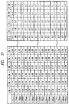
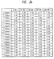
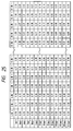
- Tables of arithmetic operations which are two-dimensional matrixes having the magnitudes of energy imparted and the lengths of time elapsed arrayed for the computation of the head temperature mentioned above are shown in Fig. 22 to Fig. 25.
- Fig. 22 represents a table for the computation of heat sources; ejection heaters, time constants; and short-range groups of members
- Fig. 23 a table for the computation of heat sources; ejection heaters, time constants; and long-range groups of members
- Fig. 24 a table for the computation of heat sources; sub-heaters, time constants; and short-range groups of members
- Fig. 25 a table for the computation of heat sources; sub-heaters, time constants; and long-range groups of members.
- the head temperature at a given time can be computed as hereinbelow.
- the amount of processing of arithmetic operations can be appreciably decreased without noticeably sacrificing the accuracy of operation as compared with the amount of processing of arithmetic operations performed faithfully with respect to all the heat time constants of the members differing in thermal conduction time and those among the individual members and (ii) the processing of arithmetic operations can be performed with a small number of rounds without a sacrifice of the accuracy of computation on account of the use of time constants as a criterion of determination (in the case of the foregoing example, if the modeling is not effected for each of the time constants, then the intervals of 50 msec to be fixed in the area of A having a small time constant will have to be used for the necessary processing of arithmetic operations and the durations of 512 sec to be fixed in the areas of B
- the change of the temperature of the recording head can be wholly processed by the arithmetic operations as described above.
- the PWM drive control intended to control the temperature of the recording head in a stated range as will be described specifically hereinbelow and the control of sub-heaters can be suitably carried out and the stabilization of the operation of ejection and the amount of ejection can be attained and the impartation of high quality to the produced images can be accomplished.
- Fig. 14 is a diagram for aiding in the description of split pulses as one embodiment of the present invention.
- V OP stands for a drive voltage
- P 1 for the width of the first of a plurality of split heat pulses (hereinafter referred to as a "preheat pulse”)
- P 2 for an interval time
- P 3 for the width of the second pulse (hereinafter referred to as a "main heat pulse”)
- T 1 , T 2 , and T 3 stand respectively for lengths of time for fixing P 1 , P 2 , and P 3 .
- the drive voltage V op is one of the magnitudes of electric energy necessary for enabling the electric thermal transducer receiving the voltage to induce generation of thermal energy in the inks which are held inside the ink conduits and defined by the heater board and the ceiling board.
- the magnitude of this drive voltage is determined by the surface area, magnitude of resistance, and film construction of the electric transducer and the liquid conduits of the recording head.
- the method of driving for modulation of split pulse width consists in successively providing pulses in the widths of P 1 , P 2 , and P 3 .
- the preheat pulse is intended mainly to control the temperatures of the inks held in the liquid conduits and adapted to discharge an important role of controlling the amount of ejection in this invention.
- the width of the preheat pulse is so set that the thermal energy generated by the electric transducer receiving the preheat pulse may avoid inducing the phenomenon of effervescence in the inks.
- the interval time is used for the purpose of interposing a fixed time interval between the preheat pulse and the main pulse thereby preventing the two pulses from interfering with each other and for uniformizing the temperature distribution in the inks held in the ink conduits.
- the main heat pulse serves the purpose of causing effervescence in the inks in the ink conduits and inducing ejection of the inks through the nozzles.
- the width P 3 of the main heat pulse is determined by the surface area, magnitude of resistance, and film construction of the electric transducer and the liquid conduits of the recording head.
- Figs. 15A and 15B respectively represent a schematic longitudinal cross section taken along an ink conduit and a schematic front view, jointly illustrating one example of the construction of a recording head capable of utilizing the present invention.
- an electric thermal transducer (ejection heater) 21 generates heat on receiving the split pulses mentioned above.
- This electric thermal transducer 21 is disposed on the heater board in conjunction with electrodes and wiring required for the application of the split pulses thereto.
- the heater board is formed of silicon 29 and supported by an aluminum plate 31 which serves as the substrate for the recording head.
- a ceiling board 32 has incised therein grooves 35 which are intended to form ink conduits 23.
- the union of the ceiling board 32 with the heater board (aluminum plate 31) gives rise to the ink conduits 23 and a manifold chamber 25 serving the purpose of supplying inks to the ink conduits 23.
- the ceiling board 32 has discharge mouths (or ejection orifices) 27 with which the relevant ink conduits 23 communicate.
- Fig. 16 is a diagram illustrating the dependency of the amount of ejection on the preheat pulse.
- the amount of ejection V d increases with linearity proportionately to the increase of the width P 1 of the preheat pulse between 0 and P 1 LMT and the change of the amount of ejection loses the linearity when the pulse width P 1 surpasses P 1 LMT and reaches saturation at the pulse width of P 1 MAX.
- the range up to the pulse width P 1 LMT in which the change of the amount of ejection V d due to the change of the pulse width P 1 manifests the linearity is effectively utilized as the range in which the control of the amount ejection is easily attained by changing the pulse width P 1 .
- the amount of ejection V d becomes smaller than V MAX .
- a preheat pulse having a pulse width falling in the aforementioned range is applied to the electric thermal transducer, very minute bubbles are produced on the electric thermal transducer (immediately before film effervescence).
- a main heat pulse is then applied before the bubbles cease to exist.
- the amount of ejection is decreased by the fact that the aforementioned very minute bubbles are disturbed by the effervescence caused by the main heat pulse.
- This area is called a pre-effervescence area. In this area, the control of the amount of ejection through the medium of the preheat pulse is attained with difficulty.
- the upper limit P 1 LMT of the preheat pulse P 1 varies when the recording head is changed as described above. Whenever the recording head is changed, the control of the amount of ejection is carried out with the upper limit P 1 LMT which will be newly set for the new recording head.
- the temperature of the recording head (the temperature of ink) is another factor which determines the ejection quantity of the ink jet recording head.
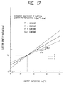
- Fig. 17 is a graph showing a temperature dependency of the ejection quantity.
- the ejection quantities of other recording heads are shown with curves b and c.
- control of ejection quantity according to the present invention can be carried out by using the relationships shown in Figs. 16 and 17.
- the pulse can be multi-pulses such as, for example, triple pulses and the control can be a main pulse PWM drive system for which the width of the main pulse is modulated with a single pulse.
- the drive is controlled so that the PWM value is primarily set from a difference ( ⁇ T) between the above-described target temperature and the head temperature.
- ⁇ T a difference between the above-described target temperature and the head temperature.
- temperature difference denotes the above ⁇ T
- preheat denotes the above P1
- interval denotes the above P2
- main denotes the above P3.
- setup time denotes a time until the above P1 actually rises after a recording instruction is entered. (This time is mainly an allowance time until the rise of the driver and is not a value which shares an principal factor of the present invention.)
- weight is a weight coefficient to be multiplied with the number of print dots to be detected to calculate the head temperature. In printing the same number of print dots, there will be a difference in the rise of head temperature between printing in the pulse width of 7 ⁇ s and printing in the pulse width of 4.5 ⁇ s. The above "weight” is used as means for compensating the difference of temperature rises along with modulation of the pulse width according to which PWM table is selected.
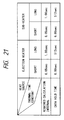
- Fig. 27 shows an interrupt routine for setting the PWM drive value and a sub-heater drive time for ejection. This interrupt routine occurs every 50m sec. The PWM value and the sub-heater drive time are always updated every 50m sec, regardless that the printing head is printing or idling and the drive of the sub-heater is necessary or unnecessary.
- the printing duty for 50m sec shortly before the interrupt is referred (S2010).
- the printing duty to be referred to in this case is represented by a value obtained by multiplying the number of dots for which ink has been actually ejected by a weight coefficient for each PWM value as described in (PWM control). From the duty for this 50m sec and the printing history for the past 0.8 seconds, the temperature rise ( ⁇ Tmh) of a group of components for which the heat source is the ejection heater and the time constants are of a short range is calculated (S2020).
- the drive duty of the sub-heater for 50m sec is referred to (S2030)
- the temperature rise ( ⁇ Tsh) of a group of components for which the heat source is the ejection heater and the time constants are of a short range is calculated from the drive duty of the sub-heater for 50m sec and the drive history of the sub-heater for 0.8 seconds (S2040).
- a target temperature is set from the target temperature table (S2060) and a difference ( ⁇ T) between the head temperature and the target temperature is obtained (S2070).
- a PWM value which is an optimum head drive condition in response to ⁇ T is set from the temperature difference ⁇ T, the PWM table and the sub-heater table (S2080).
- a sub-heater drive time which is an optimum head drive condition in response to the temperature difference ⁇ T is set (S2100) according to the selected sub-heater table (S2090). Up to the above, the interrupt routine is finished.
- Fig. 28 shows the main routine.
- the printing duty for the past one second is referred to (S3020).
- the printing duty is a value obtained by multiplying the number of dots for actual ejection by the weight coefficient for each PWM value as described in (PWM Control).
- a temperature rise ( ⁇ Tmb) of a group of components for which the heat source is the ejection heater and the time constants are of a long range is calculated from the printing history in the duty of one second and the past 512 seconds and stored as updated at a specified location of the memory (S3030) so that it can be easily referred to for the interrupt of every 50m sec.
- the drive duty of the sub-heater for one second is referred to (S3040), and a temperature rise ( ⁇ Tsb) of a group of components for which the heat source is the sub-heater and the time constants are of a long range is calculated from the printing history in the duty of one second and the past 512 seconds.
- ⁇ Tsb the temperature rise ⁇ Tsb calculated as above is stored as updated at a specified location of the memory so that it can be easily referred to for the interrupt of every 50m sec (S3050).
- Printing and driving of the sub-heater are carried out according to the PWM value and the sub-heater drive time which are updated upon each entry of the interrupt of 50m sec.
- PWM of double pulse and single pulse are used for controlling ejection quantity and head temperature; PWM of triple pulses or more pulses may be used.
- the scanning speed for a carriage may be controlled, or the scanning start timing for the carriage may be controlled.
- the main unit of a recording apparatus should identify various characteristics of a recording head. Moreover, in this embodiment, since a recording head 1 is in a replaceable fashion, the above mentioned head characteristics are measured without fail at head replacement. Items of measurement are the following four:
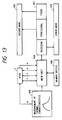
- Fig. 13 shows a schematic diagram of measurement of head characteristics. This embodiment shows that head characteristics measured by a main unit are the above mentioned four items.
- a represents the measurement of ejection heater characteristics
- b represents the measurement of Di sensor characteristics
- c represents ejection heater characteristics
- d represents sub-heater thermal characteristics.
- inputs and outputs such as energy application, the measurement of temperature, etc., between a main unit 40A and a head 1, and a decision 40C on individual head characteristics is made on the basis of the results of the measurement 40B. Then, a definition as provisional or fixed may be made.
- a record mode 40D is entered for becoming ready for recording.
- an error mode 40E is entered, and the main unit 40A indicates an error.
- Individual head characteristic values are stored in a memory device 40F. The stored values are used to determine whether a head has been replaced or the same head as that used previously is used.
- a dummy resistance 20E (Fig. 9) is measured.
- a drive voltage application time is variable in correspondence with a dispersion in the resistance value of the ejection heater for optimum drive.
- a PWM table as shown in Fig. 26 is provided for each ejection heater characteristic (head rank).
- diode sensor characteristics are measured.
- An ambient temperature is measured by a thermistor built in the main unit of a recording apparatus.
- a diode sensor reference output voltage and a temperature-output voltage characteristic (gradient value) at a reference temperature (for example, 25°C) is previously known.
- a diode sensor output voltage at the above mentioned ambient temperature is converted to that at the reference temperature (25°C), thereby measuring characteristics of a diode sensor by comparison with the diode sensor reference output voltage. Since the output of the diode sensor depends on a head temperature, characteristics of the diode sensor cannot be measured when a recording head is different in temperature from a main unit temperature or when sharp temperature changes exist. In such a case, it is needed to wait until the thermal stability is established.
- the recording head If, however, the recording head is considered as a new one, it may have been left in an environment whose temperature is extremely different from that of an environment in which the main unit is installed, accordingly, to measure its diode rank, a considerable waiting time is needed after the recording head is mounted on the main unit.
- the new recording head provides a large thermal time constant until it is adjusted to the temperature of the environment in which the main unit is installed, since the entire head has been adapted to the previous ambient temperature; it is noticeable if the entire recording head portion has a large thermal capacity.
- ink tanks and a recording head are integrated, its head temperature will not be easily stabilized since ink and ink tanks have a large thermal capacity.
- an air within a frame of the recording heads acts as a large thermal capacity, therefore, it becomes still harder to stabilize the head temperature; it may take approximately one hour until the temperature is stabilized.
- the diode rank is presumed by estimating the temperature of a recording head from changes of values during a fixed time observed on diode sensors of the recording head and a thermistor temperature in the main unit during the time.
- the main body of the recording apparatus has a calculation table for the sub-heater for temperature calculation.
- This calculation table contains temperature changes of the printing head at a constant interval of time (way of heat transmission as viewed from a Di sensor).
- the way of joining between members of a printing head, an ejection quantity, a dispersion in a main unit power supply for heater drive, etc. cause the contents of the calculation table to vary for each printing head.
- temperature changes are divided into three patterns for easy-to-accumulate-heat printing heads through hard-to-accumulate-heat heads, and corresponding three calculation tables mentioned above are provided.
- a center table 2 indicative of central conduction of heat for printing heads is provided between a large-temperature-change table 3 (easy to accumulate heat) and a small-temperature-change table 1 (hard to accumulate heat).
- Fig. 12 shows an increase/decrease of temperature for each thermal characteristic at application of an identical energy.
- a diagram a represents a central increase/decrease of temperature
- a diagram b represents an increase/decrease of temperature for the case of high increased temperatures due to large accumulation of heat
- a diagram c represents the one for the case of low increased temperatures due to small accumulation of heat.
- a measurement value will be greater than a threshold 2; hence, the large-temperature-change table 3 is selected as a calculation table.
- the small-temperature-change table 1 is selected on the assumption that a head is hard to accumulate heat.
- the center table 2 is selected on the assumption that a head is a standard printing head.
- thermal characteristics of an ejection heater are measured.
- the operation of measurement is identical to that for the above mentioned method for measuring sub-heater thermal characteristics, but what is driven is the ejection heater.
- measurement values of an ejection heater and a diode sensor are divided into ranks for management. This method allows the easy handling of measurement values for comparison with previous measurement values and for storing/saving in the main unit of a recording apparatus.
- Ejection heater characteristics are represented with a dummy resistance 20E.
- a dispersion of the dummy resistance 20E is 272.1 ⁇ ⁇ about 15%.
- a dispersion of resistance values is divided into 13 ranks. A center value is taken as rank 7, and the width of a resistance value within one rank is about 8 ⁇ , about 2.3 % of an overall dispersion. Division into finer ranks allows head rank setting at a higher precision, but requires a read circuit of a higher precision on the main unit side of the recording apparatus.
- the recording apparatus has read head ranks, when the read head ranks are written to memory members (EEPROM, NVRAM, etc.), the above mentioned numbers 1 to 13 are stored for each of four heads.
- Di sensor characteristics of a diode sensor
- characteristics of a diode sensor are also divided into ranks for similar reason.
- Di sensors there exists not so much a dispersion in a coefficient of proportion (hereinafter referred to as gradient) for temperature-output voltage (when used for head temperature management in this embodiment); however, offsets (dispersion of output values at the same temperature) disperse considerably among sensors.
- gradient coefficient of proportion
- offsets displacement of output values at the same temperature
- Fig. 4 illustrates Di sensor ranks. Taking temperature along the axis of abscissa and the output voltage of a Di sensor along the axis of ordinate, Fig. 4 diagrams center values of each rank. In actuality, a voltage value having a width is in contact with that of an adjacent rank for each rank. Assume that an output is 1.125 V when the Di sensor of a certain head is at 20°C (when a thermistor temperature is considered identical to a head temperature, a correction is made so that the thermistor temperature agrees with a Di sensor temperature).
- a gradient is substantially constant, and in this embodiment, the gradient is as follows: -5,0 [mV/°C] Hence, an output voltage converted to that at 25°C is 1.1 V.
- the output voltage value of a Di sensor is converted to that at an ambient temperature of 25°C by using a gradient value, and the converted value is compared with a previously prepared conversion table for determining a rank.
- Di sensors in this embodiment has the following dispersion of output voltage at 25°C. 1.1 ⁇ 0.05 [V] Hence, from the aforementioned gradient value of -5.0 mV/°C, a dispersion of ⁇ 10°C occurs at the same output voltage.
- a temperature dispersion in one rank is 2°C, and with 20 ranks set, the same is 1°C.
- the above mentioned number of ranks is determined at a precision required for head temperature management.
- the detection width for a divided voltage becomes accordingly narrower; hence, the precision of a detection circuit needs to be accordingly higher.
- ranks for ranked Di sensors are stored for each color head.
- a temperature Ts of the recording head is measured and stored first, on the assumption that the diode sensor rank is considered as a standard value (103C, 103F, 103G, and 103H). Second, a temperature T of the recording head is measured again after an elapse of a fixed time t (103D). At the same time, a room temperature T0 in the main unit is measured by a thermistor (103E).
- temperature values of the recording head converge to an ambient temperature (room temperature) at a certain time constant like exponential functions (Expression 1).
- the temperature to which the temperature values are converged can be obtained from Expression 2.
- T (Ts - T0) ⁇ exp (- t1 / tj) + T0
- the diode rank is determined so that T0 obtained from this expression matches the thermistor temperature. Since time constant tj is great compared to a head immediately after printing, t1 and A are set to 30 sec. and 0.94, respectively, in this embodiment.
- the above-described calculation table numbers are stored as rank values of these heaters.
- step S1010 Head ranks are measured in step S1010 first, and if they are not identical, it is determined that a different head is installed, in step S1020.
- the head characteristics are measured for all heads whether or not there are any temperature changes in the vicinity of Di sensors.
- step S1030 diode (Di) sensor ranks are presumed and then stored as provisional values.
- step S1040 If head ranks are determined to be identical in step S1020, it is checked that there are any changes in temperatures of the Di sensors, in step S1040. Since the Di sensors can sense temperature changes even if their rank values are not determined, it is determined whether the temperatures in the vicinity of the Di sensors are stable by checking a temperature variance within a fixed time.
- a presence of a change of 0.2°C or more in 10 sec. is defined as a temperature change. This is because a temperature change can be fully confirmed by a change in 10 sec. since a temperature change is large due to a smaller thermal time constant immediately after printing, contrary to the diode rank determination. If it is determined that a temperature change is present in step S1040, this condition is not suitable for the Di sensor rank measurement, therefore, the measurement (output voltage measurement) is omitted, and a previous Di sensor rank value is used in step S1060. At this time, the rank value is determined whether it is provisional or fixed. If the previous Di sensor rank is a fixed value in step S1050, the installed recording head is determined to be the same as one at the previous characteristics measurement, and the previous characteristics value is used.
- this provisional value is used in step S1070.
- the previous values can be also used for thermal characteristics of sub-heaters and ejection heaters or the previous central table value can be used as a provisional value, though thermal characteristics of sub-heaters and ejection heaters are measured again in this embodiment. In this case, temperature changes in the vicinity of the previous printing heads will not affect the measurement of the thermal characteristics of the sub-heaters and ejection heaters. The characteristics of the heads, however, must be measured again as soon as possible due to a use of the provisional value.
- the Di sensor ranks can be measured in a short time, therefore, they are measured in step S1080. If the measured values are the same as the previously-stored values when they are compared each other in step S1090, the Di sensor ranks are determined to be fixed and the heads are identical with the previous ones, and the previously-stored values are used for the thermal characteristics of the sub-heaters and ejection heaters in step S1060. If the measured values are not the same as the previous values in the comparison in step S1090, the Di sensor rank values are determined to be provisional and the heads are different from the previous ones, and then the thermal characteristics of the sub-heaters and ejection heaters are measured again in step S1100.
- a precise rank measurement can be achieved by determining whether the above rank measurement is performed according to a presence of any temperature changes of the Di sensors prior to the Di sensor rank measurement. Furthermore, the combination of the provisional and fixed characteristic values makes it possible to apply precise values to ranks even if the sensors are placed in unsuitable conditions for the Di sensor rank measurement due to a temperature change in the above. If the head ranks are identical with the previous ones and the Di sensor ranks are fixed values, the previous stored values can be used for respective head characteristics independently from temperature changes.
- the remeasurement of head characteristics is conducted.
- central characteristic values like provisional values, etc. are used to shorten the above mentioned start-up time for making the recording apparatus ready to use.
- the above mentioned remeasurement of head characteristics (hereinafter referred to as correction of head characteristics) is made while the recording apparatus is not used by a user, for deciding more accurate fixed values from head characteristic values used as provisional values, thereby improving the precision of head control.
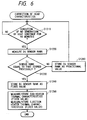
- a Di sensor rank is measured after no generation of heat has continued for 60 minutes at a recording head of the recording apparatus.
- This generation of heat is that when an ejection heater or a sub-heater is driven.
- this is interpreted as no generation of heat, and the measurement of a Di sensor rank is executed at step S1220 on the assumption that there is no change in temperature near a recording head.
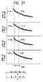
- the reason why this embodiment employs a time of no generation of heat of 60 minutes is, as shown in Figs.
- a measured Di sensor rank value is compared with a previously stored value, and if they are equal to each other, the measured Di sensor rank is stored as a fixed value at step S1240.
- sub-heater/ejection heater thermal characteristics are remeasured using the fixed value, for storing the measured thermal characteristics as final recording head characteristic values. If the above mentioned measured Di sensor rank is found unequal to that stored previously, the measured Di sensor rank is stored as a provisional value at step S1260, and then, a sequence of waiting for a 60-minute continuation of no generation of heat is again entered.
- Fig. 6 when a Di sensor rank is fixed once and sub-heater/ejection heater thermal characteristics are measured, the above mentioned correction of head characteristics is completed.
- a routine may be such that after fixing a Di sensor rank and then completing the measurement of sub-heater/ejection heater thermal characteristics, a return to the initial sequence of waiting for a 60-minute continuation of no generation of heat is made for repeating the operation of correction.
- the heads or heads are identical with the previous ones by setting an allowable range for the ranks which are the previous head characteristic values. For example, when the previous head characteristics are measured, the highest priority is given to reduction of a starting time for the recording apparatus so as to be usable, and the heads and ranks (sub-heaters and ejection heaters of Di sensors) are determined to be identical with the previous ones only if the difference is within ⁇ 2 ranks. Accordingly, the heads can be determined to be identical with the previous ones even if there is a variation in measurements by setting a criterion with some allowance, and the past stored values are used, so that the starting time can be reduced.
- the highest priority is given to preciseness, and the allowance for identical ranks is set to a range within ⁇ 1 rank. Narrowing the allowance range in this way makes it possible to set more precise rank values of the characteristics when they are determined to be fixed. Allowance ranges for precision used like this are not limited to the above values, if necessary.
- characteristics of the thermal sensors of a new recording head are presumed by detecting that the new recording head is installed, therefore, the characteristics of the thermal sensors can be obtained precisely and in a short time.
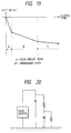
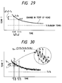
- a temperature of a recording head has noise elements as shown in Fig. 30 also when printing is not performed. Accordingly, the noise elements are removed by measuring an average temperature in approx. one sec. at 50 ms intervals when T s and T are measured. This makes it possible to shorten sampling intervals T s and T and to improve the precision of diode rank values at the same sampling intervals.
- a recording head consists of a plurality of heads integrated in a frame and it is considered as a new head, all the heads have been placed in a common environment.
- An object of this embodiment is to reduce an error of a presumed diode rank when an LED or the like is set in the 1st embodiment.
- the diode rank presumption in the 1st embodiment is performed when a plug of the main unit is put in an outlet. At this time, a user has not turned on a soft power switch yet, therefore, there is no indication with the LED and the main unit looks as if it should not be started.
- the main unit is practically under an operation of the diode rank presumption and temperatures of the recording heads are being measured. Unless the soft power switch is turned on afterward, the diode rank assumption will be completed to the end. In this embodiment, however, the LED is lit to indicate the operation when the soft power switch is turned on, and if the temperature presumption of the recording heads is not completed, a diode rank presumption is started anew.
- the downward movement of the temperature measurement due to lighting the LED is approx. 0.5°C which is a change level having no difficulty for a normal control.
- a presumed temperature has an error of 8.3°C when ⁇ T is 0.5°C in this embodiment since A becomes 0.94. If the driving control is based on a presumed temperature having such an extreme error, it is difficult to assure stable ink ejection or ejection quantity.
- FIG. 2 there is shown a general structure of this embodiment. It is different from Fig. 1 illustrating the structure of the 1st embodiment in respect of LED 104I connected to power supply 104H.
- the temperature change due to the LED flickering is removed by measuring an average value of the recording head temperature in units of a time interval which is a half of an LED flickering period as shown in Fig. 33.
- An average of the temperatures in one LED flickering period is measured as shown in Fig. 33 in this embodiment.
- the present invention provides precise and short-time measurement of characteristics of the temperature sensors by detecting that a new recording head is installed and presuming the characteristics of the temperature sensors of the recording head, so that it makes it possible to improve an image quality of the ink jet recording apparatus and to increase the throughput at a lower cost.
- the present invention is particularly suitably usable in an ink jet recording head and recording-apparatus wherein thermal energy by an electrothermal transducer, laser beam or the like is used to cause a change of state of the ink to eject or discharge the ink. This is because the high density of the picture elements and the high resolution of the recording are possible.
- the typical structure and the operational principle are preferably the ones disclosed in U.S. Patent Nos. 4,723,129 and 4,740,796.
- the principle and structure are applicable to a so-called on-demand type recording system and a continuous type recording system.
- it is suitable for the on-demand type because the principle is such that at least one driving signal is applied to an electrothermal transducer disposed on a liquid (ink) retaining sheet or liquid passage, the driving signal being enough to provide such a quick temperature rise beyond a departure from nucleation boiling point, by which the thermal energy is provided by the electrothermal transducer to produce film boiling on the heating portion of the recording head, whereby a bubble can be formed in the liquid (ink) corresponding to each of the driving signals.
- the liquid (ink) is ejected through an ejection outlet to produce at least one droplet.
- the driving signal is preferably in the form of a pulse, because the development and contraction of the bubble can be effected instantaneously, and therefore, the liquid (ink) is ejected with quick response.
- the driving signal in the form of the pulse is preferably such as disclosed in U.S. Patents Nos. 4,463,359 and 4,345,262.
- the temperature increasing rate of the heating surface is preferably such as disclosed in U.S. Patent No. 4,313,124.
- the structure of the recording head may be as shown in U.S. Patent Nos. 4,558,333 and 4,459,600 wherein the heating portion is disclosed at a bent portion, as well as the structure of the combination of the ejection outlet, liquid passage and the electrothermal transducer as disclosed in the above-mentioned patents.
- the present invention is applicable to the structure disclosed in Japanese Laid-Open Patent Application No. 59-123670 wherein a common slit is used as the ejection outlet for plural electrothermal transducers, and to the structure disclosed in Japanese Laid-Open Patent Application No. 59-138461 wherein an opening for absorbing pressure wave of the thermal energy is formed corresponding to the ejecting portion. This is because the present invention is effective to perform the recording operation with certainty and at high efficiency irrespective of the type of the recording head.
- the present invention is effectively applicable to a so-called full-line type recording head having a length corresponding to the maximum recording width.
- a recording head may comprise a single recording head and plural recording head combined to cover the maximum width.
- the present invention is applicable to a serial type recording head wherein the recording head is fixed on the main assembly, to a replaceable chip type recording head which is connected electrically with the main apparatus and can be supplied with the ink when it is mounted in the main assembly, or to a cartridge type recording head having an integral ink container.
- the provisions of the recovery means and/or the auxiliary means for the preliminary operation are preferable, because they can further stabilize the effects of the present invention.
- preliminary heating means which may be the electrothermal transducer, an additional heating element or a combination thereof.
- means for effecting preliminary ejection (not for the recording operation) can stabilize the recording operation.
- the recording head mountable may be a single corresponding to a single color ink, or may be plural corresponding to the plurality of ink materials having different recording color or density.
- the present invention is effectively applicable to an apparatus having at least one of a monochromatic mode mainly with black, a multi-color mode with different color ink materials and/or a full-color mode using the mixture of the colors, which may be an integrally formed recording unit or a combination of plural recording heads.
- the ink has been liquid. It may be, however, an ink material which is solidified below the room temperature but liquefied at the room temperature. Since the ink is controlled within the temperature not lower than 30°C and not higher than 70°C to stabilize the viscosity of the ink to provide the stabilized ejection in usual recording apparatus of this type, the ink may be such that it is liquid within the temperature range when the recording signal is the present invention is applicable to other types of ink. In one of them, the temperature rise due to the thermal energy is positively prevented by consuming it for the state change of the ink from the solid state to the liquid state. Another ink material is solidified when it is left, to prevent the evaporation of the ink.
- the ink is liquefied, and the liquefied ink may be ejected.
- Another ink material may start to be solidified at the time when it reaches the recording material.
- the present invention is also applicable to such an ink material as is liquefied by the application of the thermal energy.
- Such an ink material may be retained as a liquid or solid material in through holes or recesses formed in a porous sheet as disclosed in Japanese Laid-Open Patent Application No. 54-56847 and Japanese Laid-Open Patent Application No. 60-71260. The sheet is faced to the electrothermal transducers. The most effective one for the ink materials described above is the film boiling system.
- the ink jet recording apparatus may be used as an output terminal of an information processing apparatus such as computer or the like, as a copying apparatus combined with an image reader or the like, or as a facsimile machine having information sending and receiving functions.
Landscapes
- Engineering & Computer Science (AREA)
- Quality & Reliability (AREA)
- Ink Jet (AREA)
- Particle Formation And Scattering Control In Inkjet Printers (AREA)
- Heating, Cooling, Or Curing Plastics Or The Like In General (AREA)
- Electronic Switches (AREA)
- Heat Sensitive Colour Forming Recording (AREA)
- Thermal Transfer Or Thermal Recording In General (AREA)
Claims (35)
- Appareil d'enregistrement destiné à enregistrer une image sur un support d'enregistrement, en utilisant une tête (1) d'enregistrement, pouvant se monter sur l'appareil, ladite tête (1) d'enregistrement comprenant un moyen destiné à engendrer de l'énergie thermique (1b) pour enregistrement, et un capteur (20c) de température destiné à sortir une valeur de sortie correspondant à une température détectée, ledit appareil comprenant :un moyen (3) de montage destiné à monter de façon amovible une tête (1) d'enregistrement ;un moyen (103b, 104b, 60) de prédiction, pouvant être mis en oeuvre après le montage de la tête (1) d'enregistrement sur ledit moyen (3) de montage, pour prédire des caractéristiques du capteur (20c) de température de ladite tête (1) d'enregistrement, en se basant sur un changement, en fonction du temps, de la valeur de sortie dudit capteur de température ; etun moyen (60) de correction destiné à corriger une valeur basée sur la valeur de sortie dudit capteur (20c) de température en traitant des données incluant les caractéristiques prédites par ledit moyen de prédiction,
l'appareil étant ainsi apte à commander l'enregistrement par ladite tête (1) d'enregistrement en fonction de la valeur dudit capteur (20c) de température telle qu'elle a été corrigée par ledit moyen de correction. - Appareil selon la revendication 1, dans lequel ledit moyen de correction corrige la valeur de sortie dudit capteur (20C) de température en traitant, au moins initialement, lesdites caractéristiques prédites.
- Appareil selon la revendication 1, comprenant en outre un moyen de détection destiné à détecter des caractéristiques dudit capteur de température de manière précise.
- Appareil selon la revendication 3, dans lequel ledit moyen de correction corrige la température captée dudit capteur de température en utilisant des caractéristiques détectées après que les caractéristiques dudit capteur de température ont été prédites par ledit moyen de prédiction.
- Appareil selon la revendication 1, comprenant en outre un capteur (103E) d'environnement destiné à détecter une température ambiante dudit appareil d' enregistrement.
- Appareil selon la revendication 5, dans lequel ledit moyen de prédiction prédit des caractéristiques dudit capteur (20C) de température de tête d'enregistrement sur la base de changements de température de ladite tête (1) d'enregistrement détectés par ledit capteur (20C) de température dans un temps fixé et de la température ambiante détectée par ledit capteur (103E) d'ambiance.
- Appareil selon la revendication 6, dans lequel ladite tête d'enregistrement est constituée d'une pluralité d'éléments (2bk, 2c, 2m, 2y) de tête qui sont intégrés.
- Appareil selon la revendication 7, dans lequel un capteur respectif de température de tête d'enregistrement est disposé sur chaque élément (2bk, 2c, 2m, 2y) de tête individuellement, et dans lequel ledit moyen de prédiction utilise, comme changement de température de ladite tête d'enregistrement, une valeur moyenne des changements de température dans lesdits éléments de tête, détectés par ladite pluralité de capteurs de température de tête d'enregistrement.
- Appareil selon la revendication 7, dans lequel lesdits éléments respectifs (2bk, 2c, 2m, 2y) de tête effectuent l'enregistrement avec des couleurs différentes les unes des autres.
- Appareil selon la revendication 6, dans lequel ledit moyen de prédiction exécute de nouveau l'opération de détection d'un changement de température de ladite tête d'enregistrement lorsqu'un état de température dudit appareil d'enregistrement change pendant la détection du changement de température de ladite tête d'enregistrement.
- Appareil selon la revendication 6, comprenant en outre une partie (104I) d'indication destinée à indiquer un état de température dudit appareil d'enregistrement.
- Appareil selon la revendication 11, dans lequel ladite partie (104I) d'indication clignote pendant le fonctionnement dudit moyen de prédiction.
- Appareil selon la revendication 12, dans lequel ledit moyen de prédiction utilise, comme changement de température de ladite tête d'enregistrement, une valeur moyenne d'un changement de température de ladite tête (1) d'enregistrement dans une période dont l'unité est la moitié de la période de clignotement dudit élément (104I) d'indication.
- Appareil selon la revendication 1, dans lequel ladite tête (1) d'enregistrement éjecte de l'encre en utilisant de l'énergie thermique.
- Appareil selon la revendication 1, dans lequel ladite tête (1) d'enregistrement possède une aptitude à enregistrer avec plusieurs couleurs.
- Appareil selon la revendication 1, comprenant en outre un chariot (3) sur lequel est montée ladite tête (1) d'enregistrement.
- Appareil selon la revendication 1, comprenant en outre un moyen (11) d'avancement destiné à faire avancer un support (P) d'enregistrement sur lequel ladite tête (1) d'enregistrement enregistre des images.
- Appareil selon la revendication 1, dans lequel ledit appareil (1) d'enregistrement est appliqué à une machine à copier.
- Appareil selon la revendication 1, dans lequel ledit appareil (1) d'enregistrement est appliqué à un télécopieur.
- Appareil selon la revendication 1, dans lequel ledit appareil (1) d'enregistrement est appliqué à un terminal d'ordinateur.
- Procédé d'enregistrement destiné à enregistrer, à l'aide d'une tête d'enregistrement montée dans un appareil d'enregistrement, pour enregistrer des images, ladite tête (1) d'enregistrement comprenant un moyen destiné à engendrer de l'énergie thermique (1b), ledit procédé comprenant les étapes :de montage, de façon amovible, d'une tête (1) d'enregistrement ;de détection d'une valeur de sortie d'un capteur (20c) de température sur ladite tête d'enregistrement ;de prédiction de caractéristiques dudit capteur (20C) de température en se basant sur un changement, en fonction du temps, de la valeur de sortie ; etde correction d'une valeur basée sur la valeur de sortie dudit capteur (20C) de température en traitant des données incluant les caractéristiques prédites.
- Procédé selon la revendication 21, dans lequel, dans ladite étape de correction, on corrige la valeur de sortie dudit capteur (20C) de température en traitant, au moins initialement, lesdites caractéristiques prédites.
- Procédé selon la revendication 21, comprenant en outre l'étape de détection de caractéristiques dudit capteur de température, de manière précise.
- Procédé selon la revendication 23, dans lequel, dans ladite étape de correction, on corrige les températures captées dudit capteur de température en utilisant des caractéristiques détectées, dudit capteur de température, après que les caractéristiques du capteur de température ont été prédites dans ladite étape de prédiction.
- Procédé selon la revendication 24, comprenant en outre les étapes de détection d'une température ambiante dudit appareil d'enregistrement.
- Procédé selon la revendication 25, dans lequel, dans ladite étape de prédiction, on prédit les caractéristiques du capteur de température sur la base d'un changement de température de ladite tête d'enregistrement détecté par ledit capteur de température dans un temps fixé et d'une température ambiante détectée.
- Procédé selon la revendication 26, dans lequel ladite tête d'enregistrement est constituée d'une pluralité d'éléments de tête qui sont intégrés.
- Procédé selon la revendication 27, dans lequel un capteur de température respectif est agencé sur chaque élément de tête correspondant, et le changement de température de ladite tête d'enregistrement, dans ladite étape de prédiction, est une valeur moyenne de changements de température desdits éléments de tête, détectés par ladite pluralité de capteurs de température.
- Procédé selon la revendication 27, dans lequel lesdits éléments de tête enregistrent des images avec leurs couleurs respectives, différentes les unes des autres.
- Procédé selon la revendication 26, dans lequel, dans l'étape de prédiction, on exécute de nouveau l'opération de prédiction pour un changement de température de ladite tête d'enregistrement lorsqu'un état de température dudit appareil d'enregistrement change pendant la détection du changement de température de ladite tête d'enregistrement.
- Procédé selon la revendication 26, comprenant en outre l'étape d'indication d'un état de température dudit appareil d'enregistrement.
- Procédé selon la revendication 31, dans lequel, dans ladite étape d'indication, un élément d'indication clignote pendant l'exécution de ladite étape de prédiction.
- Procédé selon la revendication 32, dans lequel, dans ladite étape de prédiction, un changement de température de ladite tête d'enregistrement à utiliser est une valeur moyenne d'un changement de température de ladite tête d'enregistrement dans une période dont l'unité est la moitié de la période de clignotement dudit élément d'indication.
- Procédé selon la revendication 21, dans lequel ladite tête d'enregistrement éjecte de l'encre en utilisant de l'énergie thermique.
- Procédé selon la revendication 21, dans lequel ladite tête d'enregistrement possède une aptitude à enregistrer avec plusieurs couleurs.
Applications Claiming Priority (2)
| Application Number | Priority Date | Filing Date | Title |
|---|---|---|---|
| JP12639593A JP3235753B2 (ja) | 1993-05-27 | 1993-05-27 | インクジェット記録装置及び同装置における温度センサからの出力に応じた信号を補正する補正方法 |
| JP126395/93 | 1993-05-27 |
Publications (3)
| Publication Number | Publication Date |
|---|---|
| EP0626263A2 EP0626263A2 (fr) | 1994-11-30 |
| EP0626263A3 EP0626263A3 (fr) | 1995-05-10 |
| EP0626263B1 true EP0626263B1 (fr) | 1999-04-21 |
Family
ID=14934088
Family Applications (1)
| Application Number | Title | Priority Date | Filing Date |
|---|---|---|---|
| EP94303813A Expired - Lifetime EP0626263B1 (fr) | 1993-05-27 | 1994-05-26 | Méthode et appareil d'enregistrement thermique |
Country Status (5)
| Country | Link |
|---|---|
| US (1) | US6024430A (fr) |
| EP (1) | EP0626263B1 (fr) |
| JP (1) | JP3235753B2 (fr) |
| AT (1) | ATE179120T1 (fr) |
| DE (1) | DE69417947T2 (fr) |
Families Citing this family (17)
| Publication number | Priority date | Publication date | Assignee | Title |
|---|---|---|---|---|
| JP3143549B2 (ja) * | 1993-09-08 | 2001-03-07 | キヤノン株式会社 | 熱記録ヘッド用基体、該基体を用いたインクジェット記録ヘッド、インクジェットカートリッジ、インクジェット記録装置、及び記録ヘッドの駆動方法 |
| US6951378B1 (en) * | 1998-05-04 | 2005-10-04 | Canon Kabushiki Kaisha | Print control based on print head temperature |
| US7339690B2 (en) * | 1999-07-14 | 2008-03-04 | Fargo Electronics, Inc. | Identification card printer with client/server |
| DE60039627D1 (de) * | 1999-12-15 | 2008-09-04 | Fargo Electronics Inc | Vorrichtung zum personalizieren einer id karte mit web browser |
| US6464318B2 (en) * | 2000-06-29 | 2002-10-15 | Brother Kogyo Kabushiki Kaisha | Recording device capable of accurately detecting temperature of recording head |
| JP3880411B2 (ja) * | 2001-01-31 | 2007-02-14 | キヤノン株式会社 | 記録装置 |
| JP2005219391A (ja) * | 2004-02-06 | 2005-08-18 | Canon Inc | インクジェット記録装置 |
| US7097280B2 (en) * | 2004-02-12 | 2006-08-29 | Lexmark International, Inc. | Printheads having improved heater chip construction |
| US20050179739A1 (en) * | 2004-02-17 | 2005-08-18 | Fuji Xerox Co., Ltd. | Methods and apparatus for thermal fluid jet drop volume control using variable length pre-pulses |
| US7572051B2 (en) * | 2004-11-15 | 2009-08-11 | Palo Alto Research Center Incorporated | Method and apparatus for calibrating a thermistor |
| JP4208869B2 (ja) | 2005-09-09 | 2009-01-14 | キヤノン株式会社 | インクジェット記録装置およびインクジェット記録方法 |
| JP2010214866A (ja) | 2009-03-18 | 2010-09-30 | Canon Inc | 記録装置および記録制御方法 |
| US8523312B2 (en) | 2010-11-08 | 2013-09-03 | Seagate Technology Llc | Detection system using heating element temperature oscillations |
| KR101496162B1 (ko) | 2010-11-17 | 2015-02-27 | 시게이트 테크놀로지 엘엘씨 | 헤드-매체 간격 및 접촉 검출을 위한 다수의 저항 온도 센서들을 갖는 헤드 트랜스듀서 |
| US10166763B2 (en) | 2014-06-18 | 2019-01-01 | Canon Kabushiki Kaisha | Printing apparatus, printing method and storage medium |
| US9409390B1 (en) | 2015-03-06 | 2016-08-09 | Canon Kabushiki Kaisha | Printing apparatus and control method therefor |
| CN112041172B (zh) * | 2018-08-30 | 2022-06-10 | 惠普发展公司,有限责任合伙企业 | 基于热的液滴检测 |
Family Cites Families (19)
| Publication number | Priority date | Publication date | Assignee | Title |
|---|---|---|---|---|
| US3880006A (en) * | 1972-08-07 | 1975-04-29 | Stow Lab Inc | Electronic temperature sensing system |
| CA1127227A (fr) * | 1977-10-03 | 1982-07-06 | Ichiro Endo | Procede d'enregistrement a jet liquide et appareil d'enregistrement |
| JPS5936879B2 (ja) * | 1977-10-14 | 1984-09-06 | キヤノン株式会社 | 熱転写記録用媒体 |
| US4330787A (en) * | 1978-10-31 | 1982-05-18 | Canon Kabushiki Kaisha | Liquid jet recording device |
| US4345262A (en) * | 1979-02-19 | 1982-08-17 | Canon Kabushiki Kaisha | Ink jet recording method |
| US4463359A (en) * | 1979-04-02 | 1984-07-31 | Canon Kabushiki Kaisha | Droplet generating method and apparatus thereof |
| US4313124A (en) * | 1979-05-18 | 1982-01-26 | Canon Kabushiki Kaisha | Liquid jet recording process and liquid jet recording head |
| US4558333A (en) * | 1981-07-09 | 1985-12-10 | Canon Kabushiki Kaisha | Liquid jet recording head |
| JPS59123670A (ja) * | 1982-12-28 | 1984-07-17 | Canon Inc | インクジエツトヘツド |
| JPS59138461A (ja) * | 1983-01-28 | 1984-08-08 | Canon Inc | 液体噴射記録装置 |
| JPS6071260A (ja) * | 1983-09-28 | 1985-04-23 | Erumu:Kk | 記録装置 |
| KR910007684A (ko) * | 1989-10-03 | 1991-05-30 | 야마무라 가쯔미 | 서멀프린터의 구동 제어 장치 |
| DE69110523T2 (de) * | 1990-04-09 | 1995-11-30 | Seiko Instr Inc | Ansteuerverfahren für ein thermisches Druckelement. |
| EP0481625B1 (fr) * | 1990-10-04 | 1996-12-11 | Canon Kabushiki Kaisha | Appareil d'image d'enregistrement pour enregister utilisant une tête d'enregistrement |
| JP2915583B2 (ja) * | 1991-01-14 | 1999-07-05 | キヤノン株式会社 | 画像記録装置 |
| JP2974487B2 (ja) * | 1991-03-20 | 1999-11-10 | キヤノン株式会社 | 記録装置 |
| JPH0531918A (ja) * | 1991-08-02 | 1993-02-09 | Canon Inc | インクジエツト記録装置 |
| JP3244724B2 (ja) * | 1991-08-01 | 2002-01-07 | キヤノン株式会社 | インクジェット記録装置 |
| CA2074906C (fr) * | 1991-08-01 | 2000-09-12 | Hiromitsu Hirabayashi | Appareil d'enregistrement a jet d'encre a fonction de controle de la temperature |
-
1993
- 1993-05-27 JP JP12639593A patent/JP3235753B2/ja not_active Expired - Lifetime
-
1994
- 1994-05-26 AT AT94303813T patent/ATE179120T1/de not_active IP Right Cessation
- 1994-05-26 DE DE69417947T patent/DE69417947T2/de not_active Expired - Lifetime
- 1994-05-26 EP EP94303813A patent/EP0626263B1/fr not_active Expired - Lifetime
-
1997
- 1997-03-10 US US08/813,303 patent/US6024430A/en not_active Expired - Lifetime
Also Published As
| Publication number | Publication date |
|---|---|
| ATE179120T1 (de) | 1999-05-15 |
| JP3235753B2 (ja) | 2001-12-04 |
| DE69417947T2 (de) | 1999-09-30 |
| US6024430A (en) | 2000-02-15 |
| JPH06336025A (ja) | 1994-12-06 |
| EP0626263A3 (fr) | 1995-05-10 |
| DE69417947D1 (de) | 1999-05-27 |
| EP0626263A2 (fr) | 1994-11-30 |
Similar Documents
| Publication | Publication Date | Title |
|---|---|---|
| EP0626266B1 (fr) | Appareil d'enregistrement commandé par les caractéristiques de la tête et méthode d'enregistrement | |
| EP0924084B1 (fr) | Appareil d'enregistrement à jet d'encre contrôlé par température presumée et méthode de contrôle associée | |
| EP0626263B1 (fr) | Méthode et appareil d'enregistrement thermique | |
| US5880751A (en) | Ink jet recording apparatus and ink droplet amount ejection control method therefor | |
| US5576745A (en) | Recording apparatus having thermal head and recording method | |
| EP0838333B1 (fr) | Appareil d'enregistrement à jet d'encre avec contrôle de la température | |
| US5736995A (en) | Temperature control of thermal inkjet printheads by using synchronous non-nucleating pulses | |
| US6116710A (en) | Ink jet recording method and apparatus using thermal energy | |
| EP0650837B1 (fr) | Schéma de gestion de l'énergie pour une imprimante par jet d'encre | |
| US6652058B2 (en) | Recording apparatus and recording control method, and ink jet recording method and apparatus | |
| US20030142159A1 (en) | Estimating local ejection chamber temperature to improve printhead performance | |
| JP3372821B2 (ja) | インクジェット装置、該装置用インクジェットヘッドの温度推定方法および制御方法 | |
| JP3337912B2 (ja) | インクジェットヘッドの駆動方法及びこれを実行するインクジェット装置 | |
| JPH07125216A (ja) | インクジェット装置および該装置用インクジェットヘッドの制御方法 | |
| JPH05220963A (ja) | インクジェット記録ヘッドの吐出制御方法 | |
| JP3428690B2 (ja) | インクジェット記録装置 | |
| US6276776B1 (en) | Ink-jet printer and temperature control method of recording head | |
| JP3313751B2 (ja) | インクジェット記録ヘッドの吐出制御方法 | |
| JPH0752388A (ja) | インクジェット記録装置 | |
| EP0650836B1 (fr) | Réglage de la température pour têtes d'enregistrement thermique à jet d'encre au moyen d'impulsions de non-nucléation synchronisées | |
| JPH06336022A (ja) | 記録ヘッド認識方法とこれを実施する記録装置 | |
| EP0925927B1 (fr) | Dispositif d'enregistrement à jet d'encre et procédé pour son entraînement | |
| JP3190184B2 (ja) | 記録装置及び記録装置の補正方法 | |
| JP7790922B2 (ja) | 記録装置及び制御方法 | |
| JP2752467B2 (ja) | 記録装置 |
Legal Events
| Date | Code | Title | Description |
|---|---|---|---|
| PUAI | Public reference made under article 153(3) epc to a published international application that has entered the european phase |
Free format text: ORIGINAL CODE: 0009012 |
|
| AK | Designated contracting states |
Kind code of ref document: A2 Designated state(s): AT BE CH DE DK ES FR GB GR IE IT LI LU NL PT SE |
|
| PUAL | Search report despatched |
Free format text: ORIGINAL CODE: 0009013 |
|
| AK | Designated contracting states |
Kind code of ref document: A3 Designated state(s): AT BE CH DE DK ES FR GB GR IE IT LI LU NL PT SE |
|
| 17P | Request for examination filed |
Effective date: 19950925 |
|
| 17Q | First examination report despatched |
Effective date: 19961001 |
|
| GRAG | Despatch of communication of intention to grant |
Free format text: ORIGINAL CODE: EPIDOS AGRA |
|
| GRAG | Despatch of communication of intention to grant |
Free format text: ORIGINAL CODE: EPIDOS AGRA |
|
| GRAH | Despatch of communication of intention to grant a patent |
Free format text: ORIGINAL CODE: EPIDOS IGRA |
|
| GRAH | Despatch of communication of intention to grant a patent |
Free format text: ORIGINAL CODE: EPIDOS IGRA |
|
| GRAA | (expected) grant |
Free format text: ORIGINAL CODE: 0009210 |
|
| AK | Designated contracting states |
Kind code of ref document: B1 Designated state(s): AT BE CH DE DK ES FR GB GR IE IT LI LU NL PT SE |
|
| PG25 | Lapsed in a contracting state [announced via postgrant information from national office to epo] |
Ref country code: SE Free format text: THE PATENT HAS BEEN ANNULLED BY A DECISION OF A NATIONAL AUTHORITY Effective date: 19990421 Ref country code: NL Free format text: LAPSE BECAUSE OF FAILURE TO SUBMIT A TRANSLATION OF THE DESCRIPTION OR TO PAY THE FEE WITHIN THE PRESCRIBED TIME-LIMIT Effective date: 19990421 Ref country code: LI Free format text: LAPSE BECAUSE OF FAILURE TO SUBMIT A TRANSLATION OF THE DESCRIPTION OR TO PAY THE FEE WITHIN THE PRESCRIBED TIME-LIMIT Effective date: 19990421 Ref country code: GR Free format text: LAPSE BECAUSE OF NON-PAYMENT OF DUE FEES Effective date: 19990421 Ref country code: ES Free format text: THE PATENT HAS BEEN ANNULLED BY A DECISION OF A NATIONAL AUTHORITY Effective date: 19990421 Ref country code: CH Free format text: LAPSE BECAUSE OF FAILURE TO SUBMIT A TRANSLATION OF THE DESCRIPTION OR TO PAY THE FEE WITHIN THE PRESCRIBED TIME-LIMIT Effective date: 19990421 Ref country code: BE Free format text: LAPSE BECAUSE OF FAILURE TO SUBMIT A TRANSLATION OF THE DESCRIPTION OR TO PAY THE FEE WITHIN THE PRESCRIBED TIME-LIMIT Effective date: 19990421 Ref country code: AT Free format text: LAPSE BECAUSE OF FAILURE TO SUBMIT A TRANSLATION OF THE DESCRIPTION OR TO PAY THE FEE WITHIN THE PRESCRIBED TIME-LIMIT Effective date: 19990421 |
|
| REF | Corresponds to: |
Ref document number: 179120 Country of ref document: AT Date of ref document: 19990515 Kind code of ref document: T |
|
| REG | Reference to a national code |
Ref country code: CH Ref legal event code: EP |
|
| REG | Reference to a national code |
Ref country code: IE Ref legal event code: FG4D |
|
| PG25 | Lapsed in a contracting state [announced via postgrant information from national office to epo] |
Ref country code: LU Free format text: LAPSE BECAUSE OF NON-PAYMENT OF DUE FEES Effective date: 19990526 |
|
| REF | Corresponds to: |
Ref document number: 69417947 Country of ref document: DE Date of ref document: 19990527 |
|
| ET | Fr: translation filed | ||
| PG25 | Lapsed in a contracting state [announced via postgrant information from national office to epo] |
Ref country code: IE Free format text: LAPSE BECAUSE OF NON-PAYMENT OF DUE FEES Effective date: 19990621 |
|
| PG25 | Lapsed in a contracting state [announced via postgrant information from national office to epo] |
Ref country code: DK Free format text: LAPSE BECAUSE OF FAILURE TO SUBMIT A TRANSLATION OF THE DESCRIPTION OR TO PAY THE FEE WITHIN THE PRESCRIBED TIME-LIMIT Effective date: 19990721 |
|
| PG25 | Lapsed in a contracting state [announced via postgrant information from national office to epo] |
Ref country code: PT Free format text: LAPSE BECAUSE OF FAILURE TO SUBMIT A TRANSLATION OF THE DESCRIPTION OR TO PAY THE FEE WITHIN THE PRESCRIBED TIME-LIMIT Effective date: 19990722 |
|
| REG | Reference to a national code |
Ref country code: CH Ref legal event code: PL |
|
| PLBE | No opposition filed within time limit |
Free format text: ORIGINAL CODE: 0009261 |
|
| STAA | Information on the status of an ep patent application or granted ep patent |
Free format text: STATUS: NO OPPOSITION FILED WITHIN TIME LIMIT |
|
| 26N | No opposition filed | ||
| REG | Reference to a national code |
Ref country code: IE Ref legal event code: MM4A |
|
| REG | Reference to a national code |
Ref country code: GB Ref legal event code: IF02 |
|
| PGFP | Annual fee paid to national office [announced via postgrant information from national office to epo] |
Ref country code: IT Payment date: 20090515 Year of fee payment: 16 Ref country code: FR Payment date: 20090520 Year of fee payment: 16 |
|
| REG | Reference to a national code |
Ref country code: FR Ref legal event code: ST Effective date: 20110131 |
|
| PG25 | Lapsed in a contracting state [announced via postgrant information from national office to epo] |
Ref country code: IT Free format text: LAPSE BECAUSE OF NON-PAYMENT OF DUE FEES Effective date: 20100526 |
|
| PG25 | Lapsed in a contracting state [announced via postgrant information from national office to epo] |
Ref country code: FR Free format text: LAPSE BECAUSE OF NON-PAYMENT OF DUE FEES Effective date: 20100531 |
|
| PGFP | Annual fee paid to national office [announced via postgrant information from national office to epo] |
Ref country code: DE Payment date: 20120531 Year of fee payment: 19 |
|
| PGFP | Annual fee paid to national office [announced via postgrant information from national office to epo] |
Ref country code: GB Payment date: 20120517 Year of fee payment: 19 |
|
| GBPC | Gb: european patent ceased through non-payment of renewal fee |
Effective date: 20130526 |
|
| PG25 | Lapsed in a contracting state [announced via postgrant information from national office to epo] |
Ref country code: DE Free format text: LAPSE BECAUSE OF NON-PAYMENT OF DUE FEES Effective date: 20131203 |
|
| REG | Reference to a national code |
Ref country code: DE Ref legal event code: R119 Ref document number: 69417947 Country of ref document: DE Effective date: 20131203 |
|
| PG25 | Lapsed in a contracting state [announced via postgrant information from national office to epo] |
Ref country code: GB Free format text: LAPSE BECAUSE OF NON-PAYMENT OF DUE FEES Effective date: 20130526 |