EP0626268A2 - Drucker mit abnehmbarer Druckeinheit - Google Patents
Drucker mit abnehmbarer Druckeinheit Download PDFInfo
- Publication number
- EP0626268A2 EP0626268A2 EP94303801A EP94303801A EP0626268A2 EP 0626268 A2 EP0626268 A2 EP 0626268A2 EP 94303801 A EP94303801 A EP 94303801A EP 94303801 A EP94303801 A EP 94303801A EP 0626268 A2 EP0626268 A2 EP 0626268A2
- Authority
- EP
- European Patent Office
- Prior art keywords
- unit
- print unit
- printer
- thermal
- Prior art date
- Legal status (The legal status is an assumption and is not a legal conclusion. Google has not performed a legal analysis and makes no representation as to the accuracy of the status listed.)
- Withdrawn
Links
Images

Classifications
-
- B—PERFORMING OPERATIONS; TRANSPORTING
- B41—PRINTING; LINING MACHINES; TYPEWRITERS; STAMPS
- B41J—TYPEWRITERS; SELECTIVE PRINTING MECHANISMS, i.e. MECHANISMS PRINTING OTHERWISE THAN FROM A FORME; CORRECTION OF TYPOGRAPHICAL ERRORS
- B41J2/00—Typewriters or selective printing mechanisms characterised by the printing or marking process for which they are designed
- B41J2/315—Typewriters or selective printing mechanisms characterised by the printing or marking process for which they are designed characterised by selective application of heat to a heat sensitive printing or impression-transfer material
- B41J2/32—Typewriters or selective printing mechanisms characterised by the printing or marking process for which they are designed characterised by selective application of heat to a heat sensitive printing or impression-transfer material using thermal heads
- B41J2/35—Typewriters or selective printing mechanisms characterised by the printing or marking process for which they are designed characterised by selective application of heat to a heat sensitive printing or impression-transfer material using thermal heads providing current or voltage to the thermal head
- B41J2/355—Control circuits for heating-element selection
-
- B—PERFORMING OPERATIONS; TRANSPORTING
- B41—PRINTING; LINING MACHINES; TYPEWRITERS; STAMPS
- B41J—TYPEWRITERS; SELECTIVE PRINTING MECHANISMS, i.e. MECHANISMS PRINTING OTHERWISE THAN FROM A FORME; CORRECTION OF TYPOGRAPHICAL ERRORS
- B41J2/00—Typewriters or selective printing mechanisms characterised by the printing or marking process for which they are designed
- B41J2/005—Typewriters or selective printing mechanisms characterised by the printing or marking process for which they are designed characterised by bringing liquid or particles selectively into contact with a printing material
- B41J2/01—Ink jet
- B41J2/17—Ink jet characterised by ink handling
- B41J2/175—Ink supply systems ; Circuit parts therefor
- B41J2/17566—Ink level or ink residue control
-
- B—PERFORMING OPERATIONS; TRANSPORTING
- B41—PRINTING; LINING MACHINES; TYPEWRITERS; STAMPS
- B41J—TYPEWRITERS; SELECTIVE PRINTING MECHANISMS, i.e. MECHANISMS PRINTING OTHERWISE THAN FROM A FORME; CORRECTION OF TYPOGRAPHICAL ERRORS
- B41J25/00—Actions or mechanisms not otherwise provided for
- B41J25/34—Bodily-changeable print heads or carriages
-
- B—PERFORMING OPERATIONS; TRANSPORTING
- B41—PRINTING; LINING MACHINES; TYPEWRITERS; STAMPS
- B41J—TYPEWRITERS; SELECTIVE PRINTING MECHANISMS, i.e. MECHANISMS PRINTING OTHERWISE THAN FROM A FORME; CORRECTION OF TYPOGRAPHICAL ERRORS
- B41J29/00—Details of, or accessories for, typewriters or selective printing mechanisms not otherwise provided for
- B41J29/38—Drives, motors, controls or automatic cut-off devices for the entire printing mechanism
- B41J29/387—Automatic cut-off devices
Definitions
- the present invention relates to a replaceable print unit to be detachably mounted on the main unit of a printer, and a printer having a main unit and a replaceable print unit detachably mounted on the main unit.
- a printer such as a thermal printer, is provided with a print unit provided with a replaceable print head, such as a replaceable thermal print head, and detachably mounted on a main unit, because the print head is expendable.
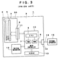
- the thermal printer 1 is assembled by detachably mounting a print unit 30 having a replaceable thermal print head 2, i.e., a driven unit, on a main unit 3.
- the thermal print head 2 of the thermal printer 1 has a plurality of linearly arranged heating elements 4, a driving IC (integrated circuit) 5 connected to the heating elements 4, and a connector 6 connected to the driving IC 5 and to an internal connector 11 for electrically connecting the print unit 30 to a main controller 10 included in the main unit 3 of the thermal printer 1.
- a driving IC integrated circuit
- the main controller 10 comprises a ROM (read-only memory) 7 initially and permanently storing pieces of information including control programs, a RAM (random-access memory) 8 temporarily storing printing data and such and allowing the retrieval of the stored data therefrom, and a CPU (central processing unit) 9 for processing data, connected to the ROM 7 and the RAM 8.
- the internal connector 11, a driving mechanism 12 including a feed motor and such, not shown, a display 13 for displaying pieces of information including the condition of the power source, failure in feeding a recording sheet and the like, and an external connector 14 through which to receive printing data from an external apparatus are connected to the main controller 10.
- the main controller 10, the driving mechanism 12 and the associated components of the thermal printer 1 form a printing system that drives the replaceable thermal print head 2 to print an image on a recording sheet, not shown.
- a communication cable 16 connected to an external apparatus 15, such as a personal computer, that provides printing data is detachably connected to the external connector 14 of the thermal printer 1.
- the thermal printer 1 receives printing data from the external apparatus 15 through the communication cable 16 and stores the same in the RAM 8 of the main controller 10.
- the CPU 9 drives the thermal print head 2 and the driving mechanism 12 according to the printing data stored in the RAM 8 and the control programs stored beforehand in the ROM 7 to print images with the thermal print head 2 on recording sheets successively fed by the driving mechanism 12.
- the print unit 30 is fabricated by mounting the thermal print head 2, the connector 6 and the driving IC 5 on a printed wiring board, not shown.
- the print unit 30 Since the thermal print head 2 of the thermal printer 1 is expendable, the print unit 30 must be replaced periodically with a new one. Usually, the number or the total length of recording sheets fed to the print unit 30 is counted by a mechanical counter, not shown, included in the driving mechanism 12 or by an electronic counter, not shown, comprised of the RAM 8 or the CPU 9 and included in the main controller 10, and a warning requesting the change of the print unit 30 is displayed on the display 13 when the count registered by the mechanical or electronic counter exceeds a predetermined limit value stored in the ROM 7 or a serviceman checks the count registered by the mechanical or electronic counter during maintenance work.
- This conventional thermal printer 1 has the following problems. If the print unit 30 is replaced with a new one before the warning is provided and the counter is not reset, or the counter is reset by mistake while the thermal print head 2 is in operation, a false count is registered by the counter.
- the thermal printer 1 needs statistical data about the life of the thermal print head 2 and other components for quality control purposes.
- a recording label not shown, for recording the count when replacing the print unit 30 is attached to the print unit 30 and the count is entered in the recording label when the print unit 30 is replaced.
- the serviceman collects periodically replaced print units 30 carrying the recording labels recording the counts.
- a second object of the present invention is to provide a printer capable of readily and surly collecting data useful for the quality control of the printer and the print unit and of storing the collected data in its print unit.
- a third object of the present invention is to provide a printer capable of providing accurate information about the life of its print unit.
- the present invention provides a print unit capable of being detachably mounted on the main unit of a printer, comprising a driven unit to be driven by the main unit, and an erasable programmable data storage unit for storing data representing the operating experiences of the print unit to enable the print unit to hold data useful for the quality control of the printer and the print unit. After removing the print unit from the main unit of the printer, data stored in the data storage unit can be read.
- the present invention provides also a printer detachably provided with a print unit comprising a driven unit and an erasable programmable data storage unit for storing data representing the operating experiences of the print unit, and capable of driving the driven unit of the print unit to print an image on a recording sheet.
- the printer detects the operating experiences of the print unit, stores data representing the detected operating experiences of the print unit in the data storage unit to enable the print unit to hold data useful for the quality control of the printer and the print unit.
- the data useful for the quality control of the print unit can be readily and surely stored in the data storage unit, and the data can be read from the data storage unit and processed after removing the print unit from the main unit.
- FIG. 1 A thermal printer in a preferred embodiment according to the present invention will be described hereinafter with reference to Figs. 1 and 2, in which parts like or corresponding to those previously described with reference to Fig. 1 are denoted by the same reference characters and the description thereof will be omitted.
- a thermal printer 17 has a print unit 30 detachably mounted on a main unit 19.
- the print unit 30 is formed by mounting a thermal print head 18, i.e., a driven unit, formed by linearly arranging a plurality of heating elements 4 and connecting a driving IC 5 to the heating elements 4, an EEPROM (electrically erasable programmable read-only memory) 20, i.e., a data storage unit, for storing data, and a connector 6 connected to the driving IC 5 and the EEPROM 20 on a printed wiring board, not shown.
- a thermal print head 18 i.e., a driven unit, formed by linearly arranging a plurality of heating elements 4 and connecting a driving IC 5 to the heating elements 4, an EEPROM (electrically erasable programmable read-only memory) 20, i.e., a data storage unit, for storing data, and a connector 6 connected to the driving IC 5 and the EEPROM 20 on a printed wiring board, not shown.
- EEPROM electrically erasable programmable read-only memory
- the main unit 19 comprises a main controller 24 comprising a ROM 21, a RAM 22 and a CPU 23 connected to the ROM 21 and the RAM 22, an internal connector 11, a driving mechanism 12, a display 13 and an external connector 14. the internal connector 11, the driving mechanism 12, the display 13 and the external connector 14 are connected to the main controller 24.
- the printer mechanism for driving the detachable thermal head 18 so as to perform image printing on a recording sheet comprises the main controller 24 and the driving mechanism 12.
- the thermal printer 17 includes a work measuring means for measuring the amount of work done by the print unit 30 including the thermal print head 18, and a data writing means for writing data representing the amount of work measured by the work measuring means in the EEPROM 20.
- the work measuring means and the data writing means are such constituted as to be controlled by the CPU 23 of the main controller 24. More concretely, the work measuring means counts pulses representing printing data applied to the thermal print head 18, and the progressively increasing number of the pulses counted by the work measuring means is stored in the EEPROM 20. The number of the pulses stored in the EEPROM 20 is incremented by one every time one pulse is counted.
- a limit value i.e., a maximum allowable count
- a comparator included in the CPU 23 of the main controller 24 compares the count stored in the EEPROM 20 of the print unit 30 and the limit value stored in the ROM 21.
- the CPU 23 executes a warning information output procedure to read warning information expressing that the count has exceeded the limit value from the ROM 21 and gives the warning information to the display 13 and an external apparatus 15, such as a personal computer.
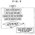
- the CPU 23 drives the thermal print head 18 and the driving mechanism 12 including a feed motor according to printing data received through the communication cable 16 from the external apparatus 15 and stored in the RAM 22, and a control program stored beforehand in the ROM 21. Then, the driving mechanism 12 feeds recording sheets successively and the thermal print head 18 prints images on the recording sheets.
- the pulses representing printing data are counted by a counter, not shown, consisting of the CPU 23, the ROM 21 and the RAM 22.
- the count stored in the EEPROM 20 is incremented by one every time one pulse representing printing data is counted by the counter to update the count stored in the EEPROM 20.
- the CPU 23 of the main unit 19 After updating the count stored in the EEPROM 20, the CPU 23 of the main unit 19 compares the limit value stored beforehand in the ROM 21 and the count stored in the EEPROM 20. If the count stored in the EEPROM 20 is smaller than the limit value stored in the ROM 21, the printing operation is continued.
- the CPU 23 Upon the detection of the increase of the count beyond the limit value while the thermal printer 17 is in printing operation, the CPU 23 reads the warning information requesting the replacement of the print unit 30 from the ROM 21, and gives the warning information to the display 13 to make the display 13 display the warning information, to the external apparatus 15 or to the thermal print head 18 to make the thermal print head 18 print the warning information on the recording sheet.
- the thermal printer 17 continues the printing operation even if the warning information is provided.
- the warning information prompts the operator of the thermal printer 17 to replace the print unit 30.
- the time when the expendable print unit 30 must be replaced with a new one can be accurately determined and it is possible to prompt the operator to replace the print unit 30 with a new one after the print unit 30 has done an appropriate amount of work.
- the operator need not perform troublesome work for resetting the counter, not shown. Since the thermal printer 17 need not be provided in its driving mechanism 12 with any counter for counting the number or the total length of recording sheets fed to the print unit 30, the thermal printer 17 can be formed in a compact, lightweight construction, and the productivity of the production line for manufacturing the thermal printer 17 can be enhanced.
- the statistical data of the life of the thermal print head 18 can be readily and surely obtained by reading the counts stored in the EEPROMs 20 of used print units 30 collected from the users.
- the present invention has been described as applied to the print unit 30 including the thermal print head 18 of the thermal printer 17, the present invention is not limited thereto in its practical application; the present invention is applicable also to other printers and other print units, such as end face light emission type electroluminescence printers (EL printers), end face light emission type electroluminescence print heads (EL heads), electrophotographic printers and organic photoconductive conductor drums (OPC drums) for electrophotography.
- EL printers end face light emission type electroluminescence printers
- EL heads end face light emission type electroluminescence print heads
- OPC drums organic photoconductive conductor drums
- the EEPROM 20 included in the print unit 30 in this embodiment as a data storage device may be substituted by a nonvolatile storage, such as a flash memory.
- the thermal printer 17 in this embodiment uses the number of pulses of printing data as the amount of work of the thermal print head 18, the work measuring means measures the amount of work and the data writing means writes the data representing the amount of work measured by the work measuring means in the EEPROM 20, the amount of work done by the thermal print head 18 may be represented by the number of electric driving pulses applied to the driving mechanism 12 by the main controller 10 or the total operating time of the thermal print head 18 measured by the main controller 10.
- the printer unit 30 in this embodiment stores only the number of pulses representing the printing data is stored as an amount of work done by the thermal print head 18 in the EEPROM 20, it is possible to store various kinds of information, other than the number of pulses representing the amount of work done by the thermal print head 18, useful for the quality control of the thermal print head 18 and the thermal printer 17, such as the date and time of operation of the thermal print head 18, the number of replaced print units and the frequency of jamming may be stored in the EEPROM 20.
- the EEPROM 20 for storing various kinds of information is incorporated into the thermal print head 18 and the data writing means incorporated into the main controller 24 included in the main unit 19 writes the amount of work done by the thermal print head 18 in the EEPROM 20 incorporated into the printer unit 30 to facilitate the collection of various kinds of information.
- the present invention is not limited in its practical application to the foregoing embodiment specifically described herein; the data writing means may be incorporated, for instance, into the thermal print head to enable the thermal print head to record the amount of work when the same is used on a conventional printer.
- the thermal printer in this embodiment continues its printing operation even after the CPU 23 has decided that the count stored in the EEPROM 20 has exceeded the limit value and the warning information has been provided, the printing operation of the thermal printer 17 may be interrupted when the warning information is provided.
Landscapes
- Accessory Devices And Overall Control Thereof (AREA)
Applications Claiming Priority (2)
| Application Number | Priority Date | Filing Date | Title |
|---|---|---|---|
| JP5125563A JPH06336070A (ja) | 1993-05-27 | 1993-05-27 | プリンタユニット及びプリンタ装置 |
| JP125563/93 | 1993-05-27 |
Publications (2)
| Publication Number | Publication Date |
|---|---|
| EP0626268A2 true EP0626268A2 (de) | 1994-11-30 |
| EP0626268A3 EP0626268A3 (de) | 1995-07-26 |
Family
ID=14913295
Family Applications (1)
| Application Number | Title | Priority Date | Filing Date |
|---|---|---|---|
| EP94303801A Withdrawn EP0626268A3 (de) | 1993-05-27 | 1994-05-26 | Drucker mit abnehmbarer Druckeinheit. |
Country Status (3)
| Country | Link |
|---|---|
| US (1) | US5786828A (de) |
| EP (1) | EP0626268A3 (de) |
| JP (1) | JPH06336070A (de) |
Cited By (5)
| Publication number | Priority date | Publication date | Assignee | Title |
|---|---|---|---|---|
| WO1998031548A1 (en) * | 1997-01-21 | 1998-07-23 | Hewlett-Packard Company | Ink container having electronic and mechanical features enabling plug compatibility between multiple supply sizes |
| EP0836947A3 (de) * | 1996-10-15 | 1999-09-01 | Hewlett-Packard Company | Verfahren und Vorrichtung zur Kodierung von Tropfengewicht |
| EP0873873A3 (de) * | 1997-04-25 | 1999-10-13 | Hewlett-Packard Company | Verbrauchsprodukt mit Speicher für eine Vorrichtung zur Bildaufzeichnung und Büroautomatisierung |
| EP0882595A3 (de) * | 1997-06-04 | 2000-03-29 | Hewlett-Packard Company | Tintenfüllstandsschätzung mittels Tropfenzählung und Tintenfüllstandsbestimmung |
| CN1088012C (zh) * | 1997-01-30 | 2002-07-24 | 惠普公司 | 其构形适合于小型供墨台用的油墨容器 |
Families Citing this family (22)
| Publication number | Priority date | Publication date | Assignee | Title |
|---|---|---|---|---|
| US6040670A (en) * | 1998-02-05 | 2000-03-21 | Canon Kabushiki Kaisha | Controller for printer carriage motor |
| CN101015996A (zh) * | 1998-11-02 | 2007-08-15 | 精工爱普生株式会社 | 一种墨盒与使用这种墨盒的打印机 |
| MY125897A (en) * | 1998-11-02 | 2006-08-30 | Seiko Epson Corp | Ink cartridge and printer using the same |
| JP2000218824A (ja) * | 1998-11-26 | 2000-08-08 | Seiko Epson Corp | インク容器およびそれを用いる印刷装置 |
| AU2003268576B2 (en) * | 1998-11-02 | 2006-10-19 | Seiko Epson Corporation | Ink Cartridge and Printer Using the Same |
| JP4314702B2 (ja) * | 1998-11-26 | 2009-08-19 | セイコーエプソン株式会社 | 印刷装置、書込方法およびプリンタ |
| JP2000218818A (ja) * | 1998-11-26 | 2000-08-08 | Seiko Epson Corp | インク容器およびそれを用いる印刷装置 |
| JP2001187457A (ja) * | 1998-11-26 | 2001-07-10 | Seiko Epson Corp | 印刷装置およびカートリッジ |
| JP4395943B2 (ja) | 1998-11-26 | 2010-01-13 | セイコーエプソン株式会社 | 印刷装置およびその情報の管理方法 |
| JP2000301738A (ja) * | 1998-11-26 | 2000-10-31 | Seiko Epson Corp | インク容器の適正判断方法およびインク容器の適正を判断する印刷装置 |
| DE19958946B4 (de) * | 1999-11-26 | 2006-11-09 | Francotyp-Postalia Gmbh | Verfahren zum Piraterieschutz eines Gerätes |
| JP4433578B2 (ja) * | 2000-06-29 | 2010-03-17 | ソニー株式会社 | 接続装置、接続方法及び接続機能を有するプログラムを記録したコンピュータ読み取り可能なプログラム格納媒体 |
| JP4023145B2 (ja) † | 2000-12-05 | 2007-12-19 | セイコーエプソン株式会社 | 印刷装置、インクカートリッジ |
| US6467888B2 (en) | 2001-02-21 | 2002-10-22 | Illinois Tool Works Inc. | Intelligent fluid delivery system for a fluid jet printing system |
| CA2379725C (en) * | 2001-04-03 | 2007-06-12 | Seiko Epson Corporation | Ink cartridge |
| KR100437377B1 (ko) * | 2002-02-15 | 2004-06-25 | 삼성전자주식회사 | 노즐의 이상유무를 체크할 수 있는 잉크젯프린터 및 그불량노즐 정보 제공방법 |
| US9296214B2 (en) | 2004-07-02 | 2016-03-29 | Zih Corp. | Thermal print head usage monitor and method for using the monitor |
| US8721203B2 (en) | 2005-10-06 | 2014-05-13 | Zih Corp. | Memory system and method for consumables of a printer |
| JP2009297997A (ja) * | 2008-06-12 | 2009-12-24 | Toshiba Tec Corp | 印刷装置及び印刷装置の制御方法 |
| EP2133209A3 (de) * | 2008-06-12 | 2010-02-24 | Toshiba TEC Kabushiki Kaisha | Druckvorrichtung |
| JP2010058357A (ja) * | 2008-09-03 | 2010-03-18 | Dainippon Printing Co Ltd | サーマルプリンタ |
| JP2010221599A (ja) * | 2009-03-24 | 2010-10-07 | Fujitsu Component Ltd | プリンタ |
Family Cites Families (11)
| Publication number | Priority date | Publication date | Assignee | Title |
|---|---|---|---|---|
| US4345262A (en) * | 1979-02-19 | 1982-08-17 | Canon Kabushiki Kaisha | Ink jet recording method |
| JPS6469376A (en) * | 1987-09-10 | 1989-03-15 | Nec Corp | Printing history data storing circuit |
| DE3880694D1 (de) * | 1988-07-25 | 1993-06-03 | Siemens Ag | Anordnung fuer druckeinrichtungen zur ueberwachung von druckmedium enthaltenden vorratsbehaeltern. |
| JPH02231148A (ja) * | 1988-11-04 | 1990-09-13 | Canon Inc | 記録ヘッド駆動方法および前記ヘッド駆動方法を用いた記録装置 |
| US5068806A (en) * | 1988-12-02 | 1991-11-26 | Spectra-Physics, Inc. | Method of determining useful life of cartridge for an ink jet printer |
| US5049898A (en) * | 1989-03-20 | 1991-09-17 | Hewlett-Packard Company | Printhead having memory element |
| US5276461A (en) * | 1989-04-18 | 1994-01-04 | Tokyo Electric Co., Ltd. | Electrophotographic printing device |
| EP0421806B1 (de) * | 1989-10-05 | 1999-03-17 | Canon Kabushiki Kaisha | Bilderzeugungsgerät |
| JPH04275156A (ja) * | 1991-03-01 | 1992-09-30 | Tokyo Electric Co Ltd | インクジェットプリンタ及びこのプリンタに使用されるインクカートリッジ |
| JPH07186430A (ja) * | 1991-11-04 | 1995-07-25 | Eastman Kodak Co | 感熱プリンタ |
| ATE194311T1 (de) * | 1992-02-10 | 2000-07-15 | Canon Kk | Tintenstrahlaufzeichnungsvorrichtung |
-
1993
- 1993-05-27 JP JP5125563A patent/JPH06336070A/ja active Pending
-
1994
- 1994-05-26 EP EP94303801A patent/EP0626268A3/de not_active Withdrawn
-
1996
- 1996-04-02 US US08/626,756 patent/US5786828A/en not_active Expired - Lifetime
Cited By (9)
| Publication number | Priority date | Publication date | Assignee | Title |
|---|---|---|---|---|
| US6305795B2 (en) | 1994-12-22 | 2001-10-23 | Winthrop D. Childers | Ink container having electronic and mechanical features enabling plug compatibility between multiple supply sizes |
| US5956057A (en) * | 1996-08-30 | 1999-09-21 | Hewlett-Packard Company | Ink container having electronic and mechanical features enabling plug compatibility between multiple supply sizes |
| EP0836947A3 (de) * | 1996-10-15 | 1999-09-01 | Hewlett-Packard Company | Verfahren und Vorrichtung zur Kodierung von Tropfengewicht |
| US6655775B1 (en) | 1996-10-15 | 2003-12-02 | Hewlett-Packard Development Company, L.P. | Method and apparatus for drop weight encoding |
| WO1998031548A1 (en) * | 1997-01-21 | 1998-07-23 | Hewlett-Packard Company | Ink container having electronic and mechanical features enabling plug compatibility between multiple supply sizes |
| CN1088012C (zh) * | 1997-01-30 | 2002-07-24 | 惠普公司 | 其构形适合于小型供墨台用的油墨容器 |
| EP0873873A3 (de) * | 1997-04-25 | 1999-10-13 | Hewlett-Packard Company | Verbrauchsprodukt mit Speicher für eine Vorrichtung zur Bildaufzeichnung und Büroautomatisierung |
| EP0882595A3 (de) * | 1997-06-04 | 2000-03-29 | Hewlett-Packard Company | Tintenfüllstandsschätzung mittels Tropfenzählung und Tintenfüllstandsbestimmung |
| US6151039A (en) * | 1997-06-04 | 2000-11-21 | Hewlett-Packard Company | Ink level estimation using drop count and ink level sense |
Also Published As
| Publication number | Publication date |
|---|---|
| EP0626268A3 (de) | 1995-07-26 |
| JPH06336070A (ja) | 1994-12-06 |
| US5786828A (en) | 1998-07-28 |
Similar Documents
| Publication | Publication Date | Title |
|---|---|---|
| US5786828A (en) | Detachable print unit having updatable condition memory and printer using the same | |
| EP1232868B1 (de) | Bilderzeugungsgerät mit Gebrauchsinformation | |
| EP0873873B1 (de) | Verbrauchsprodukt mit Speicher für eine Vorrichtung zur Bildaufzeichnung und Büroautomatisierung | |
| CN106527090B (zh) | 图像形成装置及消耗品管理方法 | |
| US5489971A (en) | Method and apparatus for detecting an exchange period for parts within an electrophotographic printing apparatus | |
| DE60017650T2 (de) | Verarbeitungssystem für austauschbare Module in einem digitalen Drucker | |
| EP1080930B1 (de) | Drucker, Steuerungsverfahren dafür und Datenspeichermedium | |
| DE69736415T2 (de) | Bilderzeugungsgerät und Steuerungsvorrichtung und -verfahren dafür | |
| US4855754A (en) | Control device for an image recorder | |
| US4974238A (en) | Counter arrangement for determining the life of consumables in office equipment | |
| EP0919392B1 (de) | Druckgerät, Verfahren zu seiner Steuerung und Speichermedium | |
| DE20321625U1 (de) | Patrone für Drucker und Druckvorrichtung | |
| US20180183974A1 (en) | Printer error checking with nfc technology | |
| US7430053B2 (en) | Tracking component usage in a printing device | |
| JP2002370378A (ja) | 印刷記録材容器の検出 | |
| CN111516397A (zh) | 一种标签纸识别方法、装置、设备及可读存储介质 | |
| US6798434B2 (en) | Printing device | |
| US6370340B1 (en) | Method and apparatus for monitoring parameters corresponding to operation of an electrophotographic marking machine | |
| JP2003191583A (ja) | 印字装置 | |
| US20070063013A1 (en) | Systems and methods for maintaining warranty claim information | |
| JP5619564B2 (ja) | 検証装置 | |
| JP4307770B2 (ja) | ラベルプリンタ | |
| JP2008152541A (ja) | 印刷装置及びログデータ管理方法 | |
| JPH0667483A (ja) | ドラム周辺ユニットの通信エラー防止装置 | |
| JP2006065187A (ja) | 写真処理装置における消耗品管理システム |
Legal Events
| Date | Code | Title | Description |
|---|---|---|---|
| PUAI | Public reference made under article 153(3) epc to a published international application that has entered the european phase |
Free format text: ORIGINAL CODE: 0009012 |
|
| 17P | Request for examination filed |
Effective date: 19940603 |
|
| AK | Designated contracting states |
Kind code of ref document: A2 Designated state(s): BE DE ES FR GB |
|
| PUAL | Search report despatched |
Free format text: ORIGINAL CODE: 0009013 |
|
| AK | Designated contracting states |
Kind code of ref document: A3 Designated state(s): BE DE ES FR GB |
|
| RAP1 | Party data changed (applicant data changed or rights of an application transferred) |
Owner name: KABUSHIKI KAISHA TEC |
|
| 17Q | First examination report despatched |
Effective date: 19960701 |
|
| STAA | Information on the status of an ep patent application or granted ep patent |
Free format text: STATUS: THE APPLICATION IS DEEMED TO BE WITHDRAWN |
|
| 18D | Application deemed to be withdrawn |
Effective date: 19961112 |