EP0626276A1 - Stylo-pointe-bille - Google Patents
Stylo-pointe-bille Download PDFInfo
- Publication number
- EP0626276A1 EP0626276A1 EP94104220A EP94104220A EP0626276A1 EP 0626276 A1 EP0626276 A1 EP 0626276A1 EP 94104220 A EP94104220 A EP 94104220A EP 94104220 A EP94104220 A EP 94104220A EP 0626276 A1 EP0626276 A1 EP 0626276A1
- Authority
- EP
- European Patent Office
- Prior art keywords
- ball
- tip
- ink
- valve chamber
- point pen
- Prior art date
- Legal status (The legal status is an assumption and is not a legal conclusion. Google has not performed a legal analysis and makes no representation as to the accuracy of the status listed.)
- Granted
Links
- 230000003247 decreasing effect Effects 0.000 claims abstract description 8
- 229920005989 resin Polymers 0.000 claims description 17
- 239000011347 resin Substances 0.000 claims description 17
- 230000008016 vaporization Effects 0.000 claims description 12
- 230000009974 thixotropic effect Effects 0.000 claims description 11
- 238000007789 sealing Methods 0.000 claims description 10
- 230000002093 peripheral effect Effects 0.000 claims description 8
- 238000005096 rolling process Methods 0.000 claims description 8
- 230000003068 static effect Effects 0.000 claims description 8
- 239000006261 foam material Substances 0.000 claims description 5
- 239000000463 material Substances 0.000 claims description 4
- 238000003825 pressing Methods 0.000 claims description 3
- 238000009834 vaporization Methods 0.000 description 6
- 230000000694 effects Effects 0.000 description 5
- 230000007547 defect Effects 0.000 description 4
- 238000000465 moulding Methods 0.000 description 4
- 239000004033 plastic Substances 0.000 description 4
- XLYOFNOQVPJJNP-UHFFFAOYSA-N water Substances O XLYOFNOQVPJJNP-UHFFFAOYSA-N 0.000 description 4
- 239000004743 Polypropylene Substances 0.000 description 3
- 239000000835 fiber Substances 0.000 description 3
- 238000004519 manufacturing process Methods 0.000 description 3
- 238000000926 separation method Methods 0.000 description 3
- 229920003002 synthetic resin Polymers 0.000 description 3
- 239000000057 synthetic resin Substances 0.000 description 3
- BQCADISMDOOEFD-UHFFFAOYSA-N Silver Chemical compound [Ag] BQCADISMDOOEFD-UHFFFAOYSA-N 0.000 description 2
- 230000007423 decrease Effects 0.000 description 2
- 238000001035 drying Methods 0.000 description 2
- 238000000034 method Methods 0.000 description 2
- 230000001105 regulatory effect Effects 0.000 description 2
- 229910052709 silver Inorganic materials 0.000 description 2
- 239000004332 silver Substances 0.000 description 2
- 230000002411 adverse Effects 0.000 description 1
- 230000015572 biosynthetic process Effects 0.000 description 1
- 238000004891 communication Methods 0.000 description 1
- 230000006866 deterioration Effects 0.000 description 1
- 230000002542 deteriorative effect Effects 0.000 description 1
- 238000001746 injection moulding Methods 0.000 description 1
- -1 polypropylene Polymers 0.000 description 1
- 229920001155 polypropylene Polymers 0.000 description 1
- 230000002265 prevention Effects 0.000 description 1
- 230000035939 shock Effects 0.000 description 1
- 239000002689 soil Substances 0.000 description 1
- 238000009423 ventilation Methods 0.000 description 1
Images




Classifications
-
- B—PERFORMING OPERATIONS; TRANSPORTING
- B43—WRITING OR DRAWING IMPLEMENTS; BUREAU ACCESSORIES
- B43K—IMPLEMENTS FOR WRITING OR DRAWING
- B43K7/00—Ball-point pens
- B43K7/01—Ball-point pens for low viscosity liquid ink
-
- B—PERFORMING OPERATIONS; TRANSPORTING
- B43—WRITING OR DRAWING IMPLEMENTS; BUREAU ACCESSORIES
- B43K—IMPLEMENTS FOR WRITING OR DRAWING
- B43K23/00—Holders or connectors for writing implements; Means for protecting the writing-points
- B43K23/08—Protecting means, e.g. caps
- B43K23/12—Protecting means, e.g. caps for pens
- B43K23/122—Protecting means, e.g. caps for pens with means for preventing choking
- B43K23/124—Protecting means, e.g. caps for pens with means for preventing choking comprising an air passage
-
- B—PERFORMING OPERATIONS; TRANSPORTING
- B43—WRITING OR DRAWING IMPLEMENTS; BUREAU ACCESSORIES
- B43K—IMPLEMENTS FOR WRITING OR DRAWING
- B43K7/00—Ball-point pens
- B43K7/02—Ink reservoirs; Ink cartridges
- B43K7/08—Preventing leakage
Definitions
- this method suffers from another drawback which arises when centrifugal treatment is effected at manufacturing stage in order to remove bubbles mingled in the ink filled. More specifically, when the centrifugal operation is performed, the ball is pushed toward the projected bar area by the centrifugal force so that the ball is bitten and fixed by the projected bars.
- the water type ball-point pen takes a higher cost for materials used since the water type ball-point pen uses silver fibers for keeping the ink. Additionally, the water type ball-point pen has a drawback that consumption of ink cannot be known.
- Typical ball-point pens are suffering from bad write-feeling with writing since there is a gap between the tip opening of the mouthpiece and the tip and therefore the tip rattles or sways.
- ventilating means is provided between the pen tip and the cap to prevent the above effect, but this gives rise to adverse influence with regard to vaporization of the ink.
- a fourth object of the present invention is to provide a ball-point pen with a refill which, upon manufacture of refills of ball-point pens wherein the refills having been filled up with ink and an ink follower are bundled and undergo the centrifugal operation so as to remove air bubbles mingled in the ink, allows the ink to be defoamed in such an assured manner that the bundle of all the refills may be abutted at their tip ends against an abutting surface inside a container of a centrifugal separator.
- a fifth object of the present invention is to provide a ball-point pen capable of clearly informing the exhausted state of ink without deteriorating writing performances.
- a sixth object of the present invention is to provide a ball-point pen which can regulate elevation of the pressure inside the pen when a cap is attached so as not to prevent air from flowing into the ink and which can prevent the vaporization of ink by simple means.
- a seventh object of the present invention is to provide a ball-point pen which allows air to pass through a pen cap so that it could prevent hazards such as choking in case an infant accidentally swallowed the cap and the cap stuck into its throat.
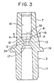
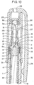
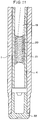
- a ball-point pen of the present invention includes a joint which defines a ball valve seat 13 at an approximately central portion thereof in axial direction.
- the ball valve seat 13 constitutes one end of a conduit 17 which communicates with an ink reservoir.
- the joint also defines a valve chamber 12 in which a ball valve 14 is put with play and a tip fitting hole 10 in the front part of the valve chamber.
- the joint further includes means regulating the ball valve 14 not to stop up the end hole of a tip 5 which is fit in the tip fitting hole 10 when the tip fitting hole 10 is positioned down.
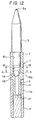
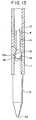
- Figs.12 to 15 Still another alternate is shown in Figs.12 to 15.
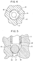
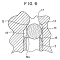
- the axis of the conduit is made coincident with that of the tip end hole while preferably a plurality of vertical ribs 15a each having a different height are disposed in required positions on the peripheral wall of the valve chamber.
- These ribs are provided in such a manner that a cylindrical space may be created by top surfaces of these ribs and the axis of the thus formed cylindrical space is made eccentric to the axis of the tip end hole.
- a valve which has a spherical shape at least on a surface that contacts with the conduit is put with play in the thus formed cylindrical space.
- the axis of the ball valve placed on the communicating opening to the conduit is made eccentric to the axis of the conduit.
- the ball valve may be structured by a hemispheric form with a projection 14a on the plane side.
- the projection 14a must be formed enough long to keep the hemispheric portion of the valve to orient toward the conduit and must be shaped so as not to be fit into the tip end hole.
- This hemispheric structure makes it possible to limit the length of the vertical ribs in the valve chamber to the vicinity of the ball valve seat.
- the joint is mainly composed of a squeezing pipe portion 7, a flange 16 and a fitting pipe portion 11.
- a plurality of vertical ribs 8 of tapered form are extended along the length of the squeezing pipe portion 7 to the flange 16. These vertical ribs 8 press an inner step portion of a mouthpiece 2 (called as plastic mouthpiece if it is made of plastic) to contact with a good bite therewith when the mouthpiece 2 is screwed into the barrel so that the tip will not sway at writing.
- the aforementioned ribs 8 are formed with linearly or curvingly slanting surfaces and provided at required positions on the outside surface of the squeezing pipe portion 7 while rear ends of the rib are connected with the flange 16 in level with the outside diameter surface of the flange.
- the aforementioned mouthpiece 2 is fixed to the barrel 1 with the inner step portion of the mouthpiece being contacted with a good bite to the peripheral portions of the ribs. Further, there is provided a ventilating passage communicating from the tip to an inner space 1a inside the barrel.
- Fig.1 is a vertical cross-section showing a whole part of a ball-point pen with a tip oriented upward.
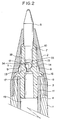
- Fig.2 is a vertical section showing a joint portion as a main part of Fig.1.
- the squeezing pipe portion 7 on the front side is provided on its outside surface with a plurality of tapered vertical ribs 8.
- the fitting pipe portion 11 is secured to an ink reservoir 4, which in turn is fit in with or covered by a barrel 1.
- a tip 5 having a ball at the top thereof is press-fitted into, a tip fitting hole 10 disposed at the front end of the squeezing pipe portion 7.
- the joint 3 is integrally molded of an elastically deformable synthetic resin and defines a valve chamber 12 behind the tip fitting hole 10 communicating therewith.
- valve chamber 12 The principal surface of the valve chamber 12 is defined eccentrically to the axis of the tip fitting hole 10 with the valve chamber 12 being contained within a range of the inner periphery of the tip fitting hole 10. Further, the valve chamber 12 includes a ball valve seat 13 at the rear part thereof while the axis of the hole of the ball valve seat 13 is made eccentric with a proper eccentricity (eccentricity S) relative to the axis of the tip fitting hole 10. Moreover, a channel 15 is provided on one side of the valve chamber space.
- the joint 3 securely joins the tip 5 with the ink reservoir 4 full of ink to form a writing portion.
- the thus formed writing portion is inserted into the barrel 1 from the front end thereof until the rear side of the flange 16 of the joint 3 abuts the front side of the barrel end 6.
- the mouthpiece 2 is screwed into the barrel end 6 of the barrel 1 with vertical ribs 8 of the squeezing pipe portion 7 being in a biting contact with the inner step portion 9 of the mouthpiece 2.
- a vent or some vents for communicating with the inner space of the barrel are provided in appropriate positions on the barrel 1.
- a vent (not shown) in communication with the barrel inside is provided in a plug 22 squeezed at the rear end of the barrel 1.
- the flange 16 is provided on the rear side of the squeezing pipe portion 7 and the fitting pipe portion 11 is extended backward from the rear side of the flange 16.
- a colored resin piece having a specific weight approximately equal to that of the follower is immersed in the follower 20.
- the colored resin piece is of a pipe piece 21 composed of PP resin or the like, and is immersed in the follower 20 with the inside and outside of the piece 21 filled with the follower 20.
- the pipe piece 21 is positioned such that a rear part of the pipe piece 21 projects over the rear end of the follower 20.
- the colored resin piece is not limited to the pipe piece but may be replaced with a rod piece or ball which has an outside diameter properly smaller than the inner diameter of the ink reservoir 4 and is immersed in the follower.
- the barrel 1 is formed of a transparent resin molding so that the consumption of ink can be seen.
- a ventilating passage from the clearance at the front opening of the mouthpiece between the tip 5 penetrated therethrough and the opening edge is formed so as to be introduced through channels between ribs 8 disposed on the squeezing pipe portion 7 and the inner surface of the mouthpiece 2 and recesses 6a formed at the front side of the barrel end 6 to the inner space 1a inside the barrel 1.
- a vent or some vents are provided, as required, on a side surface of the barrel 1, or on the plug 22 or between the plug and the barrel, in order to communicate between the inner space 1a and the outside atmosphere.
Landscapes
- Pens And Brushes (AREA)
Applications Claiming Priority (4)
| Application Number | Priority Date | Filing Date | Title |
|---|---|---|---|
| JP1993012171U JP2604349Y2 (ja) | 1993-03-18 | 1993-03-18 | ボールペン |
| JP12171/93U | 1993-03-18 | ||
| JP31856/93U | 1993-05-24 | ||
| JP3185693U JPH0683380U (ja) | 1993-05-24 | 1993-05-24 | ボールペン |
Publications (2)
| Publication Number | Publication Date |
|---|---|
| EP0626276A1 true EP0626276A1 (fr) | 1994-11-30 |
| EP0626276B1 EP0626276B1 (fr) | 1998-10-07 |
Family
ID=26347745
Family Applications (1)
| Application Number | Title | Priority Date | Filing Date |
|---|---|---|---|
| EP19940104220 Expired - Lifetime EP0626276B1 (fr) | 1993-03-18 | 1994-03-17 | Stylo-pointe-bille |
Country Status (2)
| Country | Link |
|---|---|
| EP (1) | EP0626276B1 (fr) |
| DE (1) | DE69413744T2 (fr) |
Cited By (10)
| Publication number | Priority date | Publication date | Assignee | Title |
|---|---|---|---|---|
| EP0685348A4 (fr) * | 1993-12-06 | 1996-04-24 | Mitsubishi Pencil Co | Stylo a bille. |
| FR2730944A1 (fr) * | 1995-02-28 | 1996-08-30 | Mitsubishi Pencil Co | Stylo a bille |
| GB2281257B (en) * | 1993-08-31 | 1997-04-09 | Mitsubishi Pencil Co | Ink follower for aqueous ballpoint pen |
| EP0911181A1 (fr) * | 1997-10-15 | 1999-04-28 | The Pilot Ink Co., Ltd. | Instrument d'écriture |
| FR2785570A1 (fr) * | 1999-10-08 | 2000-05-12 | Bima 83 | Piston suiveur d'encre pour stylo a bille |
| FR2785569A1 (fr) * | 1998-11-09 | 2000-05-12 | Bima 83 | Piston suiveur d'encre pour stylo a bille et son procede de fabrication |
| EP0972654A4 (fr) * | 1997-12-03 | 2003-11-26 | Sakura Color Prod Corp | Applicateur d'encre, mecanisme de prevention du retour d'encre de cet applicateur d'encre et pointe de plume |
| EP1462495A1 (fr) * | 2003-03-26 | 2004-09-29 | Kabushiki Kaisha Pilot Corporation | Encre aqueuse pour stylo à bille et stylo à bille utilisant cette encre |
| US6837640B2 (en) | 1999-09-14 | 2005-01-04 | Sakura Color Products Corp. | Applicator |
| EP1658999A4 (fr) * | 2003-08-25 | 2009-08-26 | Mitsubishi Pencil Co | Instrument d'ecriture |
Citations (6)
| Publication number | Priority date | Publication date | Assignee | Title |
|---|---|---|---|---|
| FR971021A (fr) * | 1947-04-02 | 1951-01-11 | Biro Patente A G | Perfectionnements aux instruments pour écrire à réservoir |
| FR1056717A (fr) * | 1952-05-21 | 1954-03-02 | Organe combiné d'écriture à bille à écriture variable | |
| FR1497176A (fr) * | 1966-10-20 | 1967-10-06 | Paper Mate Mfg Co | Dispositif obturateur destiné à suivre le niveau d'encre d'une cartouche |
| GB2078175A (en) * | 1980-06-10 | 1982-01-06 | Zebra Co Ltd | A ball-point pen |
| WO1986004345A1 (fr) * | 1985-01-23 | 1986-07-31 | The Gillette Company | Instrument d'ecriture a bille contenant une composition aqueuse d'encre |
| JPH052067Y2 (fr) * | 1987-06-03 | 1993-01-19 |
-
1994
- 1994-03-17 DE DE1994613744 patent/DE69413744T2/de not_active Expired - Fee Related
- 1994-03-17 EP EP19940104220 patent/EP0626276B1/fr not_active Expired - Lifetime
Patent Citations (6)
| Publication number | Priority date | Publication date | Assignee | Title |
|---|---|---|---|---|
| FR971021A (fr) * | 1947-04-02 | 1951-01-11 | Biro Patente A G | Perfectionnements aux instruments pour écrire à réservoir |
| FR1056717A (fr) * | 1952-05-21 | 1954-03-02 | Organe combiné d'écriture à bille à écriture variable | |
| FR1497176A (fr) * | 1966-10-20 | 1967-10-06 | Paper Mate Mfg Co | Dispositif obturateur destiné à suivre le niveau d'encre d'une cartouche |
| GB2078175A (en) * | 1980-06-10 | 1982-01-06 | Zebra Co Ltd | A ball-point pen |
| WO1986004345A1 (fr) * | 1985-01-23 | 1986-07-31 | The Gillette Company | Instrument d'ecriture a bille contenant une composition aqueuse d'encre |
| JPH052067Y2 (fr) * | 1987-06-03 | 1993-01-19 |
Non-Patent Citations (1)
| Title |
|---|
| WOODYARD D.: "ink fit for spacemen", ENGINEERING, vol. 209, no. 5428, 15 May 1970 (1970-05-15), pages 507 * |
Cited By (15)
| Publication number | Priority date | Publication date | Assignee | Title |
|---|---|---|---|---|
| GB2281257B (en) * | 1993-08-31 | 1997-04-09 | Mitsubishi Pencil Co | Ink follower for aqueous ballpoint pen |
| EP0685348A4 (fr) * | 1993-12-06 | 1996-04-24 | Mitsubishi Pencil Co | Stylo a bille. |
| US5711626A (en) * | 1993-12-06 | 1998-01-27 | Mitsubishi Pencil Kabushiki Kaisha | Ball-point pen with back flow stop |
| FR2730944A1 (fr) * | 1995-02-28 | 1996-08-30 | Mitsubishi Pencil Co | Stylo a bille |
| EP0911181A1 (fr) * | 1997-10-15 | 1999-04-28 | The Pilot Ink Co., Ltd. | Instrument d'écriture |
| US6010269A (en) * | 1997-10-15 | 2000-01-04 | The Pilot Ink Co., Ltd. | Writing implement |
| EP0972654A4 (fr) * | 1997-12-03 | 2003-11-26 | Sakura Color Prod Corp | Applicateur d'encre, mecanisme de prevention du retour d'encre de cet applicateur d'encre et pointe de plume |
| FR2785569A1 (fr) * | 1998-11-09 | 2000-05-12 | Bima 83 | Piston suiveur d'encre pour stylo a bille et son procede de fabrication |
| WO2000027651A1 (fr) * | 1998-11-09 | 2000-05-18 | Societe Bic | Piston suiveur d'encre pour stylo a bille et son procede de fabrication |
| EP1209004A3 (fr) * | 1998-11-09 | 2005-08-31 | Société BIC | Piston suiveur d'encre pour stylo à bille et son proédé de fabrication |
| KR100764317B1 (ko) * | 1998-11-09 | 2007-10-05 | 소시에떼 빅 | 볼펜용 잉크 추적 피스톤과 그 제조방법 |
| US6837640B2 (en) | 1999-09-14 | 2005-01-04 | Sakura Color Products Corp. | Applicator |
| FR2785570A1 (fr) * | 1999-10-08 | 2000-05-12 | Bima 83 | Piston suiveur d'encre pour stylo a bille |
| EP1462495A1 (fr) * | 2003-03-26 | 2004-09-29 | Kabushiki Kaisha Pilot Corporation | Encre aqueuse pour stylo à bille et stylo à bille utilisant cette encre |
| EP1658999A4 (fr) * | 2003-08-25 | 2009-08-26 | Mitsubishi Pencil Co | Instrument d'ecriture |
Also Published As
| Publication number | Publication date |
|---|---|
| DE69413744T2 (de) | 1999-06-02 |
| EP0626276B1 (fr) | 1998-10-07 |
| DE69413744D1 (de) | 1998-11-12 |
Similar Documents
| Publication | Publication Date | Title |
|---|---|---|
| EP0626276B1 (fr) | Stylo-pointe-bille | |
| CA2153589C (fr) | Stylo a bille | |
| US5709493A (en) | Ballpoint pen having a backflow preventing mechanism | |
| US4928121A (en) | Universal plotter pen having improved marking fluid flow characteristics | |
| JP2604349Y2 (ja) | ボールペン | |
| JP2681763B2 (ja) | 筆記具 | |
| JP3724885B2 (ja) | ボールペン | |
| JPH07237387A (ja) | ボールペン | |
| JP2004098462A (ja) | 直液式筆記具 | |
| US6435752B1 (en) | Correction pen with pressure adjusting structure | |
| JPH0663376U (ja) | ボールペン | |
| CN220242855U (zh) | 一种通气的笔芯帽 | |
| JP2590453Y2 (ja) | ボールペン | |
| JP2003231387A (ja) | ボールペン | |
| JP2590455Y2 (ja) | ボールペン | |
| JP2606975Y2 (ja) | ボールペン | |
| JP5340010B2 (ja) | 筆記具及びその製造方法 | |
| JPH0683377U (ja) | ボールペン | |
| JPH09378U (ja) | ボールペン | |
| JPH07299988A (ja) | ボールペン | |
| JPH09104193A (ja) | 直液式筆記具 | |
| JP3179589B2 (ja) | 筆記具 | |
| JP2606980Y2 (ja) | ボールペン | |
| JPH0667078U (ja) | ボールペン | |
| JPH0725257Y2 (ja) | 流体吐出具 |
Legal Events
| Date | Code | Title | Description |
|---|---|---|---|
| PUAI | Public reference made under article 153(3) epc to a published international application that has entered the european phase |
Free format text: ORIGINAL CODE: 0009012 |
|
| AK | Designated contracting states |
Kind code of ref document: A1 Designated state(s): DE FR GB IT |
|
| 17P | Request for examination filed |
Effective date: 19950314 |
|
| 17Q | First examination report despatched |
Effective date: 19960209 |
|
| GRAG | Despatch of communication of intention to grant |
Free format text: ORIGINAL CODE: EPIDOS AGRA |
|
| GRAG | Despatch of communication of intention to grant |
Free format text: ORIGINAL CODE: EPIDOS AGRA |
|
| GRAG | Despatch of communication of intention to grant |
Free format text: ORIGINAL CODE: EPIDOS AGRA |
|
| GRAH | Despatch of communication of intention to grant a patent |
Free format text: ORIGINAL CODE: EPIDOS IGRA |
|
| GRAH | Despatch of communication of intention to grant a patent |
Free format text: ORIGINAL CODE: EPIDOS IGRA |
|
| GRAA | (expected) grant |
Free format text: ORIGINAL CODE: 0009210 |
|
| AK | Designated contracting states |
Kind code of ref document: B1 Designated state(s): DE FR GB IT |
|
| REF | Corresponds to: |
Ref document number: 69413744 Country of ref document: DE Date of ref document: 19981112 |
|
| ET | Fr: translation filed | ||
| PLBE | No opposition filed within time limit |
Free format text: ORIGINAL CODE: 0009261 |
|
| STAA | Information on the status of an ep patent application or granted ep patent |
Free format text: STATUS: NO OPPOSITION FILED WITHIN TIME LIMIT |
|
| 26N | No opposition filed | ||
| REG | Reference to a national code |
Ref country code: GB Ref legal event code: IF02 |
|
| PGFP | Annual fee paid to national office [announced via postgrant information from national office to epo] |
Ref country code: GB Payment date: 20040225 Year of fee payment: 11 |
|
| PGFP | Annual fee paid to national office [announced via postgrant information from national office to epo] |
Ref country code: FR Payment date: 20040318 Year of fee payment: 11 |
|
| PGFP | Annual fee paid to national office [announced via postgrant information from national office to epo] |
Ref country code: DE Payment date: 20040331 Year of fee payment: 11 |
|
| PG25 | Lapsed in a contracting state [announced via postgrant information from national office to epo] |
Ref country code: IT Free format text: LAPSE BECAUSE OF NON-PAYMENT OF DUE FEES;WARNING: LAPSES OF ITALIAN PATENTS WITH EFFECTIVE DATE BEFORE 2007 MAY HAVE OCCURRED AT ANY TIME BEFORE 2007. THE CORRECT EFFECTIVE DATE MAY BE DIFFERENT FROM THE ONE RECORDED. Effective date: 20050317 Ref country code: GB Free format text: LAPSE BECAUSE OF NON-PAYMENT OF DUE FEES Effective date: 20050317 |
|
| PG25 | Lapsed in a contracting state [announced via postgrant information from national office to epo] |
Ref country code: DE Free format text: LAPSE BECAUSE OF NON-PAYMENT OF DUE FEES Effective date: 20051001 |
|
| GBPC | Gb: european patent ceased through non-payment of renewal fee |
Effective date: 20050317 |
|
| PG25 | Lapsed in a contracting state [announced via postgrant information from national office to epo] |
Ref country code: FR Free format text: LAPSE BECAUSE OF NON-PAYMENT OF DUE FEES Effective date: 20051130 |
|
| REG | Reference to a national code |
Ref country code: FR Ref legal event code: ST Effective date: 20051130 |