EP0627298A2 - Procédé et dispositif pour former une bride de maintien autour d'une fermeture de récipient - Google Patents
Procédé et dispositif pour former une bride de maintien autour d'une fermeture de récipient Download PDFInfo
- Publication number
- EP0627298A2 EP0627298A2 EP94303923A EP94303923A EP0627298A2 EP 0627298 A2 EP0627298 A2 EP 0627298A2 EP 94303923 A EP94303923 A EP 94303923A EP 94303923 A EP94303923 A EP 94303923A EP 0627298 A2 EP0627298 A2 EP 0627298A2
- Authority
- EP
- European Patent Office
- Prior art keywords
- insert article
- article
- parison
- bead
- insert
- Prior art date
- Legal status (The legal status is an assumption and is not a legal conclusion. Google has not performed a legal analysis and makes no representation as to the accuracy of the status listed.)
- Granted
Links
- 238000000034 method Methods 0.000 title claims abstract description 34
- 239000011324 bead Substances 0.000 claims abstract description 40
- 239000012815 thermoplastic material Substances 0.000 claims abstract description 24
- 238000000465 moulding Methods 0.000 claims abstract description 9
- 238000003825 pressing Methods 0.000 claims description 15
- 238000011049 filling Methods 0.000 claims description 10
- 229920001169 thermoplastic Polymers 0.000 claims description 8
- 239000004416 thermosoftening plastic Substances 0.000 claims description 8
- 238000007789 sealing Methods 0.000 abstract description 10
- 238000004519 manufacturing process Methods 0.000 description 14
- 229920001971 elastomer Polymers 0.000 description 10
- 230000014759 maintenance of location Effects 0.000 description 8
- 230000002093 peripheral effect Effects 0.000 description 8
- 238000003780 insertion Methods 0.000 description 6
- 230000037431 insertion Effects 0.000 description 6
- 239000000463 material Substances 0.000 description 6
- 239000002131 composite material Substances 0.000 description 4
- 239000007788 liquid Substances 0.000 description 4
- 238000000071 blow moulding Methods 0.000 description 3
- 238000007664 blowing Methods 0.000 description 3
- 238000001816 cooling Methods 0.000 description 3
- 239000003814 drug Substances 0.000 description 3
- 230000007246 mechanism Effects 0.000 description 3
- 230000036961 partial effect Effects 0.000 description 3
- 230000002829 reductive effect Effects 0.000 description 3
- 238000001990 intravenous administration Methods 0.000 description 2
- 230000000717 retained effect Effects 0.000 description 2
- 238000007666 vacuum forming Methods 0.000 description 2
- 239000004743 Polypropylene Substances 0.000 description 1
- 230000002411 adverse Effects 0.000 description 1
- 238000000429 assembly Methods 0.000 description 1
- 230000000712 assembly Effects 0.000 description 1
- 230000009286 beneficial effect Effects 0.000 description 1
- 230000015572 biosynthetic process Effects 0.000 description 1
- 230000006835 compression Effects 0.000 description 1
- 238000007906 compression Methods 0.000 description 1
- 229940079593 drug Drugs 0.000 description 1
- 230000000694 effects Effects 0.000 description 1
- 239000011888 foil Substances 0.000 description 1
- 230000005484 gravity Effects 0.000 description 1
- 238000010438 heat treatment Methods 0.000 description 1
- 229920001903 high density polyethylene Polymers 0.000 description 1
- 239000004700 high-density polyethylene Substances 0.000 description 1
- 238000009434 installation Methods 0.000 description 1
- 229920001684 low density polyethylene Polymers 0.000 description 1
- 239000004702 low-density polyethylene Substances 0.000 description 1
- 238000012986 modification Methods 0.000 description 1
- 230000004048 modification Effects 0.000 description 1
- -1 polypropylene Polymers 0.000 description 1
- 229920001155 polypropylene Polymers 0.000 description 1
- 238000002360 preparation method Methods 0.000 description 1
- 230000001681 protective effect Effects 0.000 description 1
- 229920002725 thermoplastic elastomer Polymers 0.000 description 1
Images


Classifications
-
- B—PERFORMING OPERATIONS; TRANSPORTING
- B29—WORKING OF PLASTICS; WORKING OF SUBSTANCES IN A PLASTIC STATE IN GENERAL
- B29C—SHAPING OR JOINING OF PLASTICS; SHAPING OF MATERIAL IN A PLASTIC STATE, NOT OTHERWISE PROVIDED FOR; AFTER-TREATMENT OF THE SHAPED PRODUCTS, e.g. REPAIRING
- B29C49/00—Blow-moulding, i.e. blowing a preform or parison to a desired shape within a mould; Apparatus therefor
- B29C49/20—Blow-moulding, i.e. blowing a preform or parison to a desired shape within a mould; Apparatus therefor of articles having inserts or reinforcements ; Handling of inserts or reinforcements
-
- B—PERFORMING OPERATIONS; TRANSPORTING
- B29—WORKING OF PLASTICS; WORKING OF SUBSTANCES IN A PLASTIC STATE IN GENERAL
- B29C—SHAPING OR JOINING OF PLASTICS; SHAPING OF MATERIAL IN A PLASTIC STATE, NOT OTHERWISE PROVIDED FOR; AFTER-TREATMENT OF THE SHAPED PRODUCTS, e.g. REPAIRING
- B29C49/00—Blow-moulding, i.e. blowing a preform or parison to a desired shape within a mould; Apparatus therefor
- B29C49/02—Combined blow-moulding and manufacture of the preform or the parison
- B29C49/04—Extrusion blow-moulding
-
- B—PERFORMING OPERATIONS; TRANSPORTING
- B29—WORKING OF PLASTICS; WORKING OF SUBSTANCES IN A PLASTIC STATE IN GENERAL
- B29C—SHAPING OR JOINING OF PLASTICS; SHAPING OF MATERIAL IN A PLASTIC STATE, NOT OTHERWISE PROVIDED FOR; AFTER-TREATMENT OF THE SHAPED PRODUCTS, e.g. REPAIRING
- B29C49/00—Blow-moulding, i.e. blowing a preform or parison to a desired shape within a mould; Apparatus therefor
- B29C49/42—Component parts, details or accessories; Auxiliary operations
- B29C49/48—Moulds
- B29C49/4802—Moulds with means for locally compressing part(s) of the parison in the main blowing cavity
- B29C49/4817—Moulds with means for locally compressing part(s) of the parison in the main blowing cavity with means for closing off parison ends
-
- B—PERFORMING OPERATIONS; TRANSPORTING
- B29—WORKING OF PLASTICS; WORKING OF SUBSTANCES IN A PLASTIC STATE IN GENERAL
- B29C—SHAPING OR JOINING OF PLASTICS; SHAPING OF MATERIAL IN A PLASTIC STATE, NOT OTHERWISE PROVIDED FOR; AFTER-TREATMENT OF THE SHAPED PRODUCTS, e.g. REPAIRING
- B29C65/00—Joining or sealing of preformed parts, e.g. welding of plastics materials; Apparatus therefor
- B29C65/56—Joining or sealing of preformed parts, e.g. welding of plastics materials; Apparatus therefor using mechanical means or mechanical connections, e.g. form-fits
- B29C65/567—Joining or sealing of preformed parts, e.g. welding of plastics materials; Apparatus therefor using mechanical means or mechanical connections, e.g. form-fits using a tamping or a swaging operation, i.e. at least partially deforming the edge or the rim of a first part to be joined to clamp a second part to be joined
- B29C65/568—Joining or sealing of preformed parts, e.g. welding of plastics materials; Apparatus therefor using mechanical means or mechanical connections, e.g. form-fits using a tamping or a swaging operation, i.e. at least partially deforming the edge or the rim of a first part to be joined to clamp a second part to be joined using a swaging operation, i.e. totally deforming the edge or the rim of a first part to be joined to clamp a second part to be joined
-
- B—PERFORMING OPERATIONS; TRANSPORTING
- B29—WORKING OF PLASTICS; WORKING OF SUBSTANCES IN A PLASTIC STATE IN GENERAL
- B29C—SHAPING OR JOINING OF PLASTICS; SHAPING OF MATERIAL IN A PLASTIC STATE, NOT OTHERWISE PROVIDED FOR; AFTER-TREATMENT OF THE SHAPED PRODUCTS, e.g. REPAIRING
- B29C66/00—General aspects of processes or apparatus for joining preformed parts
- B29C66/50—General aspects of joining tubular articles; General aspects of joining long products, i.e. bars or profiled elements; General aspects of joining single elements to tubular articles, hollow articles or bars; General aspects of joining several hollow-preforms to form hollow or tubular articles
- B29C66/51—Joining tubular articles, profiled elements or bars; Joining single elements to tubular articles, hollow articles or bars; Joining several hollow-preforms to form hollow or tubular articles
- B29C66/53—Joining single elements to tubular articles, hollow articles or bars
- B29C66/534—Joining single elements to open ends of tubular or hollow articles or to the ends of bars
-
- B—PERFORMING OPERATIONS; TRANSPORTING
- B29—WORKING OF PLASTICS; WORKING OF SUBSTANCES IN A PLASTIC STATE IN GENERAL
- B29C—SHAPING OR JOINING OF PLASTICS; SHAPING OF MATERIAL IN A PLASTIC STATE, NOT OTHERWISE PROVIDED FOR; AFTER-TREATMENT OF THE SHAPED PRODUCTS, e.g. REPAIRING
- B29C66/00—General aspects of processes or apparatus for joining preformed parts
- B29C66/50—General aspects of joining tubular articles; General aspects of joining long products, i.e. bars or profiled elements; General aspects of joining single elements to tubular articles, hollow articles or bars; General aspects of joining several hollow-preforms to form hollow or tubular articles
- B29C66/51—Joining tubular articles, profiled elements or bars; Joining single elements to tubular articles, hollow articles or bars; Joining several hollow-preforms to form hollow or tubular articles
- B29C66/54—Joining several hollow-preforms, e.g. half-shells, to form hollow articles, e.g. for making balls, containers; Joining several hollow-preforms, e.g. half-cylinders, to form tubular articles
- B29C66/542—Joining several hollow-preforms, e.g. half-shells, to form hollow articles, e.g. for making balls, containers; Joining several hollow-preforms, e.g. half-cylinders, to form tubular articles joining hollow covers or hollow bottoms to open ends of container bodies
-
- B—PERFORMING OPERATIONS; TRANSPORTING
- B29—WORKING OF PLASTICS; WORKING OF SUBSTANCES IN A PLASTIC STATE IN GENERAL
- B29C—SHAPING OR JOINING OF PLASTICS; SHAPING OF MATERIAL IN A PLASTIC STATE, NOT OTHERWISE PROVIDED FOR; AFTER-TREATMENT OF THE SHAPED PRODUCTS, e.g. REPAIRING
- B29C66/00—General aspects of processes or apparatus for joining preformed parts
- B29C66/50—General aspects of joining tubular articles; General aspects of joining long products, i.e. bars or profiled elements; General aspects of joining single elements to tubular articles, hollow articles or bars; General aspects of joining several hollow-preforms to form hollow or tubular articles
- B29C66/51—Joining tubular articles, profiled elements or bars; Joining single elements to tubular articles, hollow articles or bars; Joining several hollow-preforms to form hollow or tubular articles
- B29C66/54—Joining several hollow-preforms, e.g. half-shells, to form hollow articles, e.g. for making balls, containers; Joining several hollow-preforms, e.g. half-cylinders, to form tubular articles
- B29C66/543—Joining several hollow-preforms, e.g. half-shells, to form hollow articles, e.g. for making balls, containers; Joining several hollow-preforms, e.g. half-cylinders, to form tubular articles joining more than two hollow-preforms to form said hollow articles
-
- B—PERFORMING OPERATIONS; TRANSPORTING
- B29—WORKING OF PLASTICS; WORKING OF SUBSTANCES IN A PLASTIC STATE IN GENERAL
- B29C—SHAPING OR JOINING OF PLASTICS; SHAPING OF MATERIAL IN A PLASTIC STATE, NOT OTHERWISE PROVIDED FOR; AFTER-TREATMENT OF THE SHAPED PRODUCTS, e.g. REPAIRING
- B29C66/00—General aspects of processes or apparatus for joining preformed parts
- B29C66/50—General aspects of joining tubular articles; General aspects of joining long products, i.e. bars or profiled elements; General aspects of joining single elements to tubular articles, hollow articles or bars; General aspects of joining several hollow-preforms to form hollow or tubular articles
- B29C66/51—Joining tubular articles, profiled elements or bars; Joining single elements to tubular articles, hollow articles or bars; Joining several hollow-preforms to form hollow or tubular articles
- B29C66/54—Joining several hollow-preforms, e.g. half-shells, to form hollow articles, e.g. for making balls, containers; Joining several hollow-preforms, e.g. half-cylinders, to form tubular articles
- B29C66/545—Joining several hollow-preforms, e.g. half-shells, to form hollow articles, e.g. for making balls, containers; Joining several hollow-preforms, e.g. half-cylinders, to form tubular articles one hollow-preform being placed inside the other
-
- B—PERFORMING OPERATIONS; TRANSPORTING
- B65—CONVEYING; PACKING; STORING; HANDLING THIN OR FILAMENTARY MATERIAL
- B65B—MACHINES, APPARATUS OR DEVICES FOR, OR METHODS OF, PACKAGING ARTICLES OR MATERIALS; UNPACKING
- B65B3/00—Packaging plastic material, semiliquids, liquids or mixed solids and liquids, in individual containers or receptacles, e.g. bags, sacks, boxes, cartons, cans, or jars
- B65B3/02—Machines characterised by the incorporation of means for making the containers or receptacles
- B65B3/022—Making containers by moulding of a thermoplastic material
-
- B—PERFORMING OPERATIONS; TRANSPORTING
- B29—WORKING OF PLASTICS; WORKING OF SUBSTANCES IN A PLASTIC STATE IN GENERAL
- B29C—SHAPING OR JOINING OF PLASTICS; SHAPING OF MATERIAL IN A PLASTIC STATE, NOT OTHERWISE PROVIDED FOR; AFTER-TREATMENT OF THE SHAPED PRODUCTS, e.g. REPAIRING
- B29C49/00—Blow-moulding, i.e. blowing a preform or parison to a desired shape within a mould; Apparatus therefor
- B29C49/20—Blow-moulding, i.e. blowing a preform or parison to a desired shape within a mould; Apparatus therefor of articles having inserts or reinforcements ; Handling of inserts or reinforcements
- B29C2049/2008—Blow-moulding, i.e. blowing a preform or parison to a desired shape within a mould; Apparatus therefor of articles having inserts or reinforcements ; Handling of inserts or reinforcements inside the article
-
- B—PERFORMING OPERATIONS; TRANSPORTING
- B29—WORKING OF PLASTICS; WORKING OF SUBSTANCES IN A PLASTIC STATE IN GENERAL
- B29C—SHAPING OR JOINING OF PLASTICS; SHAPING OF MATERIAL IN A PLASTIC STATE, NOT OTHERWISE PROVIDED FOR; AFTER-TREATMENT OF THE SHAPED PRODUCTS, e.g. REPAIRING
- B29C66/00—General aspects of processes or apparatus for joining preformed parts
- B29C66/01—General aspects dealing with the joint area or with the area to be joined
- B29C66/05—Particular design of joint configurations
- B29C66/10—Particular design of joint configurations particular design of the joint cross-sections
- B29C66/11—Joint cross-sections comprising a single joint-segment, i.e. one of the parts to be joined comprising a single joint-segment in the joint cross-section
- B29C66/112—Single lapped joints
-
- B—PERFORMING OPERATIONS; TRANSPORTING
- B29—WORKING OF PLASTICS; WORKING OF SUBSTANCES IN A PLASTIC STATE IN GENERAL
- B29C—SHAPING OR JOINING OF PLASTICS; SHAPING OF MATERIAL IN A PLASTIC STATE, NOT OTHERWISE PROVIDED FOR; AFTER-TREATMENT OF THE SHAPED PRODUCTS, e.g. REPAIRING
- B29C66/00—General aspects of processes or apparatus for joining preformed parts
- B29C66/01—General aspects dealing with the joint area or with the area to be joined
- B29C66/05—Particular design of joint configurations
- B29C66/10—Particular design of joint configurations particular design of the joint cross-sections
- B29C66/13—Single flanged joints; Fin-type joints; Single hem joints; Edge joints; Interpenetrating fingered joints; Other specific particular designs of joint cross-sections not provided for in groups B29C66/11 - B29C66/12
- B29C66/135—Single hemmed joints, i.e. one of the parts to be joined being hemmed in the joint area
-
- B—PERFORMING OPERATIONS; TRANSPORTING
- B29—WORKING OF PLASTICS; WORKING OF SUBSTANCES IN A PLASTIC STATE IN GENERAL
- B29C—SHAPING OR JOINING OF PLASTICS; SHAPING OF MATERIAL IN A PLASTIC STATE, NOT OTHERWISE PROVIDED FOR; AFTER-TREATMENT OF THE SHAPED PRODUCTS, e.g. REPAIRING
- B29C66/00—General aspects of processes or apparatus for joining preformed parts
- B29C66/70—General aspects of processes or apparatus for joining preformed parts characterised by the composition, physical properties or the structure of the material of the parts to be joined; Joining with non-plastics material
- B29C66/71—General aspects of processes or apparatus for joining preformed parts characterised by the composition, physical properties or the structure of the material of the parts to be joined; Joining with non-plastics material characterised by the composition of the plastics material of the parts to be joined
- B29C66/712—General aspects of processes or apparatus for joining preformed parts characterised by the composition, physical properties or the structure of the material of the parts to be joined; Joining with non-plastics material characterised by the composition of the plastics material of the parts to be joined the composition of one of the parts to be joined being different from the composition of the other part
Definitions
- the present invention relates to an improved method and apparatus for forming and filling a container and then occluding the container opening with an insert to create a sealed package having a retaining flange surrounding the insert.
- the dispensing opening is sealed with an insert article that includes a rubber stopper.
- the container is initially molded to provide a dispensing opening, and the container is then filled through the opening with a product. Subsequently, the insert article with the rubber stopper is positioned in the container opening. Thereafter, in a separate operation, a top portion of the container is formed into a rim or flange around the insert article to securely hold the insert article and the stopper in place.
- the above-described conventional package is utilized for medical applications to accommodate the dispensing of a liquid medicament through a spike or cannula which pierces the rubber stopper.
- the package can be inverted to permit gravity discharge.
- This technique can be employed in a conventional intravenous administration system.
- the spike or cannula can be withdrawn from the rubber stopper when desired. Because the rubber stopper is retained in the package by a peripheral flange on the container, the pull-out forces applied to the stopper by the spike or cannula do not dislodge the stopper.
- packages manufactured in accordance with the above-described multi-step process function well for their intended purposes, it would be desirable to provide an improved manufacturing process and apparatus for carrying out the process in a simple, uninterrupted procedure.
- the present invention provides a method and apparatus for manufacturing a package which, at least in preferred embodiments, can accommodate designs having one or more of the above-discussed benefits and features.
- the present system enables the manufacture in a single continuous operation of a sealed, molded container filled with a product and closed with an insert article which is retained by a flange unitary with the container and which flange extends over a portion of the insert article.
- the present system enables the provision of a flange structure on the container over the insert article which is highly effective in sealing and retaining an insert article, which may be pierceable, in the container.
- the improved system can readily accommodate different types of insert article designs, including composite insert articles that include a plurality of components having a variety of shapes. This is achieved by squeezing or pressing a thermoplastic parison portion around the insert article so as to form a bead of thermoplastic material around the rim or top edge of the insert article. The formed bead is then flattened into a flange, normally a radially inwardly extending flange. The flange is usually in intimate contact with the insert article.
- the invention provides an apparatus for forming a thermoplastics parison into a package comprising a moulded thermoplastics container filled with a product and having an access opening closed with an insert article, characterised in that the apparatus includes means to form a portion of the parison into a retaining flange over a portion of the insert article, the means to form the retaining flange optionally comprising radial pressing means for compressing said parison against a side of said insert article to form a bead of the thermoplastic material over the top edge of said insert article side and axial pressing means for permanently deforming said bead against the top of said insert article to form a flange over the top of said insert article to retain said insert article on said container.
- thermoplastics container moulded from a parison and filled with a product of a moulding method in which a portion of the parison is formed into a retaining flange around the top of a closure in the access opening of the container.
- a parison of thermoplastic material is molded to form a container body portion while maintaining an access opening thereto.
- the container body portion is then filled with product, and an insert article is positioned within the access opening.
- the parison is then compressed radially inwardly against the insert article to form a bead of thermoplastic material about, and preferably contiguous with, the insert article.
- the formed bead is permanently deformed against the insert article axially, in the direction of the container body portion, so as to form a flange over a portion of the insert article to retain the insert article on the molded container.
- a molding means typically constituted by movable mold parts, is provided for converting an extruded parison segment into a container body portion while maintaining an access opening thereto having a predetermined configuration.
- the apparatus includes positioning means for locating an insert article within the access opening and optionally a fill means for filling the container body portion with a product.
- a radial pressing means in the apparatus compresses the parison segment radially inwardly against the insert article to form a bead of the thermoplastic material over a portion of the insert article, and an axial pressing means permanently deforms the formed bead against the insert article axially in the direction of the container body portion so as to form a flange over a portion of the insert article.
- the formed flange retains the insert article on the container and can also contribute to the sealing effect, depending upon the contours of the insert article.
- the method and apparatus can be employed to manufacture the packages at high production rates and in a manner that provides good sealing integrity and good insert article retention. Further, the improved method and apparatus of the present invention can consistently provide such sealed packages with substantially uniform characteristics.
- Preferred embodiments of this invention provide an effective method which incorporates form, fill, and seal techniques as employed in blow-molding or vacuum-forming apparatus to produce pierceable containers, containers equipped with a dispensing nozzle, or the like liquid-containing packages.
- the present method and apparatus can be utilized at relatively high production rates to form packages in a consistently uniform manner and with high integrity seals.
- Embodiments of the contemplated apparatus illustrated in the FIGURES show details of mechanical elements that are known in the art and that will be recognized by one skilled in the art as such. The detailed descriptions of such elements are not necessary to an understanding of the invention. Accordingly, such elements are herein presented only to the degree necessary to facilitate an understanding of the novel features of the present invention.
- FIG. 1 One type of package which can be manufactured in accordance with the present invention is illustrated in FIG. 1 and is designated by the reference numeral 20.
- Packages of this general type have previously been made by a conventional, less efficient, multi-step manufacturing process.
- the package 20 includes a container 22 having a body portion that defines an access opening 24 sealed with an insert article 30.
- the container 22 is typically molded from a suitable thermoplastic material, such as a high-density polyethylene, low-density polyethylene, polypropylene, or the like. In some medical applications, the container 22 has a flexible wall structure which can be transparent or translucent, as desired.
- a medicament liquid such as an intravenous solution or an injectable drug, may be sealed within the container 22 by the insert article 30.
- the insert article 30 can be a single component article or a multi-component article, such as the two-part article illustrated in FIGS. 1-4.
- the insert article may have a variety of different shapes.
- the two-piece insert article illustrated in FIGS. 1-4 is but one example of such shape.
- the insert article 30 includes a pierceable rubber stopper 32 received in a lower cup 34.
- the cup 34 per se can be molded from a suitable thermoplastic material which is compatible with the material of the container 22 and with the product contained therein.
- the stopper 32 can have any desired configuration and can be cast or molded from a thermoplastic elastomer in the cup 34 to form an integral insert article 30.
- the cup 34 and container 22 are typically fabricated from different thermoplastic materials. Typically, the cup 34 is employed to isolate the container contents from the rubber stopper 32. Also, the thermoplastic material employed for the cup 34 can be selected so as to enhance the hermetic seal formation between the insert article 30 and the container 22.
- the stopper 32 can be provided alone, without the cup 34, for sealing the container 22.
- the stopper material must be of the type that is not adversely affected by the container contents and that will form an effective hermetic seal with the wall of the container 22.
- the container 22 includes an upper, inwardly extending flange 38 as illustrated in FIG. 1.
- the flange 38 extends over an outer, peripheral portion of the insert article 30 to retain the article 30 on the container 22.
- the retention capability can be further enhanced by embedding a portion 40 of the flange 38 in the insert article 30 as shown in FIG. 1.
- the upwardly facing surface of the insert article rubber stopper 32 defines a circular groove 42 for receiving the container flange embedded portion 40 (FIG. 1).
- the stopper illustrated in FIG. 3 is not part of the present invention, however.
- the present invention provides an improved system for manufacturing such a package more effectively and more efficiently.
- the system of the present invention permits the employment of container forming techniques in a single apparatus that can form, fill, and appropriately seal the container in a substantially continuous operation.
- Seal molds 308 and 310 of a form-fill-seal mechanism are movable inwardly to compress an extruded parison 200 against the article 30 and form a bead 470 that is contiguous with the insert article.
- the ram or crimp ring 422 on insert pick-up tube 404 provided with vacuum passage 406 is next lowered by the actuator 410 to deform the bead 470 against the top of the insert article to form the flange 478 over the top of the article 30 to retain the article on the container.
- each insert article 30 and positioning thereof for sealing within the container parison is effected by appropriate movement of a suitable insertion assembly as known in the art.
- Any suitable conventional system may be employed to reciprocate the mold assembly to position the insertion assemblies and blowing and filling mandrels associated therewith.
- the detailed designs of such systems form no part of the present invention.
- the insert articles 30 are positioned in the openings of the container body portions as shown in FIG. 5.
- the preferred procedures of the method of the present invention will next be described in detail with respect to securing the insert article in place in a unique manner that can provide a substantially leak-tight seal and that resists pull-out or other dislodging forces.
- the parison When the insert article 30 is initially placed on the shoulder 462 of the parison 200, the parison is slightly spaced from the exterior, peripheral side surface of the insert article. This defines a clearance to accommodate the initial insertion of the article 30.
- the parison is compressed against the peripheral, vertical, side surface of the article 30.
- the parison is compressed radially inwardly against the insert article 30 so as to form the bead 470 which is pushed up over the top edge of the article 30 and surrounds it.
- the bead of parison material is contiguous with the insert article.
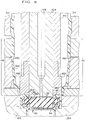
- an insertion assembly actuator 410 is operated to lower the plunger or crimp ring 422 against the bead 470. As illustrated in FIG. 6, this operation permanently deforms the bead against the top of the insert article to form the flange 478, similar to flange 38 in FIG. 1, over the top of the article 30 to retain the article on the container.
- the crimp ring or ram 422 deforms the bead against the insert article axially, in the general direction of the container body portion.
- a portion of the flange 478 is embedded in the peripheral groove 42 in the top surface of the insert article stopper 32.
- the molded embedment of the flange portion 480 in the stopper groove 42 provides a relatively stronger retention structure which even more effectively resists forces that might otherwise tend to dislodge the stopper 32 and/or its associated cup 34.
- the compression of the parison bead 470 with the crimp ring 422 against an inserted stopper or the like is highly effective in forming a retention flange or rim unitary with the container body.
- the retention flange can be formed with a desired thickness in a consistent manner. This is in contrast with prior unsuccessful attempts to form an effective retaining rim over the article 30 by merely pushing softened container body material radially inwardly over the top of the article with portions of a seal mold assembly or in a secondary operation. Such attempts do not provide a uniform rim of sufficient thickness to withstand the typical pull-out forces.
- the insert assembly actuators are operated to raise each crimp ring 422 to a retracted position, substantially to the position of the crimp ring 422 shown in FIG. 5.
- the mold assembly is opened (FIG. 7). This permits the formed, filled, and sealed packages 20 to be removed and/or conveyed out of the mold assembly by suitable conventional apparatus.
- the lower, main mold halves 302 and 304 are opened first.
- the seal mold halves 308 and 310 are subsequently opened along with the vacuum grippers 312 and 314. As the seal mold halves and grippers are opened, the partial vacuum drawn in those mold assembly components is terminated.
- an upper portion 200A of the parison extends from the upper, peripheral edge of the formed retention flange 478.
- This mold flash may be easily removed by conventional deflashing techniques.
- the bottom of the extending flash is connected to the flange 478 by only a very thin ring of material. This ring is easily broken during conventional deflashing operations.
- the package 20 is also initially formed with a downwardly projecting flash 482 as shown in FIG. 7.
- This flash can be similarly removed in conventional deflashing operations.
- the flash can be converted into a hanger, or the like, for package 20, if desired.
- FIGS. 8 and 9 illustrate the fabrication of the package in a related but somewhat different manner.
- the lower, main mold halves 302A and 304A do not have a shallow recess in the upper surface for receiving the insert article 30. Rather, the main mold halves 302A and 304A have a flat upper surface 464A against which the parison is urged by a blowing and filling mandrel during the blowing and filling of the container body portion.
- the lower portions of the seal mold halves 308A and 310A define a shoulder or recess 488A against which the parison is positioned when the insert article 30 is lowered into the seal mold halves by the insertion assembly pick-up tube 404.
- the seal mold halves 308A and 310A are spaced further than illustrated in FIG. 8 to provide a clearance around the vertical, peripheral, side surface of the insert article and accommodate initial placement of the article 30 within the seal mold halves. Subsequently, the seal mold halves 308A and 310A are moved closer together -- to the position illustrated in FIG. 8.
- the bead 470 is preferably formed against the top edge of the article 30.
- the insertion assembly actuator is operated to lower the crimp ring 422 against the bead 470 (FIG. 9). This permanently deforms the bead against the insert article 30 to form the flange 478 over a portion of the article 30.
- the crimp ring 422 is retracted upwardly, the main mold halves 302A and 304A are opened, and the seal mold halves 308A and 310A are opened along with the parison grippers 312 and 314 as partial vacuum is terminated.
- the package made by the form of the method and apparatus illustrated in FIGS. 8 and 9 is very similar to the package described heretofore.
- the insert article 30 is sealed entirely within the upper, seal mold halves into the neck portion of the produced container.
- a stopper such as the stopper 32
- a receiving cup 34 in conjunction with a rubber stopper can provide a higher strength retention structure in some cases, and isolates the stopper from the container contents.
- the thermoplastic material of the receiving cup 34 can be at least partially fused or otherwise united with the parison defining the container opening. Upon cooling, a substantially merged or unitary structure is formed from the cup and container upper wall.
- the outer peripheral surfaces of the receiving cup can be provided with ribs, fins, grooves, or the like, to further enhance sealing.
- the sealing of the insert article to the container can be enhanced with other techniques, such as ultrasonic heating.
- an adhesive-backed, foil seal can be applied to the outwardly facing surface of the retention flange 478, if desired, to completely cover the exterior surface of the insert article 30 with a protective covering.
Landscapes
- Engineering & Computer Science (AREA)
- Mechanical Engineering (AREA)
- Manufacturing & Machinery (AREA)
- Blow-Moulding Or Thermoforming Of Plastics Or The Like (AREA)
- Sealing Of Jars (AREA)
- Closures For Containers (AREA)
Applications Claiming Priority (2)
| Application Number | Priority Date | Filing Date | Title |
|---|---|---|---|
| US71664 | 1993-06-02 | ||
| US08/071,664 US5351462A (en) | 1993-06-02 | 1993-06-02 | Method and apparatus for installing an insert to seal a container |
Publications (3)
| Publication Number | Publication Date |
|---|---|
| EP0627298A2 true EP0627298A2 (fr) | 1994-12-07 |
| EP0627298A3 EP0627298A3 (fr) | 1995-06-28 |
| EP0627298B1 EP0627298B1 (fr) | 2000-03-22 |
Family
ID=22102790
Family Applications (1)
| Application Number | Title | Priority Date | Filing Date |
|---|---|---|---|
| EP94303923A Expired - Lifetime EP0627298B1 (fr) | 1993-06-02 | 1994-05-31 | Procédé et dispositif pour former une bride de maintien autour d'une fermeture de récipient |
Country Status (6)
| Country | Link |
|---|---|
| US (1) | US5351462A (fr) |
| EP (1) | EP0627298B1 (fr) |
| JP (1) | JP3658013B2 (fr) |
| CN (1) | CN1048936C (fr) |
| AU (1) | AU669288B2 (fr) |
| DE (1) | DE69423536T2 (fr) |
Families Citing this family (11)
| Publication number | Priority date | Publication date | Assignee | Title |
|---|---|---|---|---|
| DE4408394C2 (de) * | 1994-03-12 | 1999-06-24 | Bernd Hansen | Verpackungsmittel für Kontaktlinsen, insbesondere Einwegkontaktlinsen |
| DE4439231C1 (de) * | 1994-11-03 | 1996-04-25 | Bernd Hansen | Blasformverfahren zum Herstellen eines verschlossenen Behältnisses und nach diesem Verfahren hergestelltes Behältnis |
| US6092682A (en) * | 1996-04-23 | 2000-07-25 | Automatic Liquid Packaging, Inc. | Hermetically sealed container with closure insert |
| US5901865A (en) * | 1996-04-23 | 1999-05-11 | Automatic Liquid Packaging, Inc. | Hermetically sealed container with frangible web and locking lugs and method and apparatus for making same |
| US6098852A (en) * | 1999-01-27 | 2000-08-08 | Automatic Liquid Packaging, Inc. | Tip for liquid drop dispensing container |
| US6564531B2 (en) | 1999-04-07 | 2003-05-20 | Dtl Technology Limited Partnership | Blow molded container with memory shrink closure attachment and method of making the same |
| PT1497108E (pt) * | 2002-04-24 | 2006-11-30 | Werner Grabher | Lata provida de linhas de dobra e processo para fabrico da mesma |
| US7059104B2 (en) * | 2004-01-13 | 2006-06-13 | Jaws International, Ltd. | System for filling and closing fluid containing cartridges |
| EP2143543A1 (fr) * | 2008-07-07 | 2010-01-13 | Nestec S.A. | Dispositif et procédé de conditionnement de liquide alimentaire |
| FR3029468B1 (fr) * | 2014-12-09 | 2018-04-27 | Inergy Automotive Systems Research (Societe Anonyme) | Systeme pour vehicule automobile |
| CN117794659B (zh) | 2021-08-07 | 2025-04-08 | 布洛克怀斯工程公司 | 型坯成型机 |
Family Cites Families (13)
| Publication number | Priority date | Publication date | Assignee | Title |
|---|---|---|---|---|
| NL284490A (fr) * | 1961-10-25 | 1900-01-01 | ||
| DE1607950A1 (de) * | 1967-08-17 | 1970-09-24 | Bosch Gmbh Robert | Verfahren zum Verschliessen von Kunststoffflaschen |
| US3690088A (en) * | 1970-09-08 | 1972-09-12 | Dave Chapman | Method of packaging |
| US3851029A (en) * | 1973-03-07 | 1974-11-26 | Respiratory Care | Method for molding and sealing thermoplastic containers |
| US3919374A (en) * | 1973-04-23 | 1975-11-11 | Automatic Liquid Packaging | Method for blow molding a container having an auxiliary component formed as an integral part of it |
| US4176153A (en) * | 1978-02-10 | 1979-11-27 | Automatic Liquid Packaging, Inc. | Unitary, hermetically-sealed but pierceable dispensing container |
| DE3033821C2 (de) * | 1980-09-09 | 1982-09-09 | Gerhard 7166 Sulzbach-Laufen Hansen | Verfahren und Vorrichtung zum Herstellen eines Behälters aus einem heißsiegelbaren Kunststoffschlauch und durch das Verfahren und mittels der Vorrichtung hergestellter Behälter |
| DE3109500A1 (de) * | 1981-03-12 | 1982-10-07 | Repa Feinstanzwerk Gmbh, 7071 Alfdorf | Verfahren und werkzeug zur plastischen verformung von durch druck und waerme verformbarem material |
| US4596110A (en) * | 1981-08-26 | 1986-06-24 | Automatic Liquid Packaging, Inc. | Container with insert having a fully or partially encapsulating seal with a frangible web formed against said insert |
| US4707966A (en) * | 1981-08-26 | 1987-11-24 | Automatic Liquid Packaging, Inc. | Container with an encapsulated top insert and method and apparatus for making same |
| US4539172A (en) * | 1983-12-16 | 1985-09-03 | Baxter Travenol Laboratories, Inc. | Method of blowmolding a container having an integral inner dispensing outlet |
| FR2613707B1 (fr) * | 1987-04-07 | 1991-05-03 | Fuso Pharmaceutical Ind | Procede et dispositif d'obturation du goulot d'un recipient de transfusion en resine synthetique |
| DE68905881T2 (de) * | 1988-07-25 | 1993-08-19 | Cebal | Verfahren zum herstellen von beutelspendern, entsprechende teile und spender. |
-
1993
- 1993-06-02 US US08/071,664 patent/US5351462A/en not_active Expired - Lifetime
-
1994
- 1994-05-31 EP EP94303923A patent/EP0627298B1/fr not_active Expired - Lifetime
- 1994-05-31 DE DE69423536T patent/DE69423536T2/de not_active Expired - Lifetime
- 1994-05-31 CN CN94105496A patent/CN1048936C/zh not_active Expired - Lifetime
- 1994-06-02 JP JP14382694A patent/JP3658013B2/ja not_active Expired - Lifetime
- 1994-06-02 AU AU64510/94A patent/AU669288B2/en not_active Expired
Also Published As
| Publication number | Publication date |
|---|---|
| DE69423536T2 (de) | 2000-08-24 |
| EP0627298B1 (fr) | 2000-03-22 |
| CN1048936C (zh) | 2000-02-02 |
| JP3658013B2 (ja) | 2005-06-08 |
| EP0627298A3 (fr) | 1995-06-28 |
| AU6451094A (en) | 1994-12-08 |
| US5351462A (en) | 1994-10-04 |
| AU669288B2 (en) | 1996-05-30 |
| CN1097704A (zh) | 1995-01-25 |
| DE69423536D1 (de) | 2000-04-27 |
| JPH07187289A (ja) | 1995-07-25 |
Similar Documents
| Publication | Publication Date | Title |
|---|---|---|
| US6517768B1 (en) | Hermetically sealed container including a nozzle with a sealing bead | |
| US4176153A (en) | Unitary, hermetically-sealed but pierceable dispensing container | |
| US6168413B1 (en) | Apparatus for making a hermetically sealed container with frangible web and locking lugs | |
| US4178976A (en) | Unitary, hermetically-sealed but pierceable dispensing container | |
| EP0372011B1 (fr) | Recipient en plastique sous pression a valve ameliore | |
| US4671763A (en) | Container with a unitary but removable closure and method and apparatus therefor | |
| US4707966A (en) | Container with an encapsulated top insert and method and apparatus for making same | |
| US5921430A (en) | Blow molding sealed container system | |
| CA2708546C (fr) | Procede et dispositif de fabrication de recipients en materiau thermoplastique, et recipients ainsi fabriques | |
| US5351462A (en) | Method and apparatus for installing an insert to seal a container | |
| US4540542A (en) | Method for making a container with a unitary but removable closure | |
| GB2105250A (en) | Moulded containers and method of and apparatus for producing such containers | |
| EP0009381A1 (fr) | Récipient à poignée composé de deux éléments, moulé par soufflage, et procédé pour son moulage | |
| EP0713827A1 (fr) | Procédé de fabrication de récipients distributeurs de liquide | |
| CN1064630C (zh) | 带封闭插入物的密封容器 | |
| JPH0948478A (ja) | 積層剥離容器 | |
| AU676925B2 (en) | Collapsible package | |
| JP2558057B2 (ja) | 輸液用合成樹脂製容器口部閉塞方法 | |
| JP4253870B2 (ja) | 成形充填容器の製造方法 | |
| EP0244256B1 (fr) | Procédé pour la production de récipients tubulaires en matière plastique | |
| JPH02196621A (ja) | 把手付延伸中空容器の製造方法 | |
| JP3801281B2 (ja) | ボトルパック容器の成形装置 | |
| JPH0444895B2 (fr) |
Legal Events
| Date | Code | Title | Description |
|---|---|---|---|
| PUAI | Public reference made under article 153(3) epc to a published international application that has entered the european phase |
Free format text: ORIGINAL CODE: 0009012 |
|
| AK | Designated contracting states |
Kind code of ref document: A2 Designated state(s): CH DE FR GB IT LI SE |
|
| PUAL | Search report despatched |
Free format text: ORIGINAL CODE: 0009013 |
|
| AK | Designated contracting states |
Kind code of ref document: A3 Designated state(s): CH DE FR GB IT LI SE |
|
| 17P | Request for examination filed |
Effective date: 19951218 |
|
| 17Q | First examination report despatched |
Effective date: 19970120 |
|
| GRAG | Despatch of communication of intention to grant |
Free format text: ORIGINAL CODE: EPIDOS AGRA |
|
| GRAG | Despatch of communication of intention to grant |
Free format text: ORIGINAL CODE: EPIDOS AGRA |
|
| GRAG | Despatch of communication of intention to grant |
Free format text: ORIGINAL CODE: EPIDOS AGRA |
|
| GRAH | Despatch of communication of intention to grant a patent |
Free format text: ORIGINAL CODE: EPIDOS IGRA |
|
| GRAH | Despatch of communication of intention to grant a patent |
Free format text: ORIGINAL CODE: EPIDOS IGRA |
|
| GRAA | (expected) grant |
Free format text: ORIGINAL CODE: 0009210 |
|
| AK | Designated contracting states |
Kind code of ref document: B1 Designated state(s): CH DE FR GB IT LI SE |
|
| PG25 | Lapsed in a contracting state [announced via postgrant information from national office to epo] |
Ref country code: SE Free format text: THE PATENT HAS BEEN ANNULLED BY A DECISION OF A NATIONAL AUTHORITY Effective date: 20000322 Ref country code: FR Free format text: LAPSE BECAUSE OF FAILURE TO SUBMIT A TRANSLATION OF THE DESCRIPTION OR TO PAY THE FEE WITHIN THE PRESCRIBED TIME-LIMIT Effective date: 20000322 |
|
| REG | Reference to a national code |
Ref country code: CH Ref legal event code: EP |
|
| REF | Corresponds to: |
Ref document number: 69423536 Country of ref document: DE Date of ref document: 20000427 |
|
| ITF | It: translation for a ep patent filed | ||
| EN | Fr: translation not filed | ||
| REG | Reference to a national code |
Ref country code: CH Ref legal event code: NV Representative=s name: E. BLUM & CO. PATENTANWAELTE |
|
| PLBE | No opposition filed within time limit |
Free format text: ORIGINAL CODE: 0009261 |
|
| STAA | Information on the status of an ep patent application or granted ep patent |
Free format text: STATUS: NO OPPOSITION FILED WITHIN TIME LIMIT |
|
| 26N | No opposition filed | ||
| REG | Reference to a national code |
Ref country code: GB Ref legal event code: IF02 |
|
| REG | Reference to a national code |
Ref country code: CH Ref legal event code: PFA Owner name: AUTOMATIC LIQUID PACKAGING, INC. Free format text: AUTOMATIC LIQUID PACKAGING, INC.#2200 WEST LAKE SHORE DRIVE#WOODSTOCK ILLINOIS 60098 (US) -TRANSFER TO- AUTOMATIC LIQUID PACKAGING, INC.#2200 WEST LAKE SHORE DRIVE#WOODSTOCK ILLINOIS 60098 (US) |
|
| PGFP | Annual fee paid to national office [announced via postgrant information from national office to epo] |
Ref country code: GB Payment date: 20130529 Year of fee payment: 20 Ref country code: CH Payment date: 20130514 Year of fee payment: 20 Ref country code: DE Payment date: 20130529 Year of fee payment: 20 |
|
| PGFP | Annual fee paid to national office [announced via postgrant information from national office to epo] |
Ref country code: IT Payment date: 20130515 Year of fee payment: 20 |
|
| REG | Reference to a national code |
Ref country code: DE Ref legal event code: R071 Ref document number: 69423536 Country of ref document: DE |
|
| REG | Reference to a national code |
Ref country code: CH Ref legal event code: PL |
|
| REG | Reference to a national code |
Ref country code: GB Ref legal event code: PE20 Expiry date: 20140530 |
|
| PG25 | Lapsed in a contracting state [announced via postgrant information from national office to epo] |
Ref country code: GB Free format text: LAPSE BECAUSE OF EXPIRATION OF PROTECTION Effective date: 20140530 |
|
| PG25 | Lapsed in a contracting state [announced via postgrant information from national office to epo] |
Ref country code: DE Free format text: LAPSE BECAUSE OF EXPIRATION OF PROTECTION Effective date: 20140603 |