EP0628783B2 - Système d'actionnement pour gouverne aérodynamique et systèmes pour le pilotage d'aéronefs - Google Patents
Système d'actionnement pour gouverne aérodynamique et systèmes pour le pilotage d'aéronefs Download PDFInfo
- Publication number
- EP0628783B2 EP0628783B2 EP19940401101 EP94401101A EP0628783B2 EP 0628783 B2 EP0628783 B2 EP 0628783B2 EP 19940401101 EP19940401101 EP 19940401101 EP 94401101 A EP94401101 A EP 94401101A EP 0628783 B2 EP0628783 B2 EP 0628783B2
- Authority
- EP
- European Patent Office
- Prior art keywords
- steering
- aerodynamic control
- control surfaces
- airborne vehicle
- positions
- Prior art date
- Legal status (The legal status is an assumption and is not a legal conclusion. Google has not performed a legal analysis and makes no representation as to the accuracy of the status listed.)
- Expired - Lifetime
Links
- 230000004913 activation Effects 0.000 claims description 12
- 230000007935 neutral effect Effects 0.000 claims description 8
- 230000000694 effects Effects 0.000 description 3
- 238000006073 displacement reaction Methods 0.000 description 2
- 230000003213 activating effect Effects 0.000 description 1
- 230000002730 additional effect Effects 0.000 description 1
- 230000032683 aging Effects 0.000 description 1
- 238000012550 audit Methods 0.000 description 1
- 230000001419 dependent effect Effects 0.000 description 1
- 238000010586 diagram Methods 0.000 description 1
- 230000002427 irreversible effect Effects 0.000 description 1
- 238000004519 manufacturing process Methods 0.000 description 1
- 230000002123 temporal effect Effects 0.000 description 1
Images


Classifications
-
- F—MECHANICAL ENGINEERING; LIGHTING; HEATING; WEAPONS; BLASTING
- F42—AMMUNITION; BLASTING
- F42B—EXPLOSIVE CHARGES, e.g. FOR BLASTING, FIREWORKS, AMMUNITION
- F42B10/00—Means for influencing, e.g. improving, the aerodynamic properties of projectiles or missiles; Arrangements on projectiles or missiles for stabilising, steering, range-reducing, range-increasing or fall-retarding
- F42B10/60—Steering arrangements
- F42B10/62—Steering by movement of flight surfaces
- F42B10/64—Steering by movement of flight surfaces of fins
Definitions
- the present invention relates to an actuation system for aerodynamic control systems, as well as systems for piloting aircraft piloted in pairs by aerodynamic control surfaces, comprising at least such an actuation system.
- the object of the present invention is to provide an actuation system simple, inexpensive and very slightly aging, which is susceptible meet the requirements mentioned above.
- the switching of the aerodynamic control surface from one of its stable active positions to the other is obtained simply by activating said electromagnetic coils, which causes a displacement of the movable pallet causing the switching of said aerodynamic control surface.
- document GB-A-1 057 863 describes a system actuation to bring an aerodynamic control surface into either of two active and stable positions, said aerodynamic control surface being rotatably mounted on a fixed support and said system comprising a single electromagnetic coil associated with said control surface, arranged on said fixed support and acting directly on said rudder (without interposition of pallet) to make it turn against the action of a spring, so that said control surface can take (exclusively, without neutral position) either of two extreme positions.
- the elements constituting said actuation system according to the present invention are few and of a limited cost. Therefore, on the one hand the manufacturing price of the system actuation according to the invention is low and, on the other hand, the volume of the actuation system is extremely small, which is very advantageous for its use on small aircraft, for example example of light missiles.
- said movable element consists of a shaft rotary.
- said actuation system according to the invention has high torque and response time.
- the present invention also relates to a system for piloting an aircraft piloted in pairs by at least two aerodynamic control surfaces, said control system comprising at least one system such as that described above.
- the invention relates, more particularly, to a control system of an aircraft in autorotation comprising two aerodynamic control surfaces arranged symmetrically with respect to the body of the latter.
- This piloting system can in particular be used on multi-mission missiles and light anti-mites, which are characterized by high speed and low mass after launch. Efficient torque steering does not requires only small aerodynamic control surfaces.
- Each of said aerodynamic control surfaces can be actuated by an individual actuation system according to the invention and said aerodynamic control surfaces are controlled, synchronously, symmetrically with respect to the body of the aircraft, by simultaneous activation of a coil of each of said individual actuation systems.
- control surfaces are actuated by a common actuation system, said system common actuation comprising a movable element additional identical to said mobile and integral element of said pallet in a symmetrical position by relative to that of said movable member, said movable member bearing one of said aerodynamic control surfaces and said additional movable member carrying the other said aerodynamic control surfaces.
- This control system is particularly suitable very small aircraft, in particular mini missiles, whose reduced volume does not allow the arrangement of several actuation systems, el including aerodynamic control surfaces of restricted surface are subject to relatively small forces and can therefore be operated by a single system actuating.
- Pilot systems with one or two systems actuators, such as those described above, and comprising two aerodynamic control surfaces with two stable positions each, symmetrically operated synchronously, are likely to take one either of two riding positions, depending on the common stable position in which are located said aerodynamic control surfaces.
- the desired steering force is easily obtained and this simply by putting the system of piloting, for respective durations more or less long, in either of these riding positions.
- F1 control value 2f / ⁇
- the previous switching mode has a downside when looking for strength very low steering.
- the actuation system allowing switching has a time threshold, corresponding to its response time. Therefore, it is impossible to obtain a corresponding 2S angle at a duration below this time threshold.
- the present invention also relates to a system piloting an aircraft with four control surfaces aerodynamics arranged around said aircraft evenly spaced.
- such a control system which is particularly suitable for a large air-to-ground missile or a planing bomb with limited maneuver is remarkable in that the opposing gouvemes are identical and in that each of them is actuated by a compliant individual actuation system to the invention.
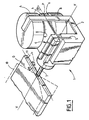
- Figure 1 is a partial perspective view of a actuation system according to the invention.
- Figure 2 schematically shows the system piloting an aircraft, comprising two control surfaces aerodynamics powered by two systems separate actuators.
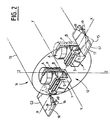
- Figure 3 schematically shows the system piloting an aircraft, comprising two control surfaces aerodynamics powered by the same system actuating.
- Figure 4 illustrates the generation of a lateral force piloting, according to a first piloting principle.
- Figure 5 illustrates the generation of a lateral force piloting, according to a second piloting principle.
- Figure 6 is the block diagram of the system piloting an aircraft with four control surfaces aerodynamic.
- the actuation system 1 is intended to operate an aerodynamic control surface G partially shown and schematically in this figure.
- said actuation system 1 has two electromagnetic coils identical A and B arranged opposite each other on a fixed support 2, which can be fixed on the body of a aircraft (not shown). Said coils A and B are can be activated independently, via a control system (not shown).
- Said actuation system 1 also comprises a movable pallet P fixed elastically by one of its ends 4 on the fixed support 2, via a leaf spring 5 secured to both of said end 4 and of said support 2.
- said blade of spring 5 is embedded by its opposite ends, at both in said fixed support 2 and in the end 4 of the P pallet.
- the other (free) end 6 of the P pallet is disposed between said coils A and B.
- a mobile element in this case a rotary shaft 7, is secured laterally to said pallet P at the end 4 of the latter, coaxially to the X-X axis.
- Said rotary shaft 7 carries the aerodynamic control surface G arranged parallel to the pallet P and shown in solid lines in its neutral position in Figure 1.
- control surface G is integral with the displacement of the free end 6 of the pallet P between coils A and B.
- the actuation system 1 can be used in a control system 12 of a aircraft 14 in autorotation around its Y-Y axis, of which is shown in Figure 2, partially and so schematically, the body 13.
- Said aircraft 14 is piloted in torque by two aerodynamic control surfaces G1 and G2 identical, arranged symmetrically with respect to to the Y-Y axis.
- Each of said aerodynamic control surfaces G1 and G2 is actuated by an actuation system 1 individual, and this synchronously, from so that said control surfaces are always in the same piloting plan.
- the coils A of each of the two actuation systems 1 are activated at the same time.
- coils B is true for coils B.
- control system 12 Depending on whether the control system 12 is located in either of these driving positions, it generates two steering forces of the same module, directed in the same direction Z-Z (perpendicular to the directions X-X and Y-Y) but in opposite directions.
- control system 20 comprises a single actuation system 1 for actuating the two aerodynamic control surfaces G1 and G2.
- the piloting of the aircraft 14 in autorotation is carried out in the same way for the two piloting systems 12 and 20 described above.
- the piloting system 12 or 20 is successively switched to its two piloting positions, thus generating at all times a piloting force of module f , of direction ZZ, and whose direction depends, at a given time, from the steering position used at that time.
- the control system 12 or 20 is kept in a first position of piloting for a period corresponding to an angle 2S of a circle C, representing the duration of a rotation turn of the aircraft and then is switched to the other position piloting for the rest of the duration of the said lap of rotation.
- Said first piloting position generates, at successive instants, on the circle C, along the circular arc defined by the angle 2S, radial forces of the same module f (as represented at points 21), while that the second piloting position generates piloting forces of the same module f but of opposite direction (as shown at points 22).
- this driving force F1 always remains greater than a minimum force.
- the control system 12 or 20 is switched in the same riding position for two durations corresponding respectively at two angles 2S1 and 2S2 on circle C and defined so these angles 2S1 and 2S2 are opposite and have the same L-L bisector.
- This second steering principle is particularly suitable for obtaining module driving forces F2 restricted, since it is possible to make the difference IsinS1-sinS2
- the actuation system 1 can also be used in a control system 25, as shown diagrammatically in FIG. 6, to fly relatively heavy aircraft, for example a large air-to-ground missile or a maneuvering bomb limited, through four control surfaces aerodynamics G3, G4, G5 and G6.
- Said aerodynamic control surfaces G3, G4, G5 and G6, each actuated by an actuation system 1 individual, are arranged around the aircraft (not shown), being each time removed from 90 °, so that, on the one hand, the aerodynamic control surfaces G3 and G5 which are identical and, on the other hand, the aerodynamic control surfaces G4 and G6 which are identical, are arranged symmetrically with respect to to the axis of said aircraft.
- the piloting of said aircraft is carried out by modifying activation of the electromagnetic coils A and B of different actuation systems 1, and therefore the position corresponding aerodynamic control surfaces.
Landscapes
- Physics & Mathematics (AREA)
- Fluid Mechanics (AREA)
- Engineering & Computer Science (AREA)
- General Engineering & Computer Science (AREA)
- Control Of Position, Course, Altitude, Or Attitude Of Moving Bodies (AREA)
- Details Of Aerials (AREA)
- Train Traffic Observation, Control, And Security (AREA)
- Braking Arrangements (AREA)
Description
- une palette mobile, dont l'une des extrémités est fixée élastiquement audit support fixe par l'intermédiaire d'une lame de ressort de sorte que, en position neutre de la gouverne, ladite palette mobile et ladite lame de ressort sont orthogonales, et dont l'autre extrémité est disposée entre lesdites bobines et est susceptible d'être attirée par chacune desdites bobines ; et
- un élément mobile solidaire de ladite palette et portant ladite gouverne aérodynamique.
- dans l'une desdites positions de pilotage pendant une durée correspondant à un angle 2S d'un cercle représentant la durée d'un tour de rotation de l'aéronef ; et
- dans l'autre position de pilotage pendant le reste dudit tour de rotation, l'angle 2S vérifiant la relation |sinS|=(π/2f).F1 et comportant comme bissectrice ladite direction définie.
- dans l'une desdites positions de pilotage pendant deux périodes non successives correspondant respectivement à deux angles 2S1 et 2S2 d'un cercle représentant la durée d'un tour de rotation de l'aéronef ; et
- dans l'autre position de pilotage pendant le reste dudit tour de rotation, lesdits angles S1 et S2 étant opposés, comportant comme même bissectrice ladite direction définie et vérifiant la relation IsinS1-sinS2I=(π/2f).F2.
- un système de guidage, déterminant les ordres de roulis, tangage et lacet ; et
- un calculateur, recevant lesdits ordres, et déterminant l'activation des différentes bobines électromagnétiques.
- dans la position active stable 10 qui fait un angle +Θ par rapport à la position neutre, lorsque la bobine A est activée et que l'extrémité libre 6 de la palette P se trouve au contact de celle-ci ; et
- dans la position active stable 11 qui fait un angle -Θ par rapport à la position neutre, lorsque la bobine B est activée et que l'extrémité libre 6 se trouve au contact de cette dernière.
- une première position de pilotage, lorsque les palettes P sont au contact des bobines A et qu'alors les gouvernes aérodynamiques G1 et G2 se trouvent respectivement dans des positions 15 et 16 partiellement représentées en traits interrompus sur la figure 2 et faisant un angle +Θ avec la position médiane représentée ; et
- une seconde position de pilotage, lorsque les palettes P sont au contact des bobines B et qu'alors les gouvernes aérodynamiques G1 et G2 se trouvent respectivement dans des positions 17 et 18 partiellement représentées en traits interrompus et faisant un angle -Θ avec la position médiane représentée.
- une première position de pilotage, lorsque la palette P est au contact de la bobine A et que les gouvernes aérodynamiques G1 et G2 se trouvent respectivement dans les positions 15 et 16; et
- une seconde position de pilotage, lorsque la palette P est au contact de la bobine B et que les gouvernes aérodynamiques G1 et G2 se trouvent alors respectivement dans les positions 17 et 18.
- un système de guidage 27 déterminant les ordres de roulis, de tangage et de lacet ; et
- un calculateur 28, recevant lesdits ordres par l'intermédiaire d'une liaison 29, déterminant l'activation des bobines électromagnétiques A et B des systèmes d'actionnement 1 associés à chacune des gouvernes aérodynamiques G3, G4, G5 et G6, et commandant lesdites bobines A et B par l'intermédiaire de liaisons 30 à 33.
Claims (9)
- Système d'actionnement (1) pour amener une gouverne aérodynamique (G) dans l'une ou l'autre de deux positions actives, stables et opposées l'une de l'autre par rapport à une position neutre, ladite gouverne aérodynamique (G) étant montée rotative sur un support fixe (2), ledit système d'actionnement (1) comportant deux bobines électromagnétiques (A, B) agencées sur ledit support fixe (2), l'une en regard de l'autre, pour faire tourner ladite gouverne aérodynamique à l'encontre de l'action de moyens élastiques,
caractérisé en ce que ledit système d'actionnement (1) comporte de plus :une palette mobile (P), dont l'une (4) des extrémités est fixée élastiquement audit support fixe (2) par l'intermédiaire d'une lame de ressort (5) de sorte que, en position neutre de la gouverne, ladite palette mobile (P) et ladite lame de ressort (5) sont orthogonales, et dont l'autre extrémité (6) est disposée entre lesdites bobines (A, B) et est susceptible d'être attirée par chacune desdites bobines ; etun élément mobile (7) solidaire de ladite palette (P) et portant ladite gouverne aérodynamique (G). - Système selon la revendication 1,
caractérisé en ce que ledit élément mobile est constitué d'un arbre rotatif (7). - Système pour le pilotage d'un aéronef piloté en couple par au moins deux gouvernes aérodynamiques (G1, G2, G3, G4, G5, G6),
caractérisé en ce qu'il comporte au moins un système d'actionnement (1) selon l'une des revendications 1 et 2. - Système pour le pilotage d'un aéronef en autorotation, comportant deux gouvernes aérodynamiques identiques (G1, G2) agencées symétriquement par rapport au corps de ce dernier, selon la revendication 3,
caractérisé en ce que chacune desdites gouvernes aérodynamiques (G1, G2) est actionnée par un système d'actionnement (1) individuel et en ce que lesdites gouvernes aérodynamiques (G1, G2) sont commandées, de façon synchrone, symétriquement par rapport au corps de l'aéronef, par l'activation simultanée d'une bobine de chacun desdits systèmes d'actionnement individuels. - Système pour le pilotage d'un aéronef en autorotation, comportant deux gouvernes aérodynamiques identiques (G1, G2) agencées symétriquement par rapport au corps de ce dernier, selon la revendication 3,
caractérisé en ce que lesdites gouvernes (G1, G2) sont actionnées par un système d'actionnement (1) commun, ledit système d'actionnement (1) commun comportant un élément mobile supplémentaire (7) identique audit élément mobile (7) et solidaire de ladite palette dans une position symétrique par rapport à celle dudit élément mobile, ledit élément mobile portant l'une desdites gouvernes aérodynamiques et ledit élément mobile supplémentaire portant l'autre desdites gouvernes aérodynamiques. - Système selon l'une des revendications 4 ou 5, pour le pilotage d'un aéronef, comportant deux gouvernes aérodynamiques, à deux positions actives stables chacune, actionnées symétriquement de façon synchrone et mettant, en fonction de la position stable commune dans laquelle elles se trouvent, ledit système de pilotage dans l'une de deux positions de pilotage, le module de la force pilotage étant égal à f dans chacune desdites positions de pilotage,
caractérisé en ce que, pour obtenir sur un tour de rotation de l'aéronef une force moyenne de pilotage de module F1 dirigée selon une direction définie (Ox), il est successivement commuté :dans l'une desdites positions de pilotage pendant une durée correspondant à un angle 2S d'un cercle (C) représentant la durée d'un tour de rotation de l'aéronef ; etdans l'autre position de pilotage pendant le reste dudit tour de rotation, l'angle 2S vérifiant la relation |sinS| = (π/2f).F1 et comportant comme bissectrice ladite direction définie (Ox). - Système selon l'une des revendications 4 ou 5, pour le pilotage d'un aéronef, comportant deux gouvernes aérodynamiques à deux positions actives stables chacune, actionnées symétriquement de façon synchrone, et mettant, en fonction de la position stable dans laquelle elles se trouvent, ledit système dans l'une de deux positions de pilotage, le module de la force de pilotage étant égal à f dans chacune desdites positions de pilotage,
caractérisé en ce que, pour obtenir sur un tour de rotation de l'aéronef une force moyenne de pilotage de module F2 dirigée selon une direction définie (L-L), il est successivement commuté :dans l'une desdites positions de pilotage pendant deux périodes non successives correspondant respectivement à deux angles 2S1 et 2S2 d'un cercle (C) représentant la durée d'un tour de rotation de l'aéronef ; etdans l'autre position de pilotage pendant le reste dudit tour de rotation, lesdits angles S1 et S2 étant opposés, comportant comme même bissectrice ladite direction définie (L-L) et vérifiant la relation | sinS1-sinS2| = (π/2f).F2. - Système selon la revendication 3, pour le pilotage d'un aéronef, comportant quatre gouvernes aérodynamiques (G3, G4, G5, G6) agencées de façon uniformément espacée autour dudit aéronef,
caractérisé en ce que les gouvernes à chaque fois opposées sont identiques et en ce que chacune desdites gouvernes est actionnée par un système d'actionnement (1) individuel. - Système pour le pilotage d'un aéronef selon la revendication 8,
caractérisé en ce qu'il est muni d'un dispositif de commande (26) destiné à commander l'activation des bobines électromagnétiques (A, B) des différents systèmes d'actionnement individuels, comportant :un système de guidage (27), déterminant les ordres de roulis, tangage et lacet ; etun calculateur (28), recevant lesdits ordres, et déterminant l'activation des différentes bobines électromagnétiques.
Applications Claiming Priority (2)
| Application Number | Priority Date | Filing Date | Title |
|---|---|---|---|
| FR9306779 | 1993-06-07 | ||
| FR9306779A FR2706200B1 (fr) | 1993-06-07 | 1993-06-07 | Système d'actionnement pour gouverne aérodynamique et systèmes pour le pilotage d'aéronefs, comportant au moins un tel système d'actionnement. |
Publications (3)
| Publication Number | Publication Date |
|---|---|
| EP0628783A1 EP0628783A1 (fr) | 1994-12-14 |
| EP0628783B1 EP0628783B1 (fr) | 1998-08-12 |
| EP0628783B2 true EP0628783B2 (fr) | 2003-08-27 |
Family
ID=9447817
Family Applications (1)
| Application Number | Title | Priority Date | Filing Date |
|---|---|---|---|
| EP19940401101 Expired - Lifetime EP0628783B2 (fr) | 1993-06-07 | 1994-05-18 | Système d'actionnement pour gouverne aérodynamique et systèmes pour le pilotage d'aéronefs |
Country Status (5)
| Country | Link |
|---|---|
| EP (1) | EP0628783B2 (fr) |
| DE (1) | DE69412366T3 (fr) |
| ES (1) | ES2120584T5 (fr) |
| FR (1) | FR2706200B1 (fr) |
| NO (1) | NO307434B1 (fr) |
Families Citing this family (1)
| Publication number | Priority date | Publication date | Assignee | Title |
|---|---|---|---|---|
| WO2010005350A1 (fr) | 2008-07-07 | 2010-01-14 | Saab Ab | Mécanisme de volet de direction |
Family Cites Families (5)
| Publication number | Priority date | Publication date | Assignee | Title |
|---|---|---|---|---|
| US3204894A (en) * | 1962-06-29 | 1965-09-07 | Bofors Ab | Roll stabilizing system for an airborne device |
| DE1298912B (de) * | 1965-12-10 | 1969-07-03 | Messerschmitt Boelkow Blohm | Schubvektorsteuerung fuer einen raketengetriebenen Flugkoerper mit mindestens einem Strahlablenker |
| SE408323B (sv) * | 1976-06-08 | 1979-06-05 | Bofors Ab | Styranordning for en ballistisk enhet |
| US4274610A (en) * | 1978-07-14 | 1981-06-23 | General Dynamics, Pomona Division | Jet tab control mechanism for thrust vector control |
| DE3606835C2 (de) * | 1986-03-03 | 1997-03-27 | Diehl Gmbh & Co | Lenkeinrichtung für Projektile |
-
1993
- 1993-06-07 FR FR9306779A patent/FR2706200B1/fr not_active Expired - Fee Related
-
1994
- 1994-05-18 EP EP19940401101 patent/EP0628783B2/fr not_active Expired - Lifetime
- 1994-05-18 DE DE1994612366 patent/DE69412366T3/de not_active Expired - Lifetime
- 1994-05-18 ES ES94401101T patent/ES2120584T5/es not_active Expired - Lifetime
- 1994-06-06 NO NO942092A patent/NO307434B1/no not_active IP Right Cessation
Also Published As
| Publication number | Publication date |
|---|---|
| NO942092D0 (no) | 1994-06-06 |
| DE69412366D1 (de) | 1998-09-17 |
| ES2120584T3 (es) | 1998-11-01 |
| DE69412366T3 (de) | 2004-03-25 |
| FR2706200B1 (fr) | 1995-08-11 |
| NO307434B1 (no) | 2000-04-03 |
| NO942092L (no) | 1994-12-08 |
| EP0628783A1 (fr) | 1994-12-14 |
| FR2706200A1 (fr) | 1994-12-16 |
| ES2120584T5 (es) | 2004-04-16 |
| EP0628783B1 (fr) | 1998-08-12 |
| DE69412366T2 (de) | 1999-03-04 |
Similar Documents
| Publication | Publication Date | Title |
|---|---|---|
| EP1002716B1 (fr) | Procédé et dispositif de pilotage de l'attitude d'un satellite | |
| EP0778201B1 (fr) | Procédé de commande d'attitude d'un satellite en orbite basse, a acquisition solaire | |
| EP3168149A1 (fr) | Drone ayant un support de propulsion couple | |
| EP1550837A1 (fr) | Dispositif de déploiement et d'entrainement de gouvernes d'un projectile | |
| EP2660154A2 (fr) | Système de propulsion pour contrôle d'orbite et contrôle d'attitude de satellite | |
| CA2640521C (fr) | Systeme de commande electrique pour une gouverne de direction d'un avion | |
| EP2666723A1 (fr) | Système de propulsion pour contrôle d'orbite et contrôle d'attitude de satellite | |
| FR2643609A1 (fr) | Dispositif propulseur pour vehicule sous-marin | |
| EP1914815B1 (fr) | Tourelle d'orientation deux axes avec motorisation piezo electrique | |
| EP1772698B1 (fr) | Dispositif d'entraînement de gouvernes de projectile | |
| EP3144228A1 (fr) | Actionneur gyroscopique a double guidage cardan, element de suspension et element de butee | |
| CA2096398A1 (fr) | Satellite geodesique de faible masse a retroreflecteur a correction d'aberration de vitesse | |
| EP0628783B2 (fr) | Système d'actionnement pour gouverne aérodynamique et systèmes pour le pilotage d'aéronefs | |
| EP0277445B1 (fr) | Projectile comportant des sous-projectiles à zone d'efficacité prédéfinie | |
| EP0101333B1 (fr) | Procédé et dispositif de commande d'attitude pour satellite géosynchrone | |
| FR2785381A1 (fr) | Procede et dispositif pour permettre l'execution, par un vehicule, d'un virage rapide dans un milieu fluide | |
| EP0161962A1 (fr) | Système d'arme et missile pour la destruction structurale d'une cible aérienne au moyen d'une charge focalisée | |
| EP1093561B1 (fr) | Dispositif d'autoprotection passive pour engin mobile tel qu'un helicoptere | |
| FR2964946A1 (fr) | Petit engin volant sans pilote | |
| EP1569847B1 (fr) | Procede de pilotage solaire de vehicule spatial | |
| EP0626556B1 (fr) | Système de pilotage d'un aéronef par interception du jet propulsif | |
| EP0316216B1 (fr) | Dispositif de stabilisation gyroscopique pour un organe de manoeuvre de projectile | |
| EP1600728A1 (fr) | Engin volant pour l'observation du sol | |
| EP0385878A1 (fr) | Système de guidage d'un vecteur par jets de gaz continus | |
| EP1635485B1 (fr) | Procédé de transmission optique entre un terminal embarqué sur un engin spatial et un terminal distant, et engin spatial adapté pour un tel procédé |
Legal Events
| Date | Code | Title | Description |
|---|---|---|---|
| PUAI | Public reference made under article 153(3) epc to a published international application that has entered the european phase |
Free format text: ORIGINAL CODE: 0009012 |
|
| AK | Designated contracting states |
Kind code of ref document: A1 Designated state(s): BE CH DE ES GB IT LI NL PT SE |
|
| 17P | Request for examination filed |
Effective date: 19941229 |
|
| 17Q | First examination report despatched |
Effective date: 19960611 |
|
| GRAG | Despatch of communication of intention to grant |
Free format text: ORIGINAL CODE: EPIDOS AGRA |
|
| GRAG | Despatch of communication of intention to grant |
Free format text: ORIGINAL CODE: EPIDOS AGRA |
|
| GRAH | Despatch of communication of intention to grant a patent |
Free format text: ORIGINAL CODE: EPIDOS IGRA |
|
| GRAH | Despatch of communication of intention to grant a patent |
Free format text: ORIGINAL CODE: EPIDOS IGRA |
|
| GRAA | (expected) grant |
Free format text: ORIGINAL CODE: 0009210 |
|
| AK | Designated contracting states |
Kind code of ref document: B1 Designated state(s): BE CH DE ES GB IT LI NL PT SE |
|
| REG | Reference to a national code |
Ref country code: CH Ref legal event code: NV Representative=s name: JOHN P. MUNZINGER INGENIEUR-CONSEIL Ref country code: CH Ref legal event code: EP |
|
| GBT | Gb: translation of ep patent filed (gb section 77(6)(a)/1977) |
Effective date: 19980814 |
|
| REF | Corresponds to: |
Ref document number: 69412366 Country of ref document: DE Date of ref document: 19980917 |
|
| REG | Reference to a national code |
Ref country code: ES Ref legal event code: FG2A Ref document number: 2120584 Country of ref document: ES Kind code of ref document: T3 |
|
| REG | Reference to a national code |
Ref country code: PT Ref legal event code: SC4A Free format text: AVAILABILITY OF NATIONAL TRANSLATION Effective date: 19980828 |
|
| PLBQ | Unpublished change to opponent data |
Free format text: ORIGINAL CODE: EPIDOS OPPO |
|
| PLBI | Opposition filed |
Free format text: ORIGINAL CODE: 0009260 |
|
| PLBF | Reply of patent proprietor to notice(s) of opposition |
Free format text: ORIGINAL CODE: EPIDOS OBSO |
|
| 26 | Opposition filed |
Opponent name: BOFORS MISSILES AB Effective date: 19990511 |
|
| PLBF | Reply of patent proprietor to notice(s) of opposition |
Free format text: ORIGINAL CODE: EPIDOS OBSO |
|
| REG | Reference to a national code |
Ref country code: GB Ref legal event code: IF02 |
|
| PLAW | Interlocutory decision in opposition |
Free format text: ORIGINAL CODE: EPIDOS IDOP |
|
| PLAW | Interlocutory decision in opposition |
Free format text: ORIGINAL CODE: EPIDOS IDOP |
|
| PLAW | Interlocutory decision in opposition |
Free format text: ORIGINAL CODE: EPIDOS IDOP |
|
| RAP2 | Party data changed (patent owner data changed or rights of a patent transferred) |
Owner name: AEROSPATIALE MATRA |
|
| PLAW | Interlocutory decision in opposition |
Free format text: ORIGINAL CODE: EPIDOS IDOP |
|
| NLT2 | Nl: modifications (of names), taken from the european patent patent bulletin |
Owner name: AEROSPATIALE MATRA |
|
| PUAH | Patent maintained in amended form |
Free format text: ORIGINAL CODE: 0009272 |
|
| STAA | Information on the status of an ep patent application or granted ep patent |
Free format text: STATUS: PATENT MAINTAINED AS AMENDED |
|
| 27A | Patent maintained in amended form |
Effective date: 20030827 |
|
| AK | Designated contracting states |
Designated state(s): BE CH DE ES GB IT LI NL PT SE |
|
| REG | Reference to a national code |
Ref country code: CH Ref legal event code: AEN Free format text: MAINTIEN DU BREVET DONT L'ETENDUE A ETE MODIFIEE |
|
| GBTA | Gb: translation of amended ep patent filed (gb section 77(6)(b)/1977) | ||
| NLR2 | Nl: decision of opposition |
Effective date: 20030827 |
|
| REG | Reference to a national code |
Ref country code: SE Ref legal event code: RPEO |
|
| REG | Reference to a national code |
Ref country code: PT Ref legal event code: PD4A Free format text: AEROSPATIALE MATRA FR Effective date: 20031028 |
|
| NLR3 | Nl: receipt of modified translations in the netherlands language after an opposition procedure | ||
| REG | Reference to a national code |
Ref country code: CH Ref legal event code: PFA Owner name: AEROSPATIALE MATRA Free format text: AEROSPATIALE SOCIETE NATIONALE INDUSTRIELLE#37, BOULEVARD DE MONTMORENCY#75781 PARIS CEDEX 16 (FR) -TRANSFER TO- AEROSPATIALE MATRA#37, BOULEVARD DE MONTMORENCY#75781 PARIS CEDEX 16 (FR) Ref country code: CH Ref legal event code: NV Representative=s name: CRONIN INTELLECTUAL PROPERTY |
|
| REG | Reference to a national code |
Ref country code: ES Ref legal event code: DC2A Date of ref document: 20031010 Kind code of ref document: T5 |
|
| REG | Reference to a national code |
Ref country code: CH Ref legal event code: PCAR Free format text: CRONIN INTELLECTUAL PROPERTY;CHEMIN DE PRECOSSY 31;1260 NYON (CH) |
|
| PGFP | Annual fee paid to national office [announced via postgrant information from national office to epo] |
Ref country code: CH Payment date: 20110513 Year of fee payment: 18 Ref country code: SE Payment date: 20110520 Year of fee payment: 18 Ref country code: PT Payment date: 20110504 Year of fee payment: 18 Ref country code: ES Payment date: 20110526 Year of fee payment: 18 |
|
| PGFP | Annual fee paid to national office [announced via postgrant information from national office to epo] |
Ref country code: NL Payment date: 20110524 Year of fee payment: 18 Ref country code: BE Payment date: 20110530 Year of fee payment: 18 Ref country code: GB Payment date: 20110523 Year of fee payment: 18 |
|
| PGFP | Annual fee paid to national office [announced via postgrant information from national office to epo] |
Ref country code: IT Payment date: 20110530 Year of fee payment: 18 Ref country code: DE Payment date: 20110511 Year of fee payment: 18 |
|
| REG | Reference to a national code |
Ref country code: PT Ref legal event code: MM4A Free format text: LAPSE DUE TO NON-PAYMENT OF FEES Effective date: 20121119 |
|
| BERE | Be: lapsed |
Owner name: *AEROSPATIALE MATRA Effective date: 20120531 |
|
| REG | Reference to a national code |
Ref country code: NL Ref legal event code: V1 Effective date: 20121201 |
|
| REG | Reference to a national code |
Ref country code: CH Ref legal event code: PL |
|
| REG | Reference to a national code |
Ref country code: SE Ref legal event code: EUG |
|
| GBPC | Gb: european patent ceased through non-payment of renewal fee |
Effective date: 20120518 |
|
| PG25 | Lapsed in a contracting state [announced via postgrant information from national office to epo] |
Ref country code: CH Free format text: LAPSE BECAUSE OF NON-PAYMENT OF DUE FEES Effective date: 20120531 Ref country code: LI Free format text: LAPSE BECAUSE OF NON-PAYMENT OF DUE FEES Effective date: 20120531 |
|
| PG25 | Lapsed in a contracting state [announced via postgrant information from national office to epo] |
Ref country code: BE Free format text: LAPSE BECAUSE OF NON-PAYMENT OF DUE FEES Effective date: 20120531 Ref country code: PT Free format text: LAPSE BECAUSE OF NON-PAYMENT OF DUE FEES Effective date: 20121119 Ref country code: IT Free format text: LAPSE BECAUSE OF NON-PAYMENT OF DUE FEES Effective date: 20120518 Ref country code: SE Free format text: LAPSE BECAUSE OF NON-PAYMENT OF DUE FEES Effective date: 20120519 |
|
| REG | Reference to a national code |
Ref country code: DE Ref legal event code: R119 Ref document number: 69412366 Country of ref document: DE Effective date: 20121201 |
|
| PG25 | Lapsed in a contracting state [announced via postgrant information from national office to epo] |
Ref country code: NL Free format text: LAPSE BECAUSE OF NON-PAYMENT OF DUE FEES Effective date: 20121201 |
|
| PG25 | Lapsed in a contracting state [announced via postgrant information from national office to epo] |
Ref country code: GB Free format text: LAPSE BECAUSE OF NON-PAYMENT OF DUE FEES Effective date: 20120518 |
|
| PG25 | Lapsed in a contracting state [announced via postgrant information from national office to epo] |
Ref country code: DE Free format text: LAPSE BECAUSE OF NON-PAYMENT OF DUE FEES Effective date: 20121201 |
|
| REG | Reference to a national code |
Ref country code: ES Ref legal event code: FD2A Effective date: 20130724 |
|
| PG25 | Lapsed in a contracting state [announced via postgrant information from national office to epo] |
Ref country code: ES Free format text: LAPSE BECAUSE OF NON-PAYMENT OF DUE FEES Effective date: 20120519 |