EP0629571B1 - Maschine zum automatischen Positionieren und Ausrichten von Behältern - Google Patents
Maschine zum automatischen Positionieren und Ausrichten von Behältern Download PDFInfo
- Publication number
- EP0629571B1 EP0629571B1 EP94500107A EP94500107A EP0629571B1 EP 0629571 B1 EP0629571 B1 EP 0629571B1 EP 94500107 A EP94500107 A EP 94500107A EP 94500107 A EP94500107 A EP 94500107A EP 0629571 B1 EP0629571 B1 EP 0629571B1
- Authority
- EP
- European Patent Office
- Prior art keywords
- containers
- openings
- annular
- machine
- container holder
- Prior art date
- Legal status (The legal status is an assumption and is not a legal conclusion. Google has not performed a legal analysis and makes no representation as to the accuracy of the status listed.)
- Expired - Lifetime
Links
- 230000002093 peripheral effect Effects 0.000 claims description 13
- 230000008878 coupling Effects 0.000 description 2
- 238000010168 coupling process Methods 0.000 description 2
- 238000005859 coupling reaction Methods 0.000 description 2
- 238000007599 discharging Methods 0.000 description 2
- 238000004519 manufacturing process Methods 0.000 description 2
- 238000009825 accumulation Methods 0.000 description 1
- 239000003638 chemical reducing agent Substances 0.000 description 1
- 238000006073 displacement reaction Methods 0.000 description 1
- 230000005484 gravity Effects 0.000 description 1
- 238000011084 recovery Methods 0.000 description 1
- 229920002994 synthetic fiber Polymers 0.000 description 1
Images



Classifications
-
- B—PERFORMING OPERATIONS; TRANSPORTING
- B65—CONVEYING; PACKING; STORING; HANDLING THIN OR FILAMENTARY MATERIAL
- B65G—TRANSPORT OR STORAGE DEVICES, e.g. CONVEYORS FOR LOADING OR TIPPING, SHOP CONVEYOR SYSTEMS OR PNEUMATIC TUBE CONVEYORS
- B65G47/00—Article or material-handling devices associated with conveyors; Methods employing such devices
- B65G47/02—Devices for feeding articles or materials to conveyors
- B65G47/04—Devices for feeding articles or materials to conveyors for feeding articles
- B65G47/12—Devices for feeding articles or materials to conveyors for feeding articles from disorderly-arranged article piles or from loose assemblages of articles
- B65G47/14—Devices for feeding articles or materials to conveyors for feeding articles from disorderly-arranged article piles or from loose assemblages of articles arranging or orientating the articles by mechanical or pneumatic means during feeding
- B65G47/1407—Devices for feeding articles or materials to conveyors for feeding articles from disorderly-arranged article piles or from loose assemblages of articles arranging or orientating the articles by mechanical or pneumatic means during feeding the articles being fed from a container, e.g. a bowl
- B65G47/1442—Devices for feeding articles or materials to conveyors for feeding articles from disorderly-arranged article piles or from loose assemblages of articles arranging or orientating the articles by mechanical or pneumatic means during feeding the articles being fed from a container, e.g. a bowl by means of movement of the bottom or a part of the wall of the container
- B65G47/1457—Rotating movement in the plane of the rotating part
-
- B—PERFORMING OPERATIONS; TRANSPORTING
- B65—CONVEYING; PACKING; STORING; HANDLING THIN OR FILAMENTARY MATERIAL
- B65G—TRANSPORT OR STORAGE DEVICES, e.g. CONVEYORS FOR LOADING OR TIPPING, SHOP CONVEYOR SYSTEMS OR PNEUMATIC TUBE CONVEYORS
- B65G2201/00—Indexing codes relating to handling devices, e.g. conveyors, characterised by the type of product or load being conveyed or handled
- B65G2201/02—Articles
- B65G2201/0235—Containers
- B65G2201/0244—Bottles
Definitions
- This invention relates to a machine intended for automatically positioning and continuously feeding containers, for example bottles or other hollow articles made from synthetic material, which may be of very different sizes and shapes. Taking into account that the speed of filling machines has increased with the passage of time it is therefore necessary to provide a positioning machine which has a sufficiently high rate of delivery of plastic bottles which are properly oriented and aligned to allow a high production filling machines or similar equipment to operate at its optimum capacity.
- Machines known to the applicant are the following grouped by the function they perform:
- the bottom of the machines and/or the rotatable disc or plane having the openings is, in general, inclined, though it can be constructed in the shape of a cone or frustum of a cone having a vertical axis, as this solution can be found in the state-of-the-art, and it appears disclosed, for example, in patent DE 277347 (Polte) and patent US 1,823,995 (Streby), which refers to machines of the same type as described above, in which case the inclined plane of the rotary element will by its slope and at the periphery move the containers downwardly defining a guiding duct which promotes the passage of the containers toward the openings associated with the falling chutes.
- the bottom plane according to the above background prior art, is provided with a rotation movement in the same or opposite sense to the openings for collecting and conveying the containers.
- the patent GB 1,558,379 which relates to a machine as the mentioned in the patent AU 499,038 discloses another example of a machine having a double row of openings, located at two levels on the periphery of the rotary disc forming the bottom of the machine, each in correspondence with a series of discharge chutes one for each of said openings.
- Patent US 4,979,607 (FOGG) likewise discloses a machine of these characteristics with two radially spaced concentric rows of coplanar openings on the periphery of a rotatable disc which communicate with two arrangements of concentric upright discharge chutes, radially spaced.
- the containers fall in the discharge chutes and are supported by their bottom on a second fixed plane, intermediate to said chutes receiving in drop the containers with a development in an arch under 360 degrees, forming thereon two concentric rows, and from said second intermediate plane they pass to a single row formed on a third parallel, fixed plane, at a lower level, to which they have access through discharge chutes alternatively upright and inclined located under the second mentioned intermediate plane provided with an interruption to facilitate said transfer.
- the disclosed machines have the following main problems:
- One object of this invention is to provide a machine of the above disclosed type which overcomes the above mentioned drawbacks.
- said rows of openings are distributed along the peripheral area of the hopper and under the edge of the bottom plane thereof, in such a way that in several areas perfectly delimited only one of said rows remains open allowing to admit containers, while the remaining rows are closed.
- covering means such as walls separate said rows of openings in several non adjacent areas, spaced along said peripheral portion of said bottom, at each of them only one portion of a predetermined length of one of said annular rows of openings is open allowing the passage of the container therein, while the remaining annular rows of openings are covered-up.
- the machine of this invention includes two concentric rows of openings having a fixed size and arranged in a quincunx disposition, with open portions thereof distributed along two differentiated areas, in diametral opposition.
- Deflecting panels are located within the hopper which extend close to the end of each open area of a row, in the sense of confronting the rotation of the rotary bottom plane, separating the loading areas of each of the rows.
- Another characteristic of the invention consists in that under the two rows of mentioned concentric openings, there exists a single arrangement in annular row of single discharge chutes, independently removable for receiving and transferring the containers, correctly oriented, the said discharge chutes respectively communicating in an alternate and successive form with an opening of the internal row and with an opening of the external row the first ones having an upper inclined portion which extends at the rear of the second ones, whose discharge chutes receive in drop the containers of the two rows of openings and align them along a fixed bottom from which they are evacuated by an exit conveyor.
- the machine according to the invention is characterized in that it comprises a plurality of concentric, annular elements, arranged at different levels, according to successively increasing diameters, each in relation with its immediate upper one, provided with openings having fixed sizes and carrying a plurality of exchangeable hollow frame-shaped container holders having recesses therein for receiving and holding containers in a lying position, like the ones described in my pending EP patent application 578602.
- the cited annular elements are linked to a fixed central column by means driving them in simultaneous rotation. Extending below each of these annular elements there is a fixed shelf for supporting containers in a lying position in said recesses during movement of said container holders; and under each container holder receiving a container there will exist a corresponding discharge chute.
- the discharge chutes adopt a structure as a drum-like annular arrangement and they are independently exchangeable securing the transfer, level to level of the containers of each recess toward a single annular plane which re-groups, in a single row, the whole of the containers put upright.
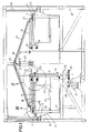
- Fig. 1 is a vertical cross-sectional view of a machine according with the invention.
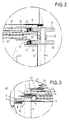
- Fig. 2 is an enlarged detail with cross-section of the driving members of the rotatable annular elements of the machine represented in the Fig. 1.
- Fig. 3 is a second enlarged detail, of the external portion of mentioned rotatable annular elements.
- Fig. 4 is a top plan view showing a preferred structure showing the connection of the annular elements to the driving means.
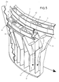
- Fig. 5 is a fragmented perspective view, at larger scale, illustrating the structure of an embodiment of the discharge chutes which are convergent on a single alignment row above a fixed bottom.
- Fig 6 is a perspective view showing an alternative embodiment of the machine according to the invention provided with rotatable annular elements which are coplanar.
- Fig 7 is a top plan view of the machine of Fig 6, without the driving means of the rotatable bottom plane thereof.
- the machine of this invention is characterized in that it includes on a frame 40, a housing 51 within which are located two concentric, rotary annular elements 1 and 2, placed at two different levels according to successively increasing diameters, each in relation to its immediately upper one, bearing a plurality of openings 1a, 2a in which are socketed at least in part corresponding container holder elements 3 which can be constituted for instance by hollow frame shaped pieces forming recesses (according with a structure described in my pending EP patent application 578602) for receiving and holding the containers 4 in a lying position, and attached to a fixed central column 5 through driving means 6 providing a simultaneous rotation of mentioned annular elements.
- a corresponding fixed shelf 7, 8 is located for supporting containers in a lying position in said recesses during movement of said container holders 3.
- the container holders can be constituted according to a basic structure disclosed in my cited pending EP patent application 578602 as hollow frame shaped pieces 3, forming recesses for receiving and holding the containers 4 in a lying position from the peripheral space of the bottom plane of the hopper, the container holders having an inner dimension matching the one of the containers 4 so that they can receive most of the container body and an external dimension allowing at least one part thereof to fit in corresponding openings 1a, 2a of mentioned rotary annular elements 1, 2.
- Each container holder comprises in the upper part a charging opening and in its lower part a discharging opening limited by two coplanar flanges 42, for supporting a neck of the containers (see figs. 4 and 7).
- Each container holder 3 has a projecting flange 12 which extends upwards form the inner edge of the charging opening of the container holder provided for securing a gradual passage of the containers to the interior of the recesses and their circulation from one level to the other.
- annular elements 1, 2 embody a rotary shaft 6, located within the body of a hollow, fixed column 5, driven by one of its ends by driving means comprising a motor reducer 13, and a kinematic chain with the pinions 28, 29, driving 30 and coupling 31 members, and provided at its other end with two pinions 14 and 15 linked by a coupling 32.
- Said pinions 14, 15 protrude outwardly the body of said column through suitable openings, and are geared to at least two crown wheels 16 and 17 integral, each of them, with each annular, rotatory element 1, 2 by means of related linking arm 18 and 19 (see Fig.4), supported by a bearing type joint 20, 21, secured to the wall of said column.
- the brackets 33, 34 secured to the wall of the column 5 supports the bearings 20, 21, by its lower part, while at the upper part, they are closed by plates 35 and 36 which are integral with the internal end of the arms 18 and 19, respectively.
- the plate 36 has also integral a squared support 43 (see Fig.1) which is linked by radial arms 44 to a ring 45 which supports the assembly of the discharge chutes 9, 10.
- the annular fixed shelf 7 is directly secured to the wall of the fixed central column 5 through the supporting arms 41 while the fixed shelf 8 is directly attached to the wall of the machine housing. Should the machine accounts on over two annular elements 1, 2 then, at least two of the fixed shelves should be linked to the body of the column 5 by means of radial arms.
- the bottom plane 27 of the hopper 26 is constructed in the shape of a cone or frustum of a cone shape, and is associated to a device 37 such as a motor, attached through the support 38, to the higher part of the column 5, whose shaft is topped out in a pinion 39, in order to make that such plane 27 rotates, in the opposite sense to the annular elements 1, 2 rotation and at an independent speed, cooperating so to move toward the loading areas the containers 4.
- the discharge chutes pertaining to a first internal (example of Fig.1) or external (example of Fig.4) level possess upright walls allowing a vertical fall of containers 4 directly on an alignment plane 11 and the discharge chutes pertaining to any other level possess at its upper portion oblique walls and a vertical lower portion allowing to transfer the containers directly on the single fixed bottom 11 in alignment, with respect to the containers pertaining to the said first level.
- Figs 6 and 7 show an alternative embodiment of the machine in which the rows of openings are constituted by two concentric and coplanar annular rows of openings 1a, 2a having fixed sizes.
- the covering means separating the open portions of said rows of openings being constituted by a wall 25 and by the outer edge of the rotary bottom 27 of the hopper constituted by a frustum-conical shaped plane rotatable around its axis which is displaced with relation to the central part of the hopper 26 so as said outer edge 27a of said rotatable frustum-conical shaped plane partly covers (see Fig.7) one of the rows its slope facilitating a downward movement of the containers toward the related row of open openings.
- the discharging areas of the containers 46 and 47 are defined at diametral opposite areas.
- Deflecting panels 48 and 49 delimitate each of the loading areas of containers towards the container holders 3 fitted in said openings 1a, 2a.
- An inclined lower portion of walls 25 and 25a cooperates in guiding the containers in a lying position towards the peripheral recesses.
- Fig 6. clearly shows the operation of the machine having been represented the exit conveyor 50 evacuating the containers in upright position from the machine. In this figure it has been also represented a cross support 52 holding a driving motor 37a.
Landscapes
- Engineering & Computer Science (AREA)
- Mechanical Engineering (AREA)
- Feeding Of Articles To Conveyors (AREA)
- Attitude Control For Articles On Conveyors (AREA)
- Specific Conveyance Elements (AREA)
Claims (10)
- Eine Maschine zum automatischen Aufstellen und Ausrichten von Behältern wie Plastikflaschen, die aus folgenden Bestandteilen besteht:einem Haupteinlauftrichter (26) zur Aufnahme einer Vielzahl von ungeordneten Behältern (4) miteinem Mittelteil;einer Seitenwand an dem genannten Haupteinlauftrichter (26);einem Boden (27) im genannten Einlauftrichter, der einen Randteil an der genannten Seitenwand ausspart, um Platz für das Durchlassen der Behälter (4) auf dem genannten Boden (27) zu schaffen;Mitteln zum Halten und Stützen der Behälter, die einen unter dem genannten Einlauftrichter (26) befestigten Randteil haben, um den genannten Randteil von da auf einer an den genannten Boden angrenzenden Wegstrecke zu bewegen;Mitteln zur Bewegung der genannten Behälterhalterungs- und -stützmittel auf der genannten Wegstrecke;Mitteln (3) zum Halten der Behälter, die auf den genannten Behälterhalterungs- und -stützmittel mitbeweglich montiert sind und über Aufnahmen verfügen, um liegende Behälter (4) vom genannten Randteil des genannten Bodens (27) aufzunehmen und zu halten;Ausstoßöffnungen in den genannten Mitteln (3) zum Halten der Behälter, um die Behälter (4) durchzulassen;Bodenen zum Stützen der Behälter, die sich unter den genannten Behälterhalterungsmitteln zum Stützen der liegenden Behälter (4) in den genannten Aufnahmen während der Bewegung der Behälterhalterungsmittel befinden;einem Öffnungsbereich in den genannten Stützborden, um ein zeitweises Stützen der Behälter (4) an vorbestimmten Orten zu ermöglichen, um die Behälter in den genannten Behälterhalterungsmitteln (3) durch die Ausstoßöffnungen im genannten Ausstoßbereich durchzulassen;Kippmitteln (42) auf den Behälterhalterungsmitteln (3), die einen Teil eines jeden Behälters (4) zum Kippen desselben in eine vorbestimmte Stellung umfassen, während der jeweilige Behälter die genannten Ausstoßöffnungen im genannten Ausstoßbereich durchläuft;darunter angebrachten und gemeinsam mit den genannten Behälterhalterungsmitteln (3) beweglichen Rutschen zum Aufnehmen, Ausrichten und Führen der Behälter (4), welche die genannten Ausstoßöffnungen in einer vorbestimmten Stellung durchlaufen, indem sie die genannten Behälter (4) einem festen Boden (11) entlang bewegen, von wo aus sie mit einem Abzugsförderer (50) entnommen werden, dadurch gekennzeichnet, daß:die genannten Halterungs- und Stützmittel zumindest aus zwei Reihen Öffnungen (1a, 2a) bestehen, die den Randteil des genannten Bodens (27) umfassen;Abdeckmittel (25, 25a) die Reihen der Öffnungen (1a, 2a) in verschiedene nicht aneinander grenzende Bereiche unterteilen, die entlang des genannten Randteils des genannten Bodens (27) versetzt angeordnet sind, so daß bei jedem dieser Bereiche nur ein Teil mit einer vorbestimmten Länge einer der genannten Reihen von Öffnungen (1a, 2a) offen ist, um die Behälter (4) in denselben durchzulassen, während die übrigen ringförmigen Reihen von Öffnungen abgedeckt sind;die genannten Rutschen aus mehreren unabhängig voneinander ausbaubaren Abzugsrutschen (9, 10) bestehen, die sich unter den genannten Behälterhalterungs- und -stützmitteln befinden und den Fall der Behälter (4) direkt auf den genannten festen Boden (11) ermöglichen, der als eine einzige ringförmige Ebene (11) gestaltet ist, die mit dem Abzugsförderer auf der gleichen Ebene liegt, auf welcher die genannten Abzugsrutschen (9, 10) zusammenlaufen, wobei die genannte Ebene (11) alle genannten Behälter (4) in aufrechter Stellung in einer einzelnen Reihe wieder zusammenführt.
- Maschine, gemäß Patentanspruch 1 dadurch gekennzeichnet, daß:die genannten Behälterhalterungs- und -stützmittel (1, 2) aus zumindest zwei konzentrischen ringförmigen Reihen von Öffnungen fester Größe (1a, 2a) bestehen.
- Maschine, gemäß Patentanspruch 2 dadurch gekennzeichnet, daß:die genannten Öffnungen (1a, 2a) der genannten beiden konzentrischen Reihen von Öffnungen auf Lücke versezt angeordnet sind.
- Maschine, gemaß Patentanspruch 3 dadurch gekennzeichnet, daß:die genannten mehreren von einander unabhängig ausbaubaren Abzugsrutschen (9, 10) aus einer trommelartigen, ringförmigen Anordnung von aufeinander folgenden Rutschen bestehen, die abwechselnd mit einer Öffnung (1a) der einen genannten Reihe und einer Öffnung (2a) der anderen Reihe in Verbindung stehen; eine (10) der genannten abwechselnden Reihen von Rutschen ist senkrecht ausgeführt, während die andere Reihe (9) von Rutschen über ein geneigtes Oberteil und ein senkrechtes Unterteil verfügt, so daß der untere Teil aller Rutschen (9, 10) bis auf einen einzigen festen ringförmigen Boden (11) reicht.
- Maschine, gemäß Patentanspruch 3 dadurch gekennzeichnet, daß:der genannte Boden (27) des genannten Haupteinlauftrichters (26) die Form einer Kegelstumpfebene aufweist, die eine Außenkante (27a) hat, die sich rund um ihre Achse drehen kann, welche in bezug auf den Mittelpunkt des genannten Haupteinlauftrichters (26) so versetzt ist, daß die genannte Außenkante (27a) der genannten drehbaren Kegelstumpfebene teilweise die eine oder die andere Reihe von Öffnungen abdeckt, wobei die Neigung der Kegelstumpfebene die Abwärtsbewegung der Behälter (4) zu der entsprechenden Reihe von offenen Öffnungen (1a, 2a) unterstützt.
- Maschine, gemäß Patentanspruch 1 dadurch gekennzeichnet, daß sie aus folgenden Bestandteilen besteht:mindestens zwei konzentrischen, ringförmigen Rotationselementen (1, 2), die auf zwei verschiedenen Ebenen entsprechend ihrem stufenweise zunehmenden Durchmesser angebracht und jeweils mit der unmittelbar höheren Ebene verbunden sind sowie mehrere Behälterhalterungsmittel (3) aufweisen, um die liegenden Behälter (4) aufzunehmen, und außerdem mit einer feststehenden Mittelsäule (5) durch Antriebsmittel (6) verbunden sind, die sich gleichzeitig mit den genannten ringförmigen Elementen (1, 2) drehen;einem ringförmigen Boden (7, 8), das unter jeder Reihe dieser Mittel (3) angebracht ist und zum gleichen Rotationselement (1, 2) gehört;einer Mehrzahl einzeln ausbaubarer Abzugsrutschen (9, 10), welche ebenenweise die Übergabe der Behälter (4) von jedem Behälterhalterungsmittel (3) an eine einzige ringförmige Ebene (11) sicherstellen, welche alle Behälter aufrecht stehend in einer einzigen Reihe wieder zusammenführt.
- Maschine, gemäß Patentanspruch 6 dadurch gekennzeichnet, daß:die Mittel, welche die genannten ringförmigen Elemente in Simultanrotation antreiben, aus einer rotierenden Welle (6) bestehen, die sich im Inneren einer hohlen feststehenden Säule (5) befindet und von einem Kraftantriebsmittel (13) angetrieben wird, sowie zwei Ritzeln (14, 15), die aus dem Körper der genannten Säule (5) durch geeignete Öffnungen herausragen und mit mindestens zwei Kronrädern (16, 17) im Eingriff stehen, welche jeweils mit einem der ringförmigen Rotationselemente (1, 2) durch Verbindungsarme (18, 19) zusammengebaut sind und von einer lagerartigen, an der Wand der genannten Säule (5) verankerten Kupplung (20, 21) abgestützt werden.
- Maschine, gemäß Patentanspruch 7 dadurch gekennzeichnet, daß:eines der genannten festen ringförmigen Bodene (7) direkt an der äußeren Wand der feststehenden Mittelsäule (5) verankert ist.
- Maschine, gemäß Patentanspruch 7 und den nachfolgenden Patentansprüchen dadurch gekennzeichnet, daß:Druckluftdüsen (22, 23) mit einem der festen Boden (7) und einer festen Ebene (24) zusammengebaut sind, die sich zwischen den genannten ringförmigen Rotationselementen (1, 2) befinden, um falsch liegende Behälter (4) nach außen abzuführen.
- Maschine, gemäß Patentanspruch 7 dadurch gekennzeichnet, daß:jeder zur Aufnahme von Behältern in den genannten Behälterhaltern (3) bestimmte Bereich ebenenweise durch Wandungen (25, 25a) begrenzt ist, die bezüglich der in einer höheren bzw. niedrigeren Ebene angeordneten winklig gestaffelt sind.
Applications Claiming Priority (2)
| Application Number | Priority Date | Filing Date | Title |
|---|---|---|---|
| ES9301324 | 1993-06-15 | ||
| ES09301324A ES2092941B1 (es) | 1993-06-15 | 1993-06-15 | Maquina automatica para posicionar recipientes verticalmente y entregarlos en hilera. |
Publications (2)
| Publication Number | Publication Date |
|---|---|
| EP0629571A1 EP0629571A1 (de) | 1994-12-21 |
| EP0629571B1 true EP0629571B1 (de) | 1997-12-10 |
Family
ID=8282199
Family Applications (1)
| Application Number | Title | Priority Date | Filing Date |
|---|---|---|---|
| EP94500107A Expired - Lifetime EP0629571B1 (de) | 1993-06-15 | 1994-06-14 | Maschine zum automatischen Positionieren und Ausrichten von Behältern |
Country Status (6)
| Country | Link |
|---|---|
| US (1) | US5549189A (de) |
| EP (1) | EP0629571B1 (de) |
| AU (1) | AU676296B2 (de) |
| CA (1) | CA2125847A1 (de) |
| DE (1) | DE69407220T2 (de) |
| ES (1) | ES2092941B1 (de) |
Cited By (1)
| Publication number | Priority date | Publication date | Assignee | Title |
|---|---|---|---|---|
| CN105540208A (zh) * | 2015-12-23 | 2016-05-04 | 湖南万通科技有限公司 | 一种理瓶装置 |
Families Citing this family (33)
| Publication number | Priority date | Publication date | Assignee | Title |
|---|---|---|---|---|
| US5746323A (en) * | 1995-12-11 | 1998-05-05 | M.W. Technologies, Inc. | Apparatus for high speed inspection of objects |
| ES2141648B1 (es) * | 1996-03-29 | 2000-11-01 | Procomac Spa | Procedimiento y dispositivo de seguridad en orientador de contenedores, en particular para contenedores vacios de material plastico. |
| IT1287097B1 (it) * | 1996-11-12 | 1998-08-04 | Lanfranchi Autom Ind & C Snc | Macchina di alimentazione ordinata di bottiglie |
| DE19653090C1 (de) * | 1996-12-20 | 1998-06-25 | Hugo Schindel | Vorrichtung zum Vereinzeln und Transportieren von Flaschen und Formteilen |
| ES2122926B1 (es) * | 1997-01-31 | 1999-08-01 | Sala Jaime Marti | Maquina automatica para orientacion y alimentacion de articulos. |
| ES2150347B1 (es) * | 1997-01-31 | 2001-06-01 | Sala Jaime Marti | Mejoras en el objeto de la patente principal n. 9700197 por : "maquinaautomatica para orientacion y alimentacion de articulos". |
| HU227466B1 (en) * | 1998-05-21 | 2011-06-28 | Sala Jaime Marti | Adjustable machine for the vertical orientation and alignment of empty containers |
| JP3632456B2 (ja) * | 1998-07-06 | 2005-03-23 | 株式会社村田製作所 | 部品供給装置 |
| IT1308514B1 (it) * | 1999-02-22 | 2002-01-08 | Lanfranchi Srl | Dispositivo di sicurezza per macchine orientatrici di contenitori, inparticolare bottiglie in pet. |
| CA2469421A1 (en) * | 2003-05-29 | 2004-11-29 | Omega Design Corporation | Adjustable sorter disc method apparatus and system |
| WO2005054095A1 (es) * | 2003-12-01 | 2005-06-16 | Marti Mercade Alex | Máquina posicionadora de artículos |
| CA2455798A1 (en) * | 2004-01-23 | 2005-07-23 | D.I.T. Equipements, Inc. | Apparatus for longitudinally aligning concrete blocks on a conveyor |
| ES2228286B1 (es) * | 2004-10-25 | 2006-02-16 | Jaime Marti Sala | Posicionador de articulos. |
| ITPR20050001A1 (it) * | 2005-01-21 | 2006-07-22 | Lanfranchi Srl | Macchina e procedimento per ordinare ed allineare contenitori in plastica cumulati in maniera disordinata. |
| ITPR20060091A1 (it) * | 2006-10-17 | 2008-04-18 | Lanfranchi Srl | Dispositivo di ordinamento e orientamento di preforme |
| ITBO20070362A1 (it) * | 2007-05-18 | 2008-11-19 | Marchesini Group Spa | Metodo e apparecchiatura per l'alimentazione ordinata di contenitori ad una macchina automatica |
| US7565959B2 (en) * | 2007-09-18 | 2009-07-28 | John R. Nalbach Engineering Co, Inc. | Article orientating apparatus |
| ITPR20070070A1 (it) * | 2007-09-26 | 2009-03-27 | Lanfranchi Srl | Ordinatore di bottiglie in plastica con piani di assestamento aspirati |
| US8522955B2 (en) | 2008-04-11 | 2013-09-03 | Anker Andersen A/S | Apparatus and method for feeding used objects |
| IT1396893B1 (it) * | 2009-11-12 | 2012-12-20 | Lorenzo Forni | Macchina riordinatrice per contenitori e relativo procedimento. |
| EP2404849B1 (de) * | 2010-07-05 | 2013-08-28 | BONINO S.p.A. unico azionista | Objektausrichtungsvorrichtung |
| ITPR20100085A1 (it) * | 2010-11-24 | 2012-05-25 | Lanfranchi Srl | Riordinatore di contenitori in plastica con uno o piu' dispositivi evacuatori dei contenitori sovrapposti sui mezzi raddrizzatori |
| CN102173343A (zh) * | 2010-11-30 | 2011-09-07 | 山东丽鹏股份有限公司 | 齿料环双出分选器 |
| ITPR20120024A1 (it) * | 2012-04-20 | 2013-10-21 | Stk Stocchi Progetti S R L | Impianto di confezionamento |
| GB201405341D0 (en) | 2014-03-25 | 2014-05-07 | British American Tobacco Co | Feed unit |
| GB201405342D0 (en) | 2014-03-25 | 2014-05-07 | British American Tobacco Co | Feed unit |
| GB201405340D0 (en) | 2014-03-25 | 2014-05-07 | British American Tobacco Co | Feed Unit |
| GB201405337D0 (en) * | 2014-03-25 | 2014-05-07 | British American Tobacco Co | Feed unit |
| CN104555378B (zh) * | 2014-12-18 | 2017-03-22 | 楚天科技股份有限公司 | 一种理瓶机构 |
| EP3078615B1 (de) * | 2015-04-10 | 2017-08-02 | Jaime Marti Sala | Vorrichtung zur positionierung von behältern |
| FR3051780A1 (fr) * | 2016-05-25 | 2017-12-01 | Sidel Participations | Procede de deblocage du defilement de corps creux dans un convoyeur a glissiere |
| ES1260666Y1 (es) * | 2020-11-23 | 2021-12-28 | Posimat Sa | Maquina para orientar y alinear articulos alimentados a granel |
| US11021286B1 (en) * | 2021-01-05 | 2021-06-01 | Performance Feeders, Inc. | Receptacle feeding system |
Family Cites Families (8)
| Publication number | Priority date | Publication date | Assignee | Title |
|---|---|---|---|---|
| DE277347C (de) * | ||||
| US1823995A (en) * | 1928-12-22 | 1931-09-22 | Timken Roller Bearing Co | Automatic feed device |
| US3295659A (en) * | 1965-03-02 | 1967-01-03 | Samuel S Aidlin | Hopper-type feeding and orienting device for bottles or the like |
| GB1558379A (en) * | 1976-12-14 | 1979-12-28 | Hoehn J W | Apparatus for orientating objects |
| ES8407454A1 (es) * | 1983-04-08 | 1984-10-01 | Sala Jaime Marti | Maquina para el posicionado vertical automatico de envases, de diferentes formato y tamano, perfeccionada. |
| US4979607A (en) * | 1989-02-21 | 1990-12-25 | Fogg-Filler Co. | Bottle unscrambler |
| EP0432081B1 (de) * | 1989-12-08 | 1995-02-15 | Jaime Marti Sala | Vorrichtung zum automatischen Aufstellen und Fördern von Behältern |
| FR2686860B1 (fr) * | 1992-01-30 | 1994-04-01 | Sala Jaime Marti | Machine a orienter des recipients pour station d'embouteillage. |
-
1993
- 1993-06-15 ES ES09301324A patent/ES2092941B1/es not_active Expired - Fee Related
-
1994
- 1994-06-14 DE DE69407220T patent/DE69407220T2/de not_active Expired - Fee Related
- 1994-06-14 EP EP94500107A patent/EP0629571B1/de not_active Expired - Lifetime
- 1994-06-14 CA CA002125847A patent/CA2125847A1/en not_active Abandoned
- 1994-06-15 US US08/261,896 patent/US5549189A/en not_active Expired - Fee Related
- 1994-06-15 AU AU64703/94A patent/AU676296B2/en not_active Ceased
Cited By (1)
| Publication number | Priority date | Publication date | Assignee | Title |
|---|---|---|---|---|
| CN105540208A (zh) * | 2015-12-23 | 2016-05-04 | 湖南万通科技有限公司 | 一种理瓶装置 |
Also Published As
| Publication number | Publication date |
|---|---|
| DE69407220T2 (de) | 1998-07-09 |
| CA2125847A1 (en) | 1994-12-16 |
| AU676296B2 (en) | 1997-03-06 |
| ES2092941A1 (es) | 1996-12-01 |
| AU6470394A (en) | 1994-12-22 |
| ES2092941B1 (es) | 1997-06-16 |
| DE69407220D1 (de) | 1998-01-22 |
| US5549189A (en) | 1996-08-27 |
| EP0629571A1 (de) | 1994-12-21 |
Similar Documents
| Publication | Publication Date | Title |
|---|---|---|
| US5549189A (en) | Machine for automatically positioning and aligning containers | |
| AU658755B2 (en) | Machine for automatically positioning and aligning containers | |
| KR100354860B1 (ko) | 가볍고,속이빈,긴물품들을정렬하여일렬로운반하는자동설비 | |
| EP1281643B1 (de) | Automatische linearförderung zum orientieren und ausrichten von gegenständen | |
| US5065852A (en) | Machine for automatically positioning and feeding containers | |
| CN100471773C (zh) | 通过使用包括多个隔间的下落槽扶正和排列物品的设备 | |
| US2509069A (en) | Machine for sorting, counting, and packaging medicinal tablets | |
| CA2225359C (en) | Apparatus for single file transporting of bottles and molded articles | |
| EP0462497B1 (de) | Vorrichtung zum Aufrichten von Behältern | |
| US3635325A (en) | Closure-handling apparatus | |
| US5297666A (en) | Machine for automatically orienting containers | |
| US8051971B2 (en) | Apparatus and method for positioning articles, comprising multiple unloading operations per cycle | |
| EP0374107A1 (de) | Maschine zum Auf- und Ausrichten von Behältern, wie Flaschen aus Kunststoff | |
| US4865181A (en) | Article orienting apparatus | |
| JP3411985B2 (ja) | 物品送出装置 | |
| US3863802A (en) | Cap feeding hopper | |
| EP0886766B1 (de) | Kombinatorischer wiegeapparat | |
| EP0945374B1 (de) | Vorrichtung zum Ausrichten von Behältern, insbesondere von leeren Plastikflaschen | |
| CA1079675A (en) | Apparatus for orientating objects |
Legal Events
| Date | Code | Title | Description |
|---|---|---|---|
| PUAI | Public reference made under article 153(3) epc to a published international application that has entered the european phase |
Free format text: ORIGINAL CODE: 0009012 |
|
| AK | Designated contracting states |
Kind code of ref document: A1 Designated state(s): BE DE DK GB IT NL PT |
|
| 17P | Request for examination filed |
Effective date: 19950522 |
|
| 17Q | First examination report despatched |
Effective date: 19960910 |
|
| GRAG | Despatch of communication of intention to grant |
Free format text: ORIGINAL CODE: EPIDOS AGRA |
|
| GRAG | Despatch of communication of intention to grant |
Free format text: ORIGINAL CODE: EPIDOS AGRA |
|
| GRAH | Despatch of communication of intention to grant a patent |
Free format text: ORIGINAL CODE: EPIDOS IGRA |
|
| GRAH | Despatch of communication of intention to grant a patent |
Free format text: ORIGINAL CODE: EPIDOS IGRA |
|
| GRAA | (expected) grant |
Free format text: ORIGINAL CODE: 0009210 |
|
| AK | Designated contracting states |
Kind code of ref document: B1 Designated state(s): BE DE DK GB IT NL PT |
|
| PG25 | Lapsed in a contracting state [announced via postgrant information from national office to epo] |
Ref country code: DK Free format text: LAPSE BECAUSE OF NON-PAYMENT OF DUE FEES Effective date: 19971210 Ref country code: BE Free format text: LAPSE BECAUSE OF FAILURE TO SUBMIT A TRANSLATION OF THE DESCRIPTION OR TO PAY THE FEE WITHIN THE PRESCRIBED TIME-LIMIT Effective date: 19971210 |
|
| REF | Corresponds to: |
Ref document number: 69407220 Country of ref document: DE Date of ref document: 19980122 |
|
| ITF | It: translation for a ep patent filed | ||
| PG25 | Lapsed in a contracting state [announced via postgrant information from national office to epo] |
Ref country code: PT Free format text: LAPSE BECAUSE OF FAILURE TO SUBMIT A TRANSLATION OF THE DESCRIPTION OR TO PAY THE FEE WITHIN THE PRESCRIBED TIME-LIMIT Effective date: 19980310 |
|
| PLBE | No opposition filed within time limit |
Free format text: ORIGINAL CODE: 0009261 |
|
| STAA | Information on the status of an ep patent application or granted ep patent |
Free format text: STATUS: NO OPPOSITION FILED WITHIN TIME LIMIT |
|
| 26N | No opposition filed | ||
| REG | Reference to a national code |
Ref country code: GB Ref legal event code: IF02 |
|
| PGFP | Annual fee paid to national office [announced via postgrant information from national office to epo] |
Ref country code: NL Payment date: 20020628 Year of fee payment: 9 |
|
| PGFP | Annual fee paid to national office [announced via postgrant information from national office to epo] |
Ref country code: GB Payment date: 20020701 Year of fee payment: 9 |
|
| PGFP | Annual fee paid to national office [announced via postgrant information from national office to epo] |
Ref country code: DE Payment date: 20020725 Year of fee payment: 9 |
|
| PG25 | Lapsed in a contracting state [announced via postgrant information from national office to epo] |
Ref country code: GB Free format text: LAPSE BECAUSE OF NON-PAYMENT OF DUE FEES Effective date: 20030614 |
|
| PG25 | Lapsed in a contracting state [announced via postgrant information from national office to epo] |
Ref country code: NL Free format text: LAPSE BECAUSE OF NON-PAYMENT OF DUE FEES Effective date: 20040101 Ref country code: DE Free format text: LAPSE BECAUSE OF NON-PAYMENT OF DUE FEES Effective date: 20040101 |
|
| GBPC | Gb: european patent ceased through non-payment of renewal fee |
Effective date: 20030614 |
|
| NLV4 | Nl: lapsed or anulled due to non-payment of the annual fee |
Effective date: 20040101 |
|
| PG25 | Lapsed in a contracting state [announced via postgrant information from national office to epo] |
Ref country code: IT Free format text: LAPSE BECAUSE OF NON-PAYMENT OF DUE FEES;WARNING: LAPSES OF ITALIAN PATENTS WITH EFFECTIVE DATE BEFORE 2007 MAY HAVE OCCURRED AT ANY TIME BEFORE 2007. THE CORRECT EFFECTIVE DATE MAY BE DIFFERENT FROM THE ONE RECORDED. Effective date: 20050614 |