EP0631073B1 - Améliorations dans et en relation avec dérivation de flux d'un fluide - Google Patents
Améliorations dans et en relation avec dérivation de flux d'un fluide Download PDFInfo
- Publication number
- EP0631073B1 EP0631073B1 EP94303511A EP94303511A EP0631073B1 EP 0631073 B1 EP0631073 B1 EP 0631073B1 EP 94303511 A EP94303511 A EP 94303511A EP 94303511 A EP94303511 A EP 94303511A EP 0631073 B1 EP0631073 B1 EP 0631073B1
- Authority
- EP
- European Patent Office
- Prior art keywords
- path
- inlet
- outlet
- fluid
- sealing
- Prior art date
- Legal status (The legal status is an assumption and is not a legal conclusion. Google has not performed a legal analysis and makes no representation as to the accuracy of the status listed.)
- Expired - Lifetime
Links
- 239000012530 fluid Substances 0.000 title claims abstract description 59
- 238000007789 sealing Methods 0.000 claims abstract description 59
- 239000007788 liquid Substances 0.000 description 8
- 230000000694 effects Effects 0.000 description 4
- 238000000034 method Methods 0.000 description 4
- 239000000463 material Substances 0.000 description 3
- 230000013011 mating Effects 0.000 description 2
- 238000010926 purge Methods 0.000 description 2
- 238000004140 cleaning Methods 0.000 description 1
- 150000001875 compounds Chemical class 0.000 description 1
- 238000010276 construction Methods 0.000 description 1
- 239000000356 contaminant Substances 0.000 description 1
- 238000001914 filtration Methods 0.000 description 1
- 238000004519 manufacturing process Methods 0.000 description 1
Images


Classifications
-
- F—MECHANICAL ENGINEERING; LIGHTING; HEATING; WEAPONS; BLASTING
- F16—ENGINEERING ELEMENTS AND UNITS; GENERAL MEASURES FOR PRODUCING AND MAINTAINING EFFECTIVE FUNCTIONING OF MACHINES OR INSTALLATIONS; THERMAL INSULATION IN GENERAL
- F16K—VALVES; TAPS; COCKS; ACTUATING-FLOATS; DEVICES FOR VENTING OR AERATING
- F16K11/00—Multiple-way valves, e.g. mixing valves; Pipe fittings incorporating such valves
- F16K11/02—Multiple-way valves, e.g. mixing valves; Pipe fittings incorporating such valves with all movable sealing faces moving as one unit
- F16K11/08—Multiple-way valves, e.g. mixing valves; Pipe fittings incorporating such valves with all movable sealing faces moving as one unit comprising only taps or cocks
- F16K11/085—Multiple-way valves, e.g. mixing valves; Pipe fittings incorporating such valves with all movable sealing faces moving as one unit comprising only taps or cocks with cylindrical plug
- F16K11/0856—Multiple-way valves, e.g. mixing valves; Pipe fittings incorporating such valves with all movable sealing faces moving as one unit comprising only taps or cocks with cylindrical plug having all the connecting conduits situated in more than one plane perpendicular to the axis of the plug
-
- Y—GENERAL TAGGING OF NEW TECHNOLOGICAL DEVELOPMENTS; GENERAL TAGGING OF CROSS-SECTIONAL TECHNOLOGIES SPANNING OVER SEVERAL SECTIONS OF THE IPC; TECHNICAL SUBJECTS COVERED BY FORMER USPC CROSS-REFERENCE ART COLLECTIONS [XRACs] AND DIGESTS
- Y10—TECHNICAL SUBJECTS COVERED BY FORMER USPC
- Y10T—TECHNICAL SUBJECTS COVERED BY FORMER US CLASSIFICATION
- Y10T137/00—Fluid handling
- Y10T137/8593—Systems
- Y10T137/86493—Multi-way valve unit
- Y10T137/86847—Pivoted valve unit
-
- Y—GENERAL TAGGING OF NEW TECHNOLOGICAL DEVELOPMENTS; GENERAL TAGGING OF CROSS-SECTIONAL TECHNOLOGIES SPANNING OVER SEVERAL SECTIONS OF THE IPC; TECHNICAL SUBJECTS COVERED BY FORMER USPC CROSS-REFERENCE ART COLLECTIONS [XRACs] AND DIGESTS
- Y10—TECHNICAL SUBJECTS COVERED BY FORMER USPC
- Y10T—TECHNICAL SUBJECTS COVERED BY FORMER US CLASSIFICATION
- Y10T137/00—Fluid handling
- Y10T137/8593—Systems
- Y10T137/87153—Plural noncommunicating flow paths
- Y10T137/87161—With common valve operator
Definitions
- This invention relates to an apparatus for diverting the flow of a fluid between at least two paths.
- two parallel liquid flow paths are provided each containing a filter, and having a diverter valve at both the inlet of the two paths and also at the outlets of the two paths.
- the flow of liquid is diverted between the two paths by operating the two diverter valves so as to close the inlet and outlet of one of the paths and halt the liquid flow therethrough and to open the inlet and outlet of the other path.
- a device in which a rotary valve is mounted in a cylindrical cavity of a cock casing.
- the valve is formed with two cylindrical surfaces comprising deformable material, for engagement over respective cavities.
- the rotary valve is mounted on a loose bearing so that as it turns a sealing face can engage the casing. When a face is over a cavity fluid pressure in the valve deforms the surface material to make a seal.
- the present invention is directed at apparatus for diverting the flow of a fluid from one path to another path, both paths being defined in a housing having a longitudinal axis.
- the apparatus comprises a valve member having a number of sealing faces, and rotatably mounted in the housing, each face being adapted to seal against one of the inlet and outlet of one of the paths.
- the valve member is movable between a first position in which both the inlet and outlet of the second path are open for fluid to flow therethrough, and both the inlet and outlet of the first path are sealed, and a second position in which both the inlet and outlet of the first path are open for fluid to flow therethrough, and both the inlet and outlet of the second path are sealed.
- Movement of the valve member effects sealing or opening of the inlet and outlet of each flow path substantially simultaneously, and both paths are at least partially open for fluid to flow therethrough when the valve member is between the first and second positions.
- the valve member is pivotally mounted with its pivot axis parallel to, but not coincident with, the longitudinal axis of the housing, and each sealing face on the valve member defines a section of a cylindrical surface, the cylindrical sealing faces being eccentric with respect to the pivot axis of the valve member.
- both the inlet and outlet of each of the paths is effected simultaneously by the movement of a single member; simultaneous sealing and opening may be achieved whether the member is moved manually or otherwise and without the necessity of complex and/or expensive control means.
- both paths are at least partially open for fluid to flow therethrough whilst the member is moved so as to seal one path and to open the other path there is no interruption in the flow of fluid through the apparatus during the course of this movement.
- the fluid pressure serves to improve the seal between the inlet and outlet of the sealed path and the respective sealing faces.
- the seal between the inlet and outlet of the sealed path is enhanced by the pressure differential acting in the opposite direction.
- the housing may be cylindrical, with the inlet and outlet to each path comprising a port formed in the wall of the housing, each sealing face comprising a section of a cylindrical surface and having a radius substantially equal to the radius of the housing.
- the longitudinal axes of the cylindrical sealing faces may be parallel to, but not coincident with, the axis of rotation of the pivotable member.
- the sealing face does not come into contact with the housing wall until the seal face surrounds the port. At the point of contact, the sealing face slides relative to the housing wall, and this sliding motion wipes clean any debris from the mating surfaces to provide a good seal therebetween. Furthermore, when the member is rotated away from one or other of the sealing positions the clearance between the housing and the sealing faces increases, thereby avoiding any interruption to the flow of fluid through the system.
- each sealing face and the respective inlet or outlet port may be improved by providing a soft seal seated in a groove either around the port or around the periphery of the sealing face.
- the effect of the sliding motion as each sealing face comes into contact with the respective inlet or outlet port is both to wipe clean the contact surface therebetween and also to squeeze the soft seal so as to improve the sealing effect.
- the soft seal is preferably an 'O' ring seal of a rubber compound or of bonded design.
- the pivotable member is mounted within a cylindrical housing on coaxial stub shafts extending through the housing.
- stub shafts When fluid flows through the apparatus under pressure, the pivotable member is balanced along its longitudinal axis, so that there is no need to provide thrust bearings to restrain the movement of the member along that axis.
- Means may be provided to relieve the fluid pressure within each path when the inlet and outlet thereto is sealed. Once the fluid pressure in one of the paths is relieved, the fluid pressure within the other paths of the apparatus acts on the reverse side of the sealed sealing faces to provide a pressure lock, preventing any movement of the pivotable member until the fluid pressure is restored in the sealed path.
- the fluid may be either a liquid or a gas, and means may be provided to refill each sealed path with the appropriate fluid. Where the fluid is a gas, additional means may be provided to purge the sealed path of contaminants before the sealed path is opened once more by pivoting the member.
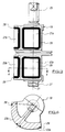
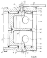
- the apparatus 1 shown schematically in Figures 1A, 1B, 2A and 2B is a 3-way diverter valve for controlling the liquid flow in a duplex strainer.
- Two chambers 3 and 5 are connected in parallel, having fluid inlets 7a and 7b and fluid outlets 9a and 9b respectively, and each containing a filter element 11a and 11b respectively, to a central chamber 13.
- Fluid enters the apparatus 1 through an inlet port 15 and exits the apparatus through an outlet port 17 having passed through one or both of the filter elements 11a and 11b, as described below.
- the flow of the fluid through the apparatus 1 is indicated by the arrows, the broken arrows indicating the flow of filtered fluid.
- the central chamber 13 contains a pivotable member 19 to which are mounted inlet and outlet seals 21 and 23 respectively. Rotation of the member 19 about its central axis 31 moves the seals 21,23 into or out of sealing engagement with the inlet and outlet 7a, 9a, 7b, 9b of each of the chambers 3,5 substantially simultaneously.
- Figures 2A and 2B illustrate the member 19 in a second sealing position in which fluid is constrained to flow through chamber 5 and filter 11b.
- chamber 5 With member 19 in the first sealing position, chamber 5 is sealed off from the flow of fluid, enabling the filter 11b to be removed for cleaning or replacement, and chamber 3 is sealed off from the fluid flow when the member 19 is in the second sealing position.
- the inlet and outlet 7a,9a,7b,9b to each chamber 3,5 is at least partially open for fluid to flow therethrough, thereby ensuring that there is no interruption to the fluid flow through the apparatus at any time.
- the member 19 shown in Figures 3 and 4 is mounted so as to pivot about two plug axles 25,27 about a pivot axis 31 within a cylindrical central chamber (see Figure 5).
- the inlet and outlet seals 21,23 comprise cylindrical sealing faces 21a,21b,23a,23b, the radii of which are the same as the radius of the central chamber 13.
- the pivot axis 31 is parallel to but spaced from the longitudinal axis 33 of the central chamber 13 (i.e. the member 19 is mounted eccentrically in the chamber 13), and the longitudinal axes of each of the sealing faces are parallel to but spaced from the pivot axis 31 (i.e. the sealing faces are eccentric with respect to the member 19).
- the arrangement is such that, with the member 19 in the first sealing position (shown in Figure 1A) the longitudinal axes of sealing faces 21a and 23a are coaxial with the axis 33 of the central chamber 13, and the inlet 7a and outlet 9a to chamber 3 are effectively sealed by sealing faces 21a and 23a.
- sealing faces 21a,21b,23a,23b are shown as being integral to the member 19; the sealing faces could equally be manufactured as separate components which may be releasably mounted to the member, by bolts, for example (not shown). Such separate sealing faces could be more easily manufactured.
- each seal face moves through an arcuate path towards the respective inlet or outlet with a gradually reducing clearance therebetween, until the seal faces mate against the wall of the central chamber 12, simultaneously sealing off the inlet and outlet to one or other chamber 3,5.
- a sealing face and the respective inlet or outlet there is a small degree of relative sliding movement therebetween, which sliding acts to wipe clean any debris from the mating surfaces to provide a good seal.
- a further advantage of the eccentric seal faces is that when the member is rotated away from a sealing position there is an increasing clearance within the wall of the chamber 13, thereby avoiding any interruption to the flow.
- each sealing face is provided with an 'O' seal 29 such as a soft seal or a bonded seal, seated in a slot with a reverse taper, so as to improve the seal between a sealing face and the respective inlet or outlet.
- the sliding movement between the 'O' seals 29 and the wall of the central chamber around the inlet or outlet acts to remove any debris and continued motion ensures correct energising of the 'O' seal 29, thereby ensuring a good seal.
- the 'O' seals 29 could be located in slots in the wall of the central chamber 13 surrounding each inlet and outlet.
- the method of energizing the 'O' seals 29 around each inlet or outlet provides a positive locking feature.
- the fluid flow is under pressure, once there is a sufficient pressure difference between the central chamber 13 and whichever chamber 3 or 5 has been sealed, as, for example, when that chamber is opened to gain access to the filter 11 it is then impossible to pivot the member 19, or to actuate the valve, until the pressure differential is removed, by repressurising the sealed chamber.
- Means are provided to repressurise both chambers as and when necessary; if the fluid is a liquid, this may conveniently comprise a pipe with a valve connecting the two chambers 3 and 5, and air vents (not shown) may be provided in each chamber.
- fluid is a gas
- further means may be provided to purge each chamber 3,5 of air which might contaminate the gas.
- the central chamber 13 may be easily manufactured as a machined cylindrical body 35 (see Figure 5) with a top cover 37 and a bottom cover 39 attached thereto by bolts 41.
- the seal between the covers 37,39 and the body is provided by further 'O' ring seals 43.
- the member 19 pivots about stub axles 25, 27 which seat bearing recesses 57,59 formed in the top and bottom covers 37,39 and are sealed by further 'O' ring seals 49.
- the outer ends of the stub axles 25,27 are open to atmospheric pressure, and the are of equal diameter. With such an arrangement, the pivot member 19 is effectively hydraulically balanced along its longitudinal axis 31 so that expensive thrust bearings are not required. If there is an appreciable pressure differential between the fluid entering through inlet port 15 and fluid exiting through outlet port 17, the stub axles could be made of different diameters so as to retain the hydraulic balancing effect.
- a handle 55 may be fixed by a shaft 51 and locking pin 53 to one of the stub axles 25 so that the valve may be operated manually, or means (not shown) may be provided so as to operate the valve automatically. However the valve is operated, the sealing or opening of the fluid path through each of the chambers 3,5 is effected simultaneously.
- the member 19 is formed with a circular division seal plate 47 which is coaxial with a portion of the cylindrical central chamber 13, so as to ensure that fluid flows through either or both the chambers 3,5 but not directly between the inlet and outlet parts 15,19.
- An 'O' ring seal 45 may be provided to improve the seal between the division plate 47 and the central chamber 13.
Landscapes
- Engineering & Computer Science (AREA)
- General Engineering & Computer Science (AREA)
- Mechanical Engineering (AREA)
- Multiple-Way Valves (AREA)
- Gas Separation By Absorption (AREA)
- Telephone Function (AREA)
Claims (11)
- Appareil pour dériver l'écoulement d'un fluide depuis un chemin vers un autre chemin, les deux chemins étant définis dans un logement qui a un axe longitudinal, englobant un élément de soupape (19) ayant plusieurs faces d'obturation (21, 23) et étant monté de façon rotative dans le logement, chaque face étant adaptée pour former une obturation contre l'admission (7) ou la sortie (9) de l'un des chemins, l'élément (19) pouvant être déplacé entre une première position en laquelle tant l'admission (7b) que la sortie (9b) du deuxième chemin sont ouvertes pour que le fluide s'écoule à travers elles, et tant l'admission (7a) que la sortie (9a) du premier chemin sont obturées, et une deuxième position en laquelle tant l'admission (7a) que la sortie (9a) du premier chemin sont ouvertes pour que le fluide s'écoule à travers elles, et tant l'admission (7b) que la sortie (9b) du deuxième chemin sont obturées, le mouvement de l'élément (19) effectuant sensiblement simultanément l'obturation ou l'ouverture de l'admission et de la sortie de chaque chemin d'écoulement, et les deux chemins étant au moins partiellement ouverts pour l'écoulement du fluide à travers ceux-ci lorsque l'élément (19) est entre la première et la deuxième positions, caractérisé en ce que l'élément de soupape (19) est monté de façon pivotante avec son axe de pivot parallèle à l'axe longitudinal du logement mais ne coïncidant pas avec celui-ci, et en ce que chaque face d'obturation (21, 23) sur l'élément de soupape (19) délimite une section d'une surface cylindrique, les faces d'obturation cylindriques étant excentriques relativement à l'axe de pivot (31) de l'élément de soupape.
- Appareil selon la Revendication 1, dans lequel l'admission et la sortie (7, 9) de chaque chemin englobent un orifice formé dans une paroi du logement, chaque surface d'obturation (21, 23) sur l'élément rotatif (19) ayant un rayon sensiblement égal au rayon du logement.
- Appareil selon la Revendication 1 ou la Revendication 2, dans lequel les axes longitudinaux des faces d'obturation cylindriques (21, 23) pour l'obturation de l'admission et de la sortie (7, 9) de chaque chemin sont coaxiaux.
- Appareil selon l'une quelonque des Revendications précédentes, dans lequel le logement est cylindrique et a un rayon interne sensiblement constant.
- Appareil selon l'une quelconque des Revendications précédentes, dans lequel une rainure est prévue pour monter un joint étanche mou (29) soit autour de la périphérie de chaque face d'obturation (21, 23), soit autour de chaque admission et sortie de chemin de fluide, pour améliorer l'étanchéité entre elles.
- Appareil selon l'une quelconque des Revendications précédentes, dans lequel l'élément de soupape (19) est monté dans un logement cylindrique sur des faux arbres coaxiaux (25, 27) de diamètre égal, les extrémités des faux arbres se prolongeant à travers le logement.
- Appareil selon l'une quelconque des Revendications précédentes, englobant des moyens de détente de la pression du fluide dans chaque chemin lorsque l'admission (7) et la sortie (9) du chemin sont obturées, et des moyens pour vider le fluide hors de ce chemin et pour rendre possible l'accès au chemin.
- Appareil selon l'une quelconque des Revendications précédentes, englobant des moyens de filtration (11a, 11b) dans l'un des chemins ou dans les deux.
- Appareil selon l'une quelconque des Revendications précédentes, dans lequel les faces d'obturation (21, 23) font partie intégrante de l'élément de soupape (19).
- Appareil selon l'une quelconque des Revendications précédentes, dans lequel les faces d'obturation (21,23) sont agencées en paires espacées circonférentiellement, chaque paire de faces d'obturation étant adaptée pour former une étanchéité contre les admissions (7) ou les sorties (9) des premier et deuxièmes chemins.
- Appareil selon la Revendication 10, dans lequel les paires de faces d'obturation sont espacées longitudinalement le long de l'axe de pivot de l'élément de soupape (19).
Applications Claiming Priority (2)
| Application Number | Priority Date | Filing Date | Title |
|---|---|---|---|
| GB9310397A GB2278182B (en) | 1993-05-20 | 1993-05-20 | Improvements in and relating to diverting fluid flow |
| GB9310397 | 1993-05-20 |
Publications (2)
| Publication Number | Publication Date |
|---|---|
| EP0631073A1 EP0631073A1 (fr) | 1994-12-28 |
| EP0631073B1 true EP0631073B1 (fr) | 2000-12-13 |
Family
ID=10735816
Family Applications (1)
| Application Number | Title | Priority Date | Filing Date |
|---|---|---|---|
| EP94303511A Expired - Lifetime EP0631073B1 (fr) | 1993-05-20 | 1994-05-17 | Améliorations dans et en relation avec dérivation de flux d'un fluide |
Country Status (7)
| Country | Link |
|---|---|
| US (1) | US5423349A (fr) |
| EP (1) | EP0631073B1 (fr) |
| AT (1) | ATE198100T1 (fr) |
| AU (1) | AU681638B2 (fr) |
| DE (1) | DE69426401D1 (fr) |
| GB (1) | GB2278182B (fr) |
| SG (1) | SG48861A1 (fr) |
Families Citing this family (11)
| Publication number | Priority date | Publication date | Assignee | Title |
|---|---|---|---|---|
| US5816290A (en) * | 1996-03-13 | 1998-10-06 | Fleck Controls, Inc. | Rotary control valve for a water conditioning system |
| AUPO412896A0 (en) * | 1996-12-11 | 1997-01-09 | Upham, John D. | Electromagnetic gas injection valve |
| US20060270974A1 (en) * | 2005-05-16 | 2006-11-30 | Kerberos Proximal Solutions, Inc. | Methods and systems for filtering aspirated materials |
| US20070039653A1 (en) * | 2005-08-16 | 2007-02-22 | Maggard James J | Switching valve |
| RU2342582C2 (ru) * | 2006-09-27 | 2008-12-27 | Открытое акционерное общество "Ракетно-космическая корпорация "Энергия" имени С.П. Королева" | Устройство деления потока жидкости |
| DE102009049993A1 (de) | 2009-10-20 | 2011-04-21 | Continental Automotive Gmbh | Turbine für einen Abgasturbolader, Abgasturbolader, Kraftfahrzeug und Verfahren zum Betreiben eines Abgasturboladers |
| CN106224595B (zh) * | 2016-10-10 | 2019-06-18 | 国家海洋局天津海水淡化与综合利用研究所 | 一体化六通阀 |
| US11346453B2 (en) | 2019-03-03 | 2022-05-31 | California Controlled Atmosphere | Switching assembly for pressure relief valves |
| US12044320B2 (en) | 2019-03-03 | 2024-07-23 | California Controlled Atmosphere | Switching assembly for pressure relief valves |
| RU2771472C1 (ru) * | 2021-06-29 | 2022-05-04 | Публичное акционерное общество "Ракетно-космическая корпорация "Энергия" имени С.П. Королёва" | Устройство деления потока жидкости |
| CN118529810B (zh) * | 2024-07-24 | 2024-11-19 | 上海晨菲水务科技有限公司 | 一种智慧型管网叠压供水一体化机 |
Family Cites Families (7)
| Publication number | Priority date | Publication date | Assignee | Title |
|---|---|---|---|---|
| FR1293654A (fr) * | 1961-04-07 | 1962-05-18 | Snecma | Dispositif de distribution de fluide applicable notamment à la gouverne par jet desavions à décollage vertical |
| US3595270A (en) * | 1970-01-20 | 1971-07-27 | Andale Co | Plug valve construction and operating mechanism |
| FR2151469A5 (fr) * | 1971-08-30 | 1973-04-20 | Pont A Mousson Fond | |
| IT1044523B (it) * | 1975-07-18 | 1980-03-31 | Gilardini Spa | Valvola deviatrice a sei vie per liquidi |
| DE2710844C2 (de) * | 1977-03-12 | 1983-03-24 | Boll & Kirch Filterbau GmbH, 5014 Kerpen | Absperrventil |
| DE3300217A1 (de) * | 1982-01-07 | 1983-08-11 | A P V International Ltd., Crawley, Sussex | Stroemungssteuerungsventil |
| US5211195A (en) * | 1992-06-12 | 1993-05-18 | Teledyne Industries, Inc. | Fluid valve systems |
-
1993
- 1993-05-20 GB GB9310397A patent/GB2278182B/en not_active Expired - Fee Related
-
1994
- 1994-05-17 SG SG1996003148A patent/SG48861A1/en unknown
- 1994-05-17 EP EP94303511A patent/EP0631073B1/fr not_active Expired - Lifetime
- 1994-05-17 DE DE69426401T patent/DE69426401D1/de not_active Expired - Lifetime
- 1994-05-17 AT AT94303511T patent/ATE198100T1/de not_active IP Right Cessation
- 1994-05-19 US US08/245,871 patent/US5423349A/en not_active Expired - Fee Related
- 1994-05-20 AU AU63210/94A patent/AU681638B2/en not_active Ceased
Also Published As
| Publication number | Publication date |
|---|---|
| US5423349A (en) | 1995-06-13 |
| EP0631073A1 (fr) | 1994-12-28 |
| GB2278182A (en) | 1994-11-23 |
| GB2278182B (en) | 1997-05-28 |
| GB9310397D0 (en) | 1993-07-07 |
| AU681638B2 (en) | 1997-09-04 |
| AU6321094A (en) | 1994-11-24 |
| SG48861A1 (en) | 1998-05-18 |
| DE69426401D1 (de) | 2001-01-18 |
| ATE198100T1 (de) | 2000-12-15 |
Similar Documents
| Publication | Publication Date | Title |
|---|---|---|
| US3618781A (en) | Duplex filtering device | |
| US5199458A (en) | Multi-way valve | |
| US5607582A (en) | Filter system for liquids | |
| US5423349A (en) | Diverting fluid flow | |
| US3640310A (en) | Multiport valve | |
| EP1861189B1 (fr) | Filtre de purification d'eau facilement remplaçable au moyen d'un raccord | |
| US20130299014A1 (en) | Fluid diverting system | |
| EP1337773B1 (fr) | Soupape a quatre voies | |
| US5462251A (en) | Method and apparatus for controlling the flow of fluids | |
| CA2139975C (fr) | Crepine double | |
| US20010011557A1 (en) | Backwash valve | |
| FI68714C (fi) | Tryckutjaemnings-trevaegs-oeverfoeringsventil | |
| AU2001282863A1 (en) | Four way valve | |
| US4786409A (en) | Duplex filter assembly | |
| US10926205B2 (en) | Cast filter assembly-modular design | |
| KR100498668B1 (ko) | 정수기의 원수 차단 장치 | |
| US4501295A (en) | Transfer valve | |
| US4653536A (en) | Fluid flow reverser assembly | |
| US20250083076A1 (en) | Bag filter housing large-bore valve duplex filter with hydraulic lift assist | |
| JP3586007B2 (ja) | 切換コック | |
| JPH0494705A (ja) | 濾過装置 | |
| JP2002243052A (ja) | 五方切換弁および濾過装置 | |
| JPS63264187A (ja) | 流体処理用カ−トリツジ | |
| JPH11270720A (ja) | 多方弁および浄水器 | |
| JP2520948Y2 (ja) | 弁内蔵型濾過器 |
Legal Events
| Date | Code | Title | Description |
|---|---|---|---|
| PUAI | Public reference made under article 153(3) epc to a published international application that has entered the european phase |
Free format text: ORIGINAL CODE: 0009012 |
|
| AK | Designated contracting states |
Kind code of ref document: A1 Designated state(s): AT BE CH DE DK ES FR GR IE IT LI LU MC NL PT SE |
|
| 17P | Request for examination filed |
Effective date: 19950628 |
|
| 17Q | First examination report despatched |
Effective date: 19961213 |
|
| RBV | Designated contracting states (corrected) |
Designated state(s): AT BE CH DE DK ES FR GR IE IT LI LU MC NL PT SE |
|
| GRAG | Despatch of communication of intention to grant |
Free format text: ORIGINAL CODE: EPIDOS AGRA |
|
| GRAG | Despatch of communication of intention to grant |
Free format text: ORIGINAL CODE: EPIDOS AGRA |
|
| GRAG | Despatch of communication of intention to grant |
Free format text: ORIGINAL CODE: EPIDOS AGRA |
|
| GRAH | Despatch of communication of intention to grant a patent |
Free format text: ORIGINAL CODE: EPIDOS IGRA |
|
| GRAH | Despatch of communication of intention to grant a patent |
Free format text: ORIGINAL CODE: EPIDOS IGRA |
|
| GRAA | (expected) grant |
Free format text: ORIGINAL CODE: 0009210 |
|
| AK | Designated contracting states |
Kind code of ref document: B1 Designated state(s): AT BE CH DE DK ES FR GR IE IT LI LU MC NL PT SE |
|
| PG25 | Lapsed in a contracting state [announced via postgrant information from national office to epo] |
Ref country code: SE Free format text: THE PATENT HAS BEEN ANNULLED BY A DECISION OF A NATIONAL AUTHORITY Effective date: 20001213 Ref country code: NL Free format text: LAPSE BECAUSE OF FAILURE TO SUBMIT A TRANSLATION OF THE DESCRIPTION OR TO PAY THE FEE WITHIN THE PRESCRIBED TIME-LIMIT Effective date: 20001213 Ref country code: LI Free format text: LAPSE BECAUSE OF FAILURE TO SUBMIT A TRANSLATION OF THE DESCRIPTION OR TO PAY THE FEE WITHIN THE PRESCRIBED TIME-LIMIT Effective date: 20001213 Ref country code: IT Free format text: LAPSE BECAUSE OF FAILURE TO SUBMIT A TRANSLATION OF THE DESCRIPTION OR TO PAY THE FEE WITHIN THE PRE;WARNING: LAPSES OF ITALIAN PATENTS WITH EFFECTIVE DATE BEFORE 2007 MAY HAVE OCCURRED AT ANY TIME BEFORE 2007. THE CORRECT EFFECTIVE DATE MAY BE DIFFERENT FROM THE ONE RECORDED.SCRIBED TIME-LIMIT Effective date: 20001213 Ref country code: GR Free format text: LAPSE BECAUSE OF NON-PAYMENT OF DUE FEES Effective date: 20001213 Ref country code: FR Free format text: LAPSE BECAUSE OF FAILURE TO SUBMIT A TRANSLATION OF THE DESCRIPTION OR TO PAY THE FEE WITHIN THE PRESCRIBED TIME-LIMIT Effective date: 20001213 Ref country code: ES Free format text: THE PATENT HAS BEEN ANNULLED BY A DECISION OF A NATIONAL AUTHORITY Effective date: 20001213 Ref country code: CH Free format text: LAPSE BECAUSE OF FAILURE TO SUBMIT A TRANSLATION OF THE DESCRIPTION OR TO PAY THE FEE WITHIN THE PRESCRIBED TIME-LIMIT Effective date: 20001213 Ref country code: BE Free format text: LAPSE BECAUSE OF FAILURE TO SUBMIT A TRANSLATION OF THE DESCRIPTION OR TO PAY THE FEE WITHIN THE PRESCRIBED TIME-LIMIT Effective date: 20001213 Ref country code: AT Free format text: LAPSE BECAUSE OF FAILURE TO SUBMIT A TRANSLATION OF THE DESCRIPTION OR TO PAY THE FEE WITHIN THE PRESCRIBED TIME-LIMIT Effective date: 20001213 |
|
| REF | Corresponds to: |
Ref document number: 198100 Country of ref document: AT Date of ref document: 20001215 Kind code of ref document: T |
|
| REG | Reference to a national code |
Ref country code: CH Ref legal event code: EP |
|
| REF | Corresponds to: |
Ref document number: 69426401 Country of ref document: DE Date of ref document: 20010118 |
|
| REG | Reference to a national code |
Ref country code: IE Ref legal event code: FG4D |
|
| PG25 | Lapsed in a contracting state [announced via postgrant information from national office to epo] |
Ref country code: PT Free format text: LAPSE BECAUSE OF FAILURE TO SUBMIT A TRANSLATION OF THE DESCRIPTION OR TO PAY THE FEE WITHIN THE PRESCRIBED TIME-LIMIT Effective date: 20010313 Ref country code: DK Free format text: LAPSE BECAUSE OF FAILURE TO SUBMIT A TRANSLATION OF THE DESCRIPTION OR TO PAY THE FEE WITHIN THE PRESCRIBED TIME-LIMIT Effective date: 20010313 |
|
| PG25 | Lapsed in a contracting state [announced via postgrant information from national office to epo] |
Ref country code: DE Free format text: LAPSE BECAUSE OF FAILURE TO SUBMIT A TRANSLATION OF THE DESCRIPTION OR TO PAY THE FEE WITHIN THE PRESCRIBED TIME-LIMIT Effective date: 20010314 |
|
| NLV1 | Nl: lapsed or annulled due to failure to fulfill the requirements of art. 29p and 29m of the patents act | ||
| EN | Fr: translation not filed | ||
| PG25 | Lapsed in a contracting state [announced via postgrant information from national office to epo] |
Ref country code: LU Free format text: LAPSE BECAUSE OF NON-PAYMENT OF DUE FEES Effective date: 20010517 Ref country code: IE Free format text: LAPSE BECAUSE OF NON-PAYMENT OF DUE FEES Effective date: 20010517 |
|
| PG25 | Lapsed in a contracting state [announced via postgrant information from national office to epo] |
Ref country code: MC Free format text: LAPSE BECAUSE OF NON-PAYMENT OF DUE FEES Effective date: 20010531 |
|
| REG | Reference to a national code |
Ref country code: CH Ref legal event code: PL |
|
| PLBE | No opposition filed within time limit |
Free format text: ORIGINAL CODE: 0009261 |
|
| STAA | Information on the status of an ep patent application or granted ep patent |
Free format text: STATUS: NO OPPOSITION FILED WITHIN TIME LIMIT |
|
| 26N | No opposition filed | ||
| REG | Reference to a national code |
Ref country code: IE Ref legal event code: MM4A |