EP0631111A1 - Verfahren und Vorrichtung zum Bestimmen der Position eines Flugkörpers - Google Patents
Verfahren und Vorrichtung zum Bestimmen der Position eines Flugkörpers Download PDFInfo
- Publication number
- EP0631111A1 EP0631111A1 EP94401318A EP94401318A EP0631111A1 EP 0631111 A1 EP0631111 A1 EP 0631111A1 EP 94401318 A EP94401318 A EP 94401318A EP 94401318 A EP94401318 A EP 94401318A EP 0631111 A1 EP0631111 A1 EP 0631111A1
- Authority
- EP
- European Patent Office
- Prior art keywords
- point
- aircraft
- image
- coordinates
- remarkable
- Prior art date
- Legal status (The legal status is an assumption and is not a legal conclusion. Google has not performed a legal analysis and makes no representation as to the accuracy of the status listed.)
- Granted
Links
- 238000000034 method Methods 0.000 title claims abstract description 31
- 239000013598 vector Substances 0.000 claims abstract description 47
- 238000005259 measurement Methods 0.000 claims abstract description 9
- 230000033001 locomotion Effects 0.000 claims description 12
- 239000011159 matrix material Substances 0.000 claims description 5
- 230000005540 biological transmission Effects 0.000 claims description 2
- 230000014509 gene expression Effects 0.000 claims description 2
- 238000012550 audit Methods 0.000 description 3
- 230000010354 integration Effects 0.000 description 3
- 230000005855 radiation Effects 0.000 description 3
- 230000001133 acceleration Effects 0.000 description 2
- 238000001514 detection method Methods 0.000 description 1
- 238000006073 displacement reaction Methods 0.000 description 1
- 230000010365 information processing Effects 0.000 description 1
Images

Classifications
-
- F—MECHANICAL ENGINEERING; LIGHTING; HEATING; WEAPONS; BLASTING
- F41—WEAPONS
- F41G—WEAPON SIGHTS; AIMING
- F41G7/00—Direction control systems for self-propelled missiles
- F41G7/34—Direction control systems for self-propelled missiles based on predetermined target position data
- F41G7/343—Direction control systems for self-propelled missiles based on predetermined target position data comparing observed and stored data of target position or of distinctive marks along the path towards the target
-
- G—PHYSICS
- G01—MEASURING; TESTING
- G01C—MEASURING DISTANCES, LEVELS OR BEARINGS; SURVEYING; NAVIGATION; GYROSCOPIC INSTRUMENTS; PHOTOGRAMMETRY OR VIDEOGRAMMETRY
- G01C21/00—Navigation; Navigational instruments not provided for in groups G01C1/00 - G01C19/00
- G01C21/005—Navigation; Navigational instruments not provided for in groups G01C1/00 - G01C19/00 with correlation of navigation data from several sources, e.g. map or contour matching
-
- G—PHYSICS
- G01—MEASURING; TESTING
- G01S—RADIO DIRECTION-FINDING; RADIO NAVIGATION; DETERMINING DISTANCE OR VELOCITY BY USE OF RADIO WAVES; LOCATING OR PRESENCE-DETECTING BY USE OF THE REFLECTION OR RERADIATION OF RADIO WAVES; ANALOGOUS ARRANGEMENTS USING OTHER WAVES
- G01S11/00—Systems for determining distance or velocity not using reflection or reradiation
- G01S11/12—Systems for determining distance or velocity not using reflection or reradiation using electromagnetic waves other than radio waves
Definitions
- the present invention relates to a method and a device for determining the position of an aircraft.
- the invention can be implemented only to determine the position of said aircraft, or even to ensure the navigation of said aircraft and / or the guiding of the latter towards a target, by using information relating to said position.
- the present invention is particularly suitable for missiles, and in particular for surveillance missiles, reconnaissance drones and missiles intended to destroy targets at great distance.
- the known positioning or navigation devices for aircraft comprise at least one inertial unit implementing high precision gyrometers and accelerometers, as soon as the flight time is long.
- the known positioning or navigation devices for aircraft comprise at least one inertial unit implementing high precision gyrometers and accelerometers, as soon as the flight time is long.
- the known positioning or navigation devices are expensive.
- the object of the present invention is to determine the position, speed and attitude of an aircraft, in order to allow navigation and / or guidance of said aircraft without the use of an expensive inertial unit.
- a camera sensitive to infrared or visible radiation comprising in its focal plane (image plane) a matrix of photodetectors (for example CCD sensors), which makes it possible to '' obtain a representation of the landscape, compatible with an information processing system.
- a matrix of photodetectors for example CCD sensors
- Such cameras are widely used in navigation devices. and guidance of reconnaissance missiles and they make it possible to obtain video images of the landscape at frequencies of the order of 25 Hz. Thanks to such a camera, it is therefore possible to measure, on said matrix of photodetectors, the coordinates of the image of said remarkable point M of the landscape, for example a "hot" point thereof.
- the vector therefore represents the variations in attitude of the aircraft around the roll, pitch and yaw axes thereof. To measure it, it suffices to mount three gyros on board said aircraft, each of said gyros being associated with one of said axes.
- the integration of the equation of motion can be carried out at the rate of the measurements of the components p , q and r of the vector by gyrometers. This integration can be done by the implementation of a known method, such as that of RUNGE KUTTA.
- a portion of the image surrounding the image m of said remarkable point M is stored in memory and one performs a correlation with an image portion around the estimated position m * by searching for the position which gives the maximum correlation and which therefore defines the true position of the image of point M in said image plane.
- the position of the image portion surrounding point M at time ti-1 can be estimated on several points, which makes it possible to refine the correlation by taking into account the rotation of the image and its magnification during displacement of the aircraft between times ti-1 and ti .
- the coordinates of the image mi of said fictitious point Mi are thus obtained, at time ti , in the image plane of the camera.
- the point of intersection fi at time ti , must be on the vector image , in the image plane. Therefore, to determine the coordinates from said point of intersection, two different methods can be used.
- At least two image vectors are determined , corresponding to two different remarkable points M, and the coordinates of said point of intersection fi are determined as those of the intersection of said two image vectors .
- an estimated position f * of this point of intersection is determined. at the instant ti using the same technique as for the point mi by replacing in the differential equation y by v / u and z by w / u. This estimate does not take into account the variations of u , v and w during the integration time. We then project the point f * thus determined on the line mmi to obtain the point of intersection fi at the instant ti .
- the component u of the average speed, perpendicular to the image plane can be estimated from external parameters, for example from the engine speed of the aircraft and atmospheric conditions, or from a given acceleration measurement by an accelerometer mounted in the axis of the aircraft.
- the present invention also relates to a device for implementing the above method.
- said calculation means are, in their entirety, on board said aircraft.
- a transmission link can be provided between said aircraft and a ground control station and said calculation means can be, at least partially, arranged in said control station.
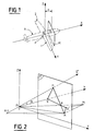
- FIG. 1 shows, schematically, an aircraft provided with a camera image plane and associated with a reference system used in the method according to the invention.
- Figure 2 illustrates the principle of determining the distance from a remarkable point on the landscape.
- FIG. 3 shows points necessary for the implementation of the method according to the invention and located in an image plane.
- FIG. 4 schematically illustrates a device for implementing the method according to the invention.
- the method according to the invention makes it possible to determine the successive positions of an aircraft A in motion, at each instant of a plurality of successive instants spaced from each other by a duration ⁇ t.
- an aircraft frame of reference linked to said aircraft A of axes OX, OY and OZ is defined, in which the axis OX corresponds to the axis of the aircraft, the axis OY corresponds to the axis of the wings 1 and 2 of said aircraft A and the axis OZ is perpendicular to these latter axes OX and OY, as shown in FIG. 1.
- a camera (not shown in FIG.
- image plane PI perpendicular to the axis OX and it intersects this axis OX at a point 01, located at a distance ⁇ from the point O.
- segment PiQ represents the distance X separating the position Pi from the plane ⁇ .
- the calculation is carried out, not from the preceding plane ⁇ , but from the image plane PI parallel to the plane ⁇ and intersecting the axis OX at point O1.
- the points Q, Fi, R, M and H above have respectively for image, in the plane PI, points O1, fi , mi , m and h , as shown in Figure 3.
- the point mi is both the image of point R and that of point Mi.
- a frame of reference (O1y, O1z) is defined in the image plane PI such that O1y and O1z are respectively parallel to OY and OZ.
- the coordinate u of the speed vector along the axis OX is determined by external means, as will be seen below, while the coordinates v , w of this speed vector are determined from the coordinates of the point of intersection fi in the image plane (O1y, O1z), this point having as coordinates v / u and w / u.
- the position and the speed of said aircraft are known at a given instant ti .
- a device 3 comprising calculation means 4, as shown in FIG. 4.
- These calculation means 4 receive, via a link 5, the measurements of the coordinates of the image m of one or more remarkable points M determined by the use of a camera 6, directed according to a fixed orientation with respect to the aircraft, towards the front.
- Said device 3 further comprises gyrometers 7, 8 and 9 connected respectively by links 10, 11 and 12 to said calculation means 4 and transmitting to the latter the components of the instantaneous rotation vector of the aircraft along the axes of roll, pitch and yaw.
- said device 3 comprises means 13 for estimating the axial speed of said aircraft, which are connected to the calculation means 4 by a link 14.
- This speed can, for example, be determined by an acceleration measurement given by an accelerometer . It can also be determined by the propulsion regime of the aircraft and atmospheric conditions.
- said calculation means 4 determine, in a frame of reference linked to said aircraft, the coordinates of the remarkable points M of the landscape in which we are interested, as well as the components of the speed vector of the aircraft.
- Said calculation means 4 transmit these results via a link 15.
- calculation means 4 can be on board the aircraft or can be, at least partially, placed in a control station installed on the ground.
Landscapes
- Engineering & Computer Science (AREA)
- Radar, Positioning & Navigation (AREA)
- Remote Sensing (AREA)
- Physics & Mathematics (AREA)
- General Physics & Mathematics (AREA)
- Electromagnetism (AREA)
- Automation & Control Theory (AREA)
- Chemical & Material Sciences (AREA)
- Combustion & Propulsion (AREA)
- General Engineering & Computer Science (AREA)
- Navigation (AREA)
- Image Analysis (AREA)
Applications Claiming Priority (2)
| Application Number | Priority Date | Filing Date | Title |
|---|---|---|---|
| FR9307543A FR2707001B1 (de) | 1993-06-22 | 1993-06-22 | |
| FR9307543 | 1993-06-22 |
Publications (2)
| Publication Number | Publication Date |
|---|---|
| EP0631111A1 true EP0631111A1 (de) | 1994-12-28 |
| EP0631111B1 EP0631111B1 (de) | 1997-08-06 |
Family
ID=9448406
Family Applications (1)
| Application Number | Title | Priority Date | Filing Date |
|---|---|---|---|
| EP19940401318 Expired - Lifetime EP0631111B1 (de) | 1993-06-22 | 1994-06-13 | Verfahren und Vorrichtung zum Bestimmen der Position eines Flugkörpers |
Country Status (5)
| Country | Link |
|---|---|
| EP (1) | EP0631111B1 (de) |
| DE (1) | DE69404769T2 (de) |
| ES (1) | ES2106467T3 (de) |
| FR (1) | FR2707001B1 (de) |
| GR (1) | GR3024723T3 (de) |
Cited By (1)
| Publication number | Priority date | Publication date | Assignee | Title |
|---|---|---|---|---|
| CN101532841B (zh) * | 2008-12-30 | 2010-09-08 | 华中科技大学 | 基于地标捕获跟踪的飞行器导航定位方法 |
Families Citing this family (1)
| Publication number | Priority date | Publication date | Assignee | Title |
|---|---|---|---|---|
| DE102007054950B4 (de) * | 2007-11-17 | 2013-05-02 | Mbda Deutschland Gmbh | Verfahren zur Stützung der selbsttätigen Navigation eines niedrig fliegenden Flugkörpers |
Citations (4)
| Publication number | Priority date | Publication date | Assignee | Title |
|---|---|---|---|---|
| DE3446009A1 (de) * | 1984-12-17 | 1986-06-26 | Messerschmitt-Bölkow-Blohm GmbH, 8012 Ottobrunn | Vorrichtung und verfahren zur bestimmung der roll-, nick- und gierbewegung sowie der flugrichtung eines flugkoerpers |
| US4695959A (en) * | 1984-04-06 | 1987-09-22 | Honeywell Inc. | Passive range measurement apparatus and method |
| FR2642529A1 (fr) * | 1987-11-17 | 1990-08-03 | Gen Electric Co Plc | Procede et dispositif de mesure de la position d'un vehicule |
| EP0436213A2 (de) * | 1990-01-02 | 1991-07-10 | Honeywell Inc. | System zur Detektion eines Hindernisses |
-
1993
- 1993-06-22 FR FR9307543A patent/FR2707001B1/fr not_active Expired - Fee Related
-
1994
- 1994-06-13 EP EP19940401318 patent/EP0631111B1/de not_active Expired - Lifetime
- 1994-06-13 ES ES94401318T patent/ES2106467T3/es not_active Expired - Lifetime
- 1994-06-13 DE DE1994604769 patent/DE69404769T2/de not_active Expired - Fee Related
-
1997
- 1997-09-16 GR GR970402366T patent/GR3024723T3/el unknown
Patent Citations (4)
| Publication number | Priority date | Publication date | Assignee | Title |
|---|---|---|---|---|
| US4695959A (en) * | 1984-04-06 | 1987-09-22 | Honeywell Inc. | Passive range measurement apparatus and method |
| DE3446009A1 (de) * | 1984-12-17 | 1986-06-26 | Messerschmitt-Bölkow-Blohm GmbH, 8012 Ottobrunn | Vorrichtung und verfahren zur bestimmung der roll-, nick- und gierbewegung sowie der flugrichtung eines flugkoerpers |
| FR2642529A1 (fr) * | 1987-11-17 | 1990-08-03 | Gen Electric Co Plc | Procede et dispositif de mesure de la position d'un vehicule |
| EP0436213A2 (de) * | 1990-01-02 | 1991-07-10 | Honeywell Inc. | System zur Detektion eines Hindernisses |
Cited By (1)
| Publication number | Priority date | Publication date | Assignee | Title |
|---|---|---|---|---|
| CN101532841B (zh) * | 2008-12-30 | 2010-09-08 | 华中科技大学 | 基于地标捕获跟踪的飞行器导航定位方法 |
Also Published As
| Publication number | Publication date |
|---|---|
| EP0631111B1 (de) | 1997-08-06 |
| DE69404769T2 (de) | 1997-12-18 |
| FR2707001B1 (de) | 1995-12-22 |
| DE69404769D1 (de) | 1997-09-11 |
| FR2707001A1 (de) | 1994-12-30 |
| ES2106467T3 (es) | 1997-11-01 |
| GR3024723T3 (en) | 1997-12-31 |
Similar Documents
| Publication | Publication Date | Title |
|---|---|---|
| EP0148704B1 (de) | Überwachungssystem mittels eines gelenkten Flugkörpers zur Lokalisierung eines Zieles | |
| EP2932182B1 (de) | Verfahren zur genauen geolokalisierung eines bildsensors an bord eines flugzeugs | |
| EP3058431B1 (de) | Verfahren und vorrichtung zur geländeidentifikation während des fluges einer mikrodrohne | |
| EP2361368B1 (de) | Verfahren zum bestimmen eines kurses in der richtung des geografischen nordpols unter verwendung einer trägheitsmesseinheit | |
| FR2638544A1 (fr) | Systeme pour determiner la position spatiale d'un objet en mouvement, applique notamment a l'atterrissage des avions | |
| EP2188590B1 (de) | Verfahren und Vorrichtung zur Abstandsmessung gestützt auf ein stabilisiertes Bild | |
| EP2495531B1 (de) | Verfahren zum Messen der Stabilität einer Sichtlinie und entsprechender Sternsensor | |
| FR2736149A1 (fr) | Dispositif de reconnaissance et de poursuite d'objets | |
| EP0561660B1 (de) | Verfahren und Vorrichtung zum Bestimmen der relativen Lage und Trajektorie von zwei Raumfahrzeugen | |
| EP4004492B1 (de) | Verfahren und vorrichtung zum kalibrieren einer trägheitseinheit | |
| EP0703468A1 (de) | Verfahren und Vorrichtung zum Bestimmen von anemometrischen, barometrischen und Neigungs-Parametern für Luftfahrzeuge | |
| EP2354753A1 (de) | Verfahren zur Bestimmung der Flugbahn einer ballistischen Rakete | |
| EP0631111B1 (de) | Verfahren und Vorrichtung zum Bestimmen der Position eines Flugkörpers | |
| FR2632072A1 (fr) | Procede et dispositif de detection de prochaine interposition de masque entre un avion et une cible, notamment dans un systeme de tir aux armes guidees par laser | |
| EP0508905B1 (de) | Verfahren zur Selbstlenkung eines Flugkörpers gegen ein Ziel mittels Entfernungsmessungen | |
| FR2642529A1 (fr) | Procede et dispositif de mesure de la position d'un vehicule | |
| FR2513373A1 (fr) | Perfectionnements apportes aux installations gyroscopiques de navigation assurant des fonctions de pilotage ou de stabilisation | |
| EP0016684B1 (de) | Vorrichtung zur Bestimmung einer Visierlinie | |
| EP0196980A1 (de) | Visiersystem zur optischen Entfernungsmessung | |
| FR2926901A1 (fr) | Procede et dispositif de recuperation en immersion d'un engin sous-marin inhabite | |
| FR2545613A1 (fr) | Appareil de mesure de la vitesse d'un objet, notamment d'un aeronef | |
| FR3064073A1 (fr) | Procede et dispositif de determination d'une position | |
| EP0013195B1 (de) | Luft-Boden-Entfernungsradar für ein Bordfeuerleitsystem und Verwendung eines solchen Radars bei einem Feuerleitsystem | |
| EP4430362B1 (de) | Hybrides trägheits-/sternnavigationsverfahren mit harmonisierungsleistungsindikator | |
| EP3980720B1 (de) | Verfahren und vorrichtung zum rücksetzen einer trägheitseinheit einer transportvorrichtung auf der basis von informationen, die von einem sucher der transportvorrichtung bereitgestellt werden |
Legal Events
| Date | Code | Title | Description |
|---|---|---|---|
| PUAI | Public reference made under article 153(3) epc to a published international application that has entered the european phase |
Free format text: ORIGINAL CODE: 0009012 |
|
| AK | Designated contracting states |
Kind code of ref document: A1 Designated state(s): BE CH DE ES GB GR IT LI NL PT SE |
|
| 17P | Request for examination filed |
Effective date: 19950123 |
|
| GRAG | Despatch of communication of intention to grant |
Free format text: ORIGINAL CODE: EPIDOS AGRA |
|
| 17Q | First examination report despatched |
Effective date: 19960903 |
|
| GRAH | Despatch of communication of intention to grant a patent |
Free format text: ORIGINAL CODE: EPIDOS IGRA |
|
| GRAH | Despatch of communication of intention to grant a patent |
Free format text: ORIGINAL CODE: EPIDOS IGRA |
|
| GRAA | (expected) grant |
Free format text: ORIGINAL CODE: 0009210 |
|
| AK | Designated contracting states |
Kind code of ref document: B1 Designated state(s): BE CH DE ES GB GR IT LI NL PT SE |
|
| REG | Reference to a national code |
Ref country code: CH Ref legal event code: NV Representative=s name: JOHN P. MUNZINGER INGENIEUR-CONSEIL Ref country code: CH Ref legal event code: EP |
|
| GBT | Gb: translation of ep patent filed (gb section 77(6)(a)/1977) |
Effective date: 19970813 |
|
| REF | Corresponds to: |
Ref document number: 69404769 Country of ref document: DE Date of ref document: 19970911 |
|
| ITF | It: translation for a ep patent filed | ||
| REG | Reference to a national code |
Ref country code: ES Ref legal event code: FG2A Ref document number: 2106467 Country of ref document: ES Kind code of ref document: T3 |
|
| REG | Reference to a national code |
Ref country code: PT Ref legal event code: SC4A Free format text: AVAILABILITY OF NATIONAL TRANSLATION Effective date: 19970814 Ref country code: GR Ref legal event code: FG4A Free format text: 3024723 |
|
| PLBE | No opposition filed within time limit |
Free format text: ORIGINAL CODE: 0009261 |
|
| STAA | Information on the status of an ep patent application or granted ep patent |
Free format text: STATUS: NO OPPOSITION FILED WITHIN TIME LIMIT |
|
| 26N | No opposition filed | ||
| PGFP | Annual fee paid to national office [announced via postgrant information from national office to epo] |
Ref country code: CH Payment date: 20010521 Year of fee payment: 8 |
|
| PGFP | Annual fee paid to national office [announced via postgrant information from national office to epo] |
Ref country code: PT Payment date: 20010524 Year of fee payment: 8 |
|
| PGFP | Annual fee paid to national office [announced via postgrant information from national office to epo] |
Ref country code: SE Payment date: 20010529 Year of fee payment: 8 |
|
| PGFP | Annual fee paid to national office [announced via postgrant information from national office to epo] |
Ref country code: GR Payment date: 20010531 Year of fee payment: 8 Ref country code: DE Payment date: 20010531 Year of fee payment: 8 |
|
| PGFP | Annual fee paid to national office [announced via postgrant information from national office to epo] |
Ref country code: BE Payment date: 20010611 Year of fee payment: 8 |
|
| PGFP | Annual fee paid to national office [announced via postgrant information from national office to epo] |
Ref country code: GB Payment date: 20010613 Year of fee payment: 8 |
|
| PGFP | Annual fee paid to national office [announced via postgrant information from national office to epo] |
Ref country code: ES Payment date: 20010615 Year of fee payment: 8 |
|
| PGFP | Annual fee paid to national office [announced via postgrant information from national office to epo] |
Ref country code: NL Payment date: 20010630 Year of fee payment: 8 |
|
| REG | Reference to a national code |
Ref country code: GB Ref legal event code: IF02 |
|
| PG25 | Lapsed in a contracting state [announced via postgrant information from national office to epo] |
Ref country code: GB Free format text: LAPSE BECAUSE OF NON-PAYMENT OF DUE FEES Effective date: 20020613 |
|
| PG25 | Lapsed in a contracting state [announced via postgrant information from national office to epo] |
Ref country code: SE Free format text: LAPSE BECAUSE OF NON-PAYMENT OF DUE FEES Effective date: 20020614 Ref country code: ES Free format text: LAPSE BECAUSE OF NON-PAYMENT OF DUE FEES Effective date: 20020614 |
|
| PG25 | Lapsed in a contracting state [announced via postgrant information from national office to epo] |
Ref country code: LI Free format text: LAPSE BECAUSE OF NON-PAYMENT OF DUE FEES Effective date: 20020630 Ref country code: CH Free format text: LAPSE BECAUSE OF NON-PAYMENT OF DUE FEES Effective date: 20020630 Ref country code: BE Free format text: LAPSE BECAUSE OF NON-PAYMENT OF DUE FEES Effective date: 20020630 |
|
| BERE | Be: lapsed |
Owner name: *AEROSPATIALE SOC. NATIONALE INDUSTRIELLE Effective date: 20020630 |
|
| PG25 | Lapsed in a contracting state [announced via postgrant information from national office to epo] |
Ref country code: PT Free format text: LAPSE BECAUSE OF NON-PAYMENT OF DUE FEES Effective date: 20021231 Ref country code: GR Free format text: LAPSE BECAUSE OF NON-PAYMENT OF DUE FEES Effective date: 20021231 |
|
| PG25 | Lapsed in a contracting state [announced via postgrant information from national office to epo] |
Ref country code: NL Free format text: LAPSE BECAUSE OF NON-PAYMENT OF DUE FEES Effective date: 20030101 Ref country code: DE Free format text: LAPSE BECAUSE OF NON-PAYMENT OF DUE FEES Effective date: 20030101 |
|
| EUG | Se: european patent has lapsed | ||
| GBPC | Gb: european patent ceased through non-payment of renewal fee |
Effective date: 20020613 |
|
| REG | Reference to a national code |
Ref country code: CH Ref legal event code: PL |
|
| NLV4 | Nl: lapsed or anulled due to non-payment of the annual fee |
Effective date: 20030101 |
|
| REG | Reference to a national code |
Ref country code: PT Ref legal event code: MM4A Free format text: LAPSE DUE TO NON-PAYMENT OF FEES Effective date: 20021231 |
|
| REG | Reference to a national code |
Ref country code: ES Ref legal event code: FD2A Effective date: 20030711 |
|
| PG25 | Lapsed in a contracting state [announced via postgrant information from national office to epo] |
Ref country code: IT Free format text: LAPSE BECAUSE OF NON-PAYMENT OF DUE FEES;WARNING: LAPSES OF ITALIAN PATENTS WITH EFFECTIVE DATE BEFORE 2007 MAY HAVE OCCURRED AT ANY TIME BEFORE 2007. THE CORRECT EFFECTIVE DATE MAY BE DIFFERENT FROM THE ONE RECORDED. Effective date: 20050613 |