EP0631828A2 - Trieuse selon la couleur pour le tri de légumineuses moisies - Google Patents
Trieuse selon la couleur pour le tri de légumineuses moisies Download PDFInfo
- Publication number
- EP0631828A2 EP0631828A2 EP94304771A EP94304771A EP0631828A2 EP 0631828 A2 EP0631828 A2 EP 0631828A2 EP 94304771 A EP94304771 A EP 94304771A EP 94304771 A EP94304771 A EP 94304771A EP 0631828 A2 EP0631828 A2 EP 0631828A2
- Authority
- EP
- European Patent Office
- Prior art keywords
- pulse
- light
- detector
- color sorter
- wavelength
- Prior art date
- Legal status (The legal status is an assumption and is not a legal conclusion. Google has not performed a legal analysis and makes no representation as to the accuracy of the status listed.)
- Granted
Links
Images



Classifications
-
- B—PERFORMING OPERATIONS; TRANSPORTING
- B07—SEPARATING SOLIDS FROM SOLIDS; SORTING
- B07C—POSTAL SORTING; SORTING INDIVIDUAL ARTICLES, OR BULK MATERIAL FIT TO BE SORTED PIECE-MEAL, e.g. BY PICKING
- B07C5/00—Sorting according to a characteristic or feature of the articles or material being sorted, e.g. by control effected by devices which detect or measure such characteristic or feature; Sorting by manually actuated devices, e.g. switches
- B07C5/34—Sorting according to other particular properties
- B07C5/3416—Sorting according to other particular properties according to radiation transmissivity, e.g. for light, x-rays, particle radiation
-
- B—PERFORMING OPERATIONS; TRANSPORTING
- B07—SEPARATING SOLIDS FROM SOLIDS; SORTING
- B07C—POSTAL SORTING; SORTING INDIVIDUAL ARTICLES, OR BULK MATERIAL FIT TO BE SORTED PIECE-MEAL, e.g. BY PICKING
- B07C5/00—Sorting according to a characteristic or feature of the articles or material being sorted, e.g. by control effected by devices which detect or measure such characteristic or feature; Sorting by manually actuated devices, e.g. switches
- B07C5/34—Sorting according to other particular properties
- B07C5/342—Sorting according to other particular properties according to optical properties, e.g. colour
- B07C5/3425—Sorting according to other particular properties according to optical properties, e.g. colour of granular material, e.g. ore particles, grain
-
- B—PERFORMING OPERATIONS; TRANSPORTING
- B07—SEPARATING SOLIDS FROM SOLIDS; SORTING
- B07C—POSTAL SORTING; SORTING INDIVIDUAL ARTICLES, OR BULK MATERIAL FIT TO BE SORTED PIECE-MEAL, e.g. BY PICKING
- B07C5/00—Sorting according to a characteristic or feature of the articles or material being sorted, e.g. by control effected by devices which detect or measure such characteristic or feature; Sorting by manually actuated devices, e.g. switches
- B07C5/36—Sorting apparatus characterised by the means used for distribution
- B07C5/363—Sorting apparatus characterised by the means used for distribution by means of air
- B07C5/365—Sorting apparatus characterised by the means used for distribution by means of air using a single separation means
- B07C5/366—Sorting apparatus characterised by the means used for distribution by means of air using a single separation means during free fall of the articles
-
- Y—GENERAL TAGGING OF NEW TECHNOLOGICAL DEVELOPMENTS; GENERAL TAGGING OF CROSS-SECTIONAL TECHNOLOGIES SPANNING OVER SEVERAL SECTIONS OF THE IPC; TECHNICAL SUBJECTS COVERED BY FORMER USPC CROSS-REFERENCE ART COLLECTIONS [XRACs] AND DIGESTS
- Y10—TECHNICAL SUBJECTS COVERED BY FORMER USPC
- Y10S—TECHNICAL SUBJECTS COVERED BY FORMER USPC CROSS-REFERENCE ART COLLECTIONS [XRACs] AND DIGESTS
- Y10S209/00—Classifying, separating, and assorting solids
- Y10S209/938—Illuminating means facilitating visual inspection
Definitions
- This invention relates to color sorters and, more particularly, to a color sorter for sorting pulse such as peanuts.
- Japanese Patent Application Kokai-Publication No. Sho No. 63-200878 discloses a color sorter of bichromatic type for sorting pulse.
- pulse passing a detecting position continuously is illuminated from a light source, and an optical system which is provided in three directions measures and photoelectrically converts the difference between light reflected from the pulse and light from a reference color member (a background).
- a predetermined level a threshold value
- the corresponding pulse is judged as abnormal color defective pulse, such as unripe pulse, worm-eaten pulse, etc. and the same is ejected by an ejector.
- Japanese Patent Application Kokai-Publication No. Sho 63-315179 also discloses a color sorter of the same bichromatic type wherein the sorting accuracy is enhanced.
- detecting positions are provided at two positions, i.e., above and below an ejector. Pulse which has been judged at the upper detecting position as normal pulse and passed the ejector without being ejected, is measured once again at the lower detecting position to check whether proper sorting has been done in the upper detecting position. If it is found that the sorting is improper, the result is fed-back to a controller so as to adjust or reset the threshold value for the upper detecting position. Thus, the sorting accuracy is enhanced.
- the foreign matter that has been contained in the material pulse can be comparatively readily removed using a specific gravity sorter, a wind sorter, etc.
- defective pulse such as unripe pulse and worm-eaten pulse can be practically sufficiently removed by the conventional color sorters of bichromatic type noted above, which is based on the light reflected from a surface of the pulse.
- externally moldy pulse with mold externally produced thereon could be sorted out insufficiently with the conventional color sorters based on the reflected light.
- Afuratoxine produced on moldy pulse is a poison produced from mold. It is a kind of mycotoxine and is thought to be a cancer-inducing substance. Its dealing, therefore, is now an important problem all over the world. To effectively detect and remove such moldy pulse in the sorting of pulse, is thus very important for avoiding the poisonous matter and ensure safety of the food.
- an object of the invention to overcome the problems existing in the conventional pulse color sorter and to provide an improved pulse color sorter, which permits not only the detection and removal of foreign matters and such abnormal color pulse as unripe pulse and worm-eaten pulse but also effective detection and removal of internally and externally moldy pulse.
- a pulse color sorter comprising: a pulse feeder for continuously feeding pulse to be examined to a first and a second detecting position with a predetermined distance provided therebetween; a first detector arranged at the first detecting position and including first illuminating means for illuminating the pulse passing the first detecting position, and first light-receiving means for receiving light of different wavelengths dispersed and transmitted through the pulse and generating a first and a second detection signal on the basis of light of the different wavelengths; a second detector arranged at the second detecting position and including a second illuminating means for illuminating the pulse passing the second detecting position, a reference color means having a brightness control function, and a second light-receiving means opposing to the reference color means with the second detecting position intervened therebetween, for receiving light reflected by the pulse illuminated by the second illuminating means and light from the reference color means and generating a third detection signal on the basis of a difference between intensity of the
- the pulse under process which is fed to the first detecting position by the pulse feeder, is checked component-wise as to whether it is moldy pulse or not on the basis of the measurement of dispersed and transmitted light by the first detector. Since the measurement is made on the basis of two different wavelengths, for instance 700 and 1,100 nm, having different contents of information as the values of the wavelengths are greatly different from each other, more accurate measurement is possible compared to the case of measurement based on a single wavelength. In addition, since the first and second detection signals based on the two different wavelengths are processed in the controller to calculate their ratio, the judgment is done irrespective of the sizes of the individual pieces of the pulse.
- the pulse which is judged as moldy pulse as a result of measurement by the first detector is forcibly ejected from the path, through which normal pulse is allowed to flow down, at a position spaced apart a predetermined distance from the first detecting position, due to an operation of the ejector caused in response to the eject signal generated from the controller as a delayed signal corresponding to the predetermined distance.
- the pulse under process that has passed the first detecting position reaches the second detecting position for color check as to whether its color is normal or abnormal on the basis of the measurement of the reflected light by the second detector. If the difference between the reflected light from the pulse under process and the light from the reference color plate is beyond a predetermined range of threshold value, the corresponding pulse is forcibly ejected from the path, along which normal pulse is allowed to flow down, at a position spaced apart a predetermined distance due to an operation of the ejector caused in response to the eject signal generated from the controller as a delayed signal corresponding to the predetermined distance.
- the controller determines based on the detection signals from the first and/or second detectors that the corresponding pulse under process is defective
- the defective pulse is forcibly sorted out from the normal pulse by the operation of the ejector. It is thus possible to efficiently remove not only the unripe pulse, worm-eaten pulse and like pulse but also moldy pulse which has been difficult to remove with the conventional sorter.
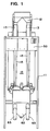
- Fig. 1 is a schematic front view showing a pulse color sorter according to the invention
- Fig. 2 is a schematic side view showing the same pulse color sorter.
- a pulse color sorter 10 having a frame 11. On the top of the frame 11, there are mounted a downwardly conical hopper 12 into which pulse to be examined is charged, a feeder 13 for feeding, under vibrations, pulse supplied naturally from the bottom of the hopper 12, and a vibrator 14 in contact with the underside of the feeders 13 for giving vibrations thereto.
- the vibrator 14 is secured to the frame 11 via a suitable vibration buffer member such as a leaf spring, a coil spring, a rubber member, for preventing direct transmission of vibrations to the frame 11.
- a shutter for controlling the supply of pulse from the hopper 12 to the feeder 13 is provided at the bottom of the hopper 12.
- the feeder 13 has an outlet which is coupled with an upper end inlet of each of chutes 15, which are mounted in the frame 11 such that it extends obliquely from the rear upper end to the front lower end of the frame 11.
- the chutes 15 are each secured to the frame 11 with an appropriate stay 16.
- the chutes 15 each has a bottom having a V-shaped sectional profile, and thus pieces of pulse which have been fed at an adequate interval by the vibrating action of each feeder 13 are fed in a row in the chute 15 to be discharged from the lower end thereof substantially at a uniform initial speed toward a first and a second detecting position to be described later.
- the hopper 12, feeders 13, vibrator 14 and chutes 15 noted above are main components of the pulse feeder as set forth in claim 1.
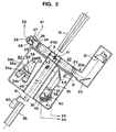
- Fig. 3 in.addition to Figs. 1 and 2, which shows, in an enlarged-scale sectional view, the detectors and ejector as essential components of the pulse color sorter according to the invention.
- the pulse under process that is discharged from the lower end of each chute 15 passes a first detecting position X1 of a first detector 20 which measures dispersed and transmitted light from the pulse under process, and then a second detecting position X2 of a second detector 30 which measures reflected light from the pulse under process, along a predetermined flow-down orbit and at a predetermined flow-down speed.
- the first and second detectors 20 and 30 output detection signals to a controller 50.
- the controller 50 executes a check according to the detection signal from each detector as to whether the pulse under process is normal or defective. If it determines the pulse as a detective one, it outputs an eject signal to an air valve 60. According to the eject signal, high pressure air is jet from a jet nozzle 61 to forcibly guide the defective piece of pulse from the normal flow-down path to a recovery chute 62.
- the pulse under process which has been determined as a normal one by the controller 50 based on the detection signals from the first and second detectors 20 and 30, is led directly to a discharge tube 65 which is provided along the flow-down orbit, without receiving high pressure air from the jet nozzle 61.
- Designated at 66 is a shutter which is held open during the normal sorting operation.
- the shutter 66 is provided for leading all the pulse to the recovery chute 62 when adjusting the machine, i.e., when making so called initial setting thereof, which is required when using the machine.
- the initial setting includes the setting of each threshold value in the controller, adjustment of brightness of lamps in the reference color plate.
- the first detector 20 includes an illumination cylinder 20A accommodating therein a light source such as a halogen lamp and a detection cylinder 20B accommodating therein a plurality of detectors, the cylinders 20A and 20B being disposed on the opposite sides of the first detecting position X1. More specifically, as shown in an enlarged-scale sectional view of Fig. 3, the illumination cylinder 20A accommodates a halogen lamp 21 disposed adjacent one end, a converging lens 23 disposed adjacent the other end, and a mirror 22 disposed at a corner for 90 degree direction change. Light from the halogen lamp 22 is converged by the lens 23 to illuminate pulse A under process arriving at the first detecting position X1.
- Light dispersed in and transmitted through the pulse A under process is directed toward the detection cylinder 20B.
- the detection cylinder 20B accommodates therein the converging lens 24 disposed on the side of the first detecting position X1.
- Light converged by the lens 24 is divided by a half mirror 25 into two light beams which are directed in directions at an angle of 90° from each other.
- One of the light beams which has reached the half mirror 25 is incident on a low-pass optical filter 26 which selectively passes only a short wavelength region of light, for instance at 700 nm.
- a sensor 27 disposed behind the low-pass optical filter 26 detects the intensity of light and outputs a detection signal S1.
- the other light beam which has reached the half mirror 25 is incident on a high-pass optical filter 28 which selectively passes only a long wavelength region of light, for instance at 1,100 nm.
- a sensor 29 disposed behind the high-pass optical filter 28 detects the intensity of light and outputs a detection signal S2.
- the detection signals S1 and S2 from the sensors 27 and 29 have different contents of information due to the separation of their wavelengths from each other, and they are supplied to the controller 50 which will be described later in detail.
- the wavelength of 700 nm which is the nominal wavelength of the low-pass optical filter 26, and the wavelength of 1,100 nm which is the nominal wavelength of the high-pass optical filter 28 are empirically obtained values of wavelength, which can provide the most pronounced difference when detecting afuratoxine in the near-infrared range.
- oil is decomposed as mold grows. Consequently, fatty acid as the decomposition product increases, and eventually there is the decomposition product solely. Accordingly, the correlation between the oil decomposition factor and light transmittance (transmitted light being reduced with increase of the decomposition product) was examined to find out the wavelengths of 700 and 1,100 nm as effective wavelengths for the sorting.
- the half mirror 25 as light splitter means may be replaced by a dichroic mirror, which reflects all light on the long wavelength side of a certain wavelength and transmits all light on the short wavelength side.
- a dichroic mirror which reflects all light on the long wavelength side of a certain wavelength and transmits all light on the short wavelength side.
- the detailed structure of the second detector 30 will now be described.
- the second detector 30 basically comprises a halogen lamp 31, a reference color cylinder 32 and a detection cylinder 33 as a set. In an actual arrangement, three sets of these components are provided at an interval of 120° around the second detecting position X2 as the center for examining the entire circumference of pulse pieces under process.
- the reference color cylinder 32 accommodates therein adjustable lamps 34a and 34b, a red and a green filter 35a and 35b, and a white plate member 36 made of milky white glass or like material.
- the detection cylinder 33 accommodates therein at least a converging lens 37, spectral means comprising a half mirror 38 which divides light converged by the lens 37 into two directions, a red filter 39 provided for one of the two light beams from the spectral means, a sensor 40 for detecting the intensity of light passed through the red filter 39 and outputting a detection signal S3, a green filter 41 provided for the other light beam from the spectral means, and a sensor 42 for detecting the intensity of light passed through the green filter 41 and outputting a detection signal S4.
- a mirror 44 may be provided in the detection cylinder 33, for 90-degree direction change of the optical axis of light from the reference color cylinder 32 and pulse under process in order to reduce the area occupied by the machine that is directed outward from the detecting position.
- Designated at 45 is a tubular transparent member which extends throughout the first and second detectors 30 and 40 to protect the machine from dust.
- a dichroic mirror may be used in place of the half mirror 38 as the spectral means used in the detection cylinder 33.
- the controller 50 comprises a first series circuit which is for processing the detection signals S1 and S2 supplied from the first detector 20, the first series circuit including a transmitted light signal processing circuit 51, a first delay circuit 52 and a first air valve circuit 53, and a second series circuit which is arranged in parallel with the first series circuit and which is for processing the detection signals S3 and S4 from the second detector 30, the second series circuit including a reflected light signal processing circuit 55, a second delay circuit 56 and a second air valve circuit 57.
- the transmitted light signal processing circuit 51 executes division of the two signals S1 and S2 from the first detector 20, which are based on dispersed and transmitted light and having different contents of information due to the separation of the two wavelengths, and it also executes comparison of the resultant value with a predetermined threshold value. If the resultant value produced in the transmitted light signal processing circuit 51 is beyond the threshold value, the first delay circuit 52 provides a delay signal corresponding to the distance L1 from the first detecting position X1 to an air valve position (see Fig. 3). According to this delay signal, the first air valve circuit 53 provides an eject signal to the air valve 60.
- the reflected light signal processing circuit 55 executes comparison of the signals S3 and S4 from the second detector 30, which are based on the reflected light, to a predetermined threshold value. If the detection signals are beyond the threshold value, the second delay circuit 56 provides a delay signal corresponding to the distance L2 from the second detecting position X2 to the air valve position (see Fig. 3). According to this delay signal, the second air valve circuit 57 provides an ejection signal to the air valve 60.
- the air valve circuits may be replaced with a single air valve circuit 53, as shown by the dashed line, which commonly receives the outputs of the first and second delay circuits 52 and 56.
- Switches SW1 and SW2 which are provided before the transmitted and reflected light signal processing circuits 51 and 55, respectively, are switches for selecting functions of the sorter.
- the switches SW1 and SW2 are both closed, it is permitted not only to execute detection for moldy pulse on the basis of the dispersed and transmitted light but also to execute detection for unripe pulse, worm-eaten pulse, etc. on the basis of the reflected light.
- the moldy pulse content may be calculated by measuring the total quantity of pulse passing the first detecting position while obtaining the accumulated quantity of moldy pulse.
- the illustrated embodiment is a two-channel color sorter as is obvious from Fig. 1.
- this number of channels is by no means limitative.
- a multiplexer may be used to use the controller commonly for the multiple channels on a time division basis. By so doing, it is possible to avoid the complication of the controller (i.e., the circuit thereof).
- pulse color sorter is for performing measurement on the basis of dispersed and transmitted light, it is of course effective for the measurement of either internally or externally moldy pulse.
- the detection of moldy pulse which has hitherto been theoretically impossible by measurement based on the reflected light, is made possible by the measurement based on dispersed and transmitted light.
- the moldy pulse is determined on the basis of a combination of two signals having different contents of information due to separation of the respective wavelengths in the near-infrared range, accurate determination is possible irrespective of the sizes of pulse pieces.
- the pulse color sorter according to the invention it is possible to provide toxicity free pulse free to the consumer, thus greatly contributing to the food safety improvement.
Landscapes
- Health & Medical Sciences (AREA)
- General Health & Medical Sciences (AREA)
- Toxicology (AREA)
- Sorting Of Articles (AREA)
Applications Claiming Priority (2)
| Application Number | Priority Date | Filing Date | Title |
|---|---|---|---|
| JP5183451A JPH0796253A (ja) | 1993-06-30 | 1993-06-30 | 豆類色彩選別機 |
| JP183451/93 | 1993-06-30 |
Publications (3)
| Publication Number | Publication Date |
|---|---|
| EP0631828A2 true EP0631828A2 (fr) | 1995-01-04 |
| EP0631828A3 EP0631828A3 (fr) | 1995-05-03 |
| EP0631828B1 EP0631828B1 (fr) | 1999-04-07 |
Family
ID=16136013
Family Applications (1)
| Application Number | Title | Priority Date | Filing Date |
|---|---|---|---|
| EP94304771A Expired - Lifetime EP0631828B1 (fr) | 1993-06-30 | 1994-06-30 | Trieuse selon la couleur pour le tri de légumineuses moisies |
Country Status (4)
| Country | Link |
|---|---|
| US (1) | US5487472A (fr) |
| EP (1) | EP0631828B1 (fr) |
| JP (1) | JPH0796253A (fr) |
| DE (1) | DE69417635T2 (fr) |
Cited By (2)
| Publication number | Priority date | Publication date | Assignee | Title |
|---|---|---|---|---|
| CN1035132C (zh) * | 1995-05-02 | 1997-06-11 | 武汉美 | 晶体谐振式小型数显电子秤 |
| WO2017202954A1 (fr) * | 2016-05-26 | 2017-11-30 | Sikora Ag | Procédé et dispositif pour examiner des produits en vrac |
Families Citing this family (20)
| Publication number | Priority date | Publication date | Assignee | Title |
|---|---|---|---|---|
| JPH07155702A (ja) * | 1993-12-01 | 1995-06-20 | Satake Eng Co Ltd | 穀粒色彩選別装置 |
| US5865990A (en) * | 1996-09-13 | 1999-02-02 | Uncle Ben's, Inc. | Method and apparatus for sorting grain |
| JP3285076B2 (ja) * | 1996-12-16 | 2002-05-27 | 株式会社サタケ | 穀粒等の色彩選別機における集塵装置 |
| JPH10300679A (ja) * | 1997-04-22 | 1998-11-13 | Satake Eng Co Ltd | 粒状物色彩選別機における光学検出装置 |
| DE69711944T2 (de) * | 1997-11-24 | 2002-11-21 | Svante Bjoerk Ab, Kungsbacka | Vorrichtung und verfahren zum sortieren von granulaten |
| AU3930000A (en) * | 1999-03-29 | 2000-10-16 | Src Vision, Inc. | Multi-band spectral sorting system for light-weight articles |
| JP4561944B2 (ja) * | 2000-06-16 | 2010-10-13 | 株式会社サタケ | 粒状物選別装置 |
| US6864970B1 (en) | 2000-10-11 | 2005-03-08 | Best N.V. | Apparatus and method for scanning products with a light beam to detect and remove impurities or irregularities in a conveyed stream of the products |
| JP2003205269A (ja) * | 2001-11-09 | 2003-07-22 | Satake Corp | 粒状物色彩選別機における光学検出手段 |
| JP2003170122A (ja) * | 2001-12-06 | 2003-06-17 | Satake Corp | 粒状物色彩選別機 |
| JP4344164B2 (ja) * | 2003-04-18 | 2009-10-14 | 株式会社サタケ | 圧電式エアバルブおよび複合圧電式エアバルブ |
| JP4438358B2 (ja) * | 2003-09-04 | 2010-03-24 | 株式会社サタケ | 表示調整機構を具えた粒状物色彩選別機 |
| US20050097021A1 (en) * | 2003-11-03 | 2005-05-05 | Martin Behr | Object analysis apparatus |
| US7173708B2 (en) * | 2003-12-05 | 2007-02-06 | Sunkist Growers Inc. | Method and apparatus for detecting damage in plant products |
| JP5407387B2 (ja) * | 2009-02-06 | 2014-02-05 | セイコーエプソン株式会社 | 測定装置 |
| US8482742B2 (en) | 2009-02-06 | 2013-07-09 | Seiko Epson Corporation | Measuring apparatus and measuring method |
| JP5795498B2 (ja) * | 2011-06-03 | 2015-10-14 | 株式会社クボタ | 粒状体選別装置 |
| JP6037125B2 (ja) * | 2013-02-18 | 2016-11-30 | 株式会社サタケ | 光学式粒状物選別機 |
| JP6333618B2 (ja) * | 2014-05-01 | 2018-05-30 | 株式会社ケット科学研究所 | 撮像装置と操作パネル式情報端末とを組み合わせた穀粒判別システム |
| US10345789B2 (en) | 2016-06-21 | 2019-07-09 | Scientific Games International, Inc. | System and method for variable perforation profiles in a stack of lottery tickets |
Family Cites Families (16)
| Publication number | Priority date | Publication date | Assignee | Title |
|---|---|---|---|---|
| US3004664A (en) * | 1957-07-09 | 1961-10-17 | Gen Precision Inc | Method and apparatus for optical analysis of a mixture of substances |
| US3802558A (en) * | 1973-04-02 | 1974-04-09 | Sortex North America | Refuse sorting and transparency sorting |
| US4096949A (en) * | 1976-06-01 | 1978-06-27 | Geosource Inc. | Apparatus for performing a three-way sort |
| JPS5478191A (en) * | 1977-12-02 | 1979-06-22 | Omron Tateisi Electronics Co | Detecting method of defect of rice grains |
| GB2142426B (en) * | 1983-06-30 | 1986-09-17 | Gunsons Sortex Ltd | Sorting machine and method |
| GB8425274D0 (en) * | 1984-10-05 | 1984-11-14 | Spandrel Etab | Signal responsive to parameter of objects |
| US5158181A (en) * | 1985-10-29 | 1992-10-27 | Bailey Roger F | Optical sorter |
| JPS62150141A (ja) * | 1985-12-25 | 1987-07-04 | Shizuoka Seiki Co Ltd | 玄米の品質判定方法 |
| DE3789015T2 (de) * | 1987-02-14 | 1994-06-23 | Satake Eng Co Ltd | Apparat zum Sortieren nach Farbe. |
| JPH0811223B2 (ja) * | 1987-02-16 | 1996-02-07 | 株式会社佐竹製作所 | 色彩選別機の光電検出装置 |
| JPS63315179A (ja) * | 1987-03-18 | 1988-12-22 | 株式会社 サタケ | 色彩選別装置 |
| US5106195A (en) * | 1988-06-09 | 1992-04-21 | Oms - Optical Measuring Systems | Product discrimination system and method therefor |
| FR2632879B1 (fr) * | 1988-06-17 | 1991-06-21 | Guerin Sarl Ets Gaby | Dispositif de tri optique d'objets selon leur couleur, en particulier de morceaux de verre |
| KR960011097B1 (ko) * | 1988-08-11 | 1996-08-20 | 가부시기가이샤 사다께세이사꾸쇼 | 미립품위 판별장치 |
| JP2651867B2 (ja) * | 1989-03-28 | 1997-09-10 | 株式会社佐竹製作所 | 樹脂ペレットの着色粒除去装置 |
| JPH0634974B2 (ja) * | 1989-10-03 | 1994-05-11 | 株式会社安西総合研究所 | 透過光を利用した選別装置 |
-
1993
- 1993-06-30 JP JP5183451A patent/JPH0796253A/ja active Pending
-
1994
- 1994-06-30 EP EP94304771A patent/EP0631828B1/fr not_active Expired - Lifetime
- 1994-06-30 DE DE69417635T patent/DE69417635T2/de not_active Expired - Fee Related
- 1994-06-30 US US08/269,109 patent/US5487472A/en not_active Expired - Fee Related
Cited By (5)
| Publication number | Priority date | Publication date | Assignee | Title |
|---|---|---|---|---|
| CN1035132C (zh) * | 1995-05-02 | 1997-06-11 | 武汉美 | 晶体谐振式小型数显电子秤 |
| WO2017202954A1 (fr) * | 2016-05-26 | 2017-11-30 | Sikora Ag | Procédé et dispositif pour examiner des produits en vrac |
| CN109311060A (zh) * | 2016-05-26 | 2019-02-05 | 斯考拉股份公司 | 用于检查松散物料的设备和方法 |
| RU2710402C1 (ru) * | 2016-05-26 | 2019-12-26 | Сикора Аг | Устройство и способ исследования сыпучего материала |
| US11249006B2 (en) | 2016-05-26 | 2022-02-15 | Sikora Ag | Device and method for investigating bulk material |
Also Published As
| Publication number | Publication date |
|---|---|
| EP0631828B1 (fr) | 1999-04-07 |
| US5487472A (en) | 1996-01-30 |
| DE69417635T2 (de) | 1999-09-02 |
| JPH0796253A (ja) | 1995-04-11 |
| EP0631828A3 (fr) | 1995-05-03 |
| DE69417635D1 (de) | 1999-05-12 |
Similar Documents
| Publication | Publication Date | Title |
|---|---|---|
| US5487472A (en) | Color sorter for sorting out moldy pulse | |
| EP0719598B1 (fr) | Appareil de tri de grains selon la couleur | |
| US5638961A (en) | Cereal grain color sorting apparatus | |
| US5538142A (en) | Sorting apparatus | |
| US5873470A (en) | Sorting apparatus | |
| US5703784A (en) | Machine vision apparatus and method for sorting objects | |
| US6013887A (en) | Color-sorting machine for granular materials | |
| US5713473A (en) | Color sorting apparatus for beans | |
| EP1314489B1 (fr) | Dispositif pour trier matières des granulés selon leur couleur, comprenant un dispositif de détection optique consistant en un capteur CCD linéaire | |
| US4120402A (en) | Color sorter including a foreign object reject system | |
| JP2010042326A (ja) | 光学式穀粒選別装置 | |
| JPS6257683A (ja) | 農産物の選別装置 | |
| US20220008959A1 (en) | Optical sorter | |
| US5508512A (en) | Sorting machine using dual frequency optical detectors | |
| US5353937A (en) | Automatic variable ejector delay time and dwell type mechanism in a sorting apparatus | |
| GB2091416A (en) | Sorting Objects | |
| US5631460A (en) | Sorting machine using dual frequency optical detectors | |
| EP0968772A2 (fr) | Une machine de tri | |
| JPH09304182A (ja) | 穀粒色彩選別機 | |
| US5278768A (en) | Autotrip operation of a sorting machine using color sorting | |
| JP4674390B2 (ja) | 玄米色彩選別方法及び玄米色彩選別装置 | |
| JP4465816B2 (ja) | 玄米色彩選別方法及び玄米色彩選別装置 | |
| JPH0114829B2 (fr) | ||
| EP0865833A2 (fr) | Arrière-plan réflecteur pour machine de tri | |
| MXPA96000339A (en) | Classification machine using detectoresempareda |
Legal Events
| Date | Code | Title | Description |
|---|---|---|---|
| PUAI | Public reference made under article 153(3) epc to a published international application that has entered the european phase |
Free format text: ORIGINAL CODE: 0009012 |
|
| AK | Designated contracting states |
Kind code of ref document: A2 Designated state(s): DE FR GB IT |
|
| PUAL | Search report despatched |
Free format text: ORIGINAL CODE: 0009013 |
|
| AK | Designated contracting states |
Kind code of ref document: A3 Designated state(s): DE FR GB IT |
|
| 17P | Request for examination filed |
Effective date: 19950412 |
|
| 17Q | First examination report despatched |
Effective date: 19970708 |
|
| GRAG | Despatch of communication of intention to grant |
Free format text: ORIGINAL CODE: EPIDOS AGRA |
|
| GRAG | Despatch of communication of intention to grant |
Free format text: ORIGINAL CODE: EPIDOS AGRA |
|
| GRAH | Despatch of communication of intention to grant a patent |
Free format text: ORIGINAL CODE: EPIDOS IGRA |
|
| GRAH | Despatch of communication of intention to grant a patent |
Free format text: ORIGINAL CODE: EPIDOS IGRA |
|
| GRAA | (expected) grant |
Free format text: ORIGINAL CODE: 0009210 |
|
| AK | Designated contracting states |
Kind code of ref document: B1 Designated state(s): DE FR GB IT |
|
| REF | Corresponds to: |
Ref document number: 69417635 Country of ref document: DE Date of ref document: 19990512 |
|
| PGFP | Annual fee paid to national office [announced via postgrant information from national office to epo] |
Ref country code: FR Payment date: 19990610 Year of fee payment: 6 |
|
| PGFP | Annual fee paid to national office [announced via postgrant information from national office to epo] |
Ref country code: GB Payment date: 19990630 Year of fee payment: 6 |
|
| PGFP | Annual fee paid to national office [announced via postgrant information from national office to epo] |
Ref country code: DE Payment date: 19990706 Year of fee payment: 6 |
|
| ET | Fr: translation filed | ||
| PLBE | No opposition filed within time limit |
Free format text: ORIGINAL CODE: 0009261 |
|
| STAA | Information on the status of an ep patent application or granted ep patent |
Free format text: STATUS: NO OPPOSITION FILED WITHIN TIME LIMIT |
|
| 26N | No opposition filed | ||
| PG25 | Lapsed in a contracting state [announced via postgrant information from national office to epo] |
Ref country code: GB Free format text: LAPSE BECAUSE OF NON-PAYMENT OF DUE FEES Effective date: 20000630 |
|
| GBPC | Gb: european patent ceased through non-payment of renewal fee |
Effective date: 20000630 |
|
| PG25 | Lapsed in a contracting state [announced via postgrant information from national office to epo] |
Ref country code: FR Free format text: LAPSE BECAUSE OF NON-PAYMENT OF DUE FEES Effective date: 20010228 |
|
| REG | Reference to a national code |
Ref country code: FR Ref legal event code: ST |
|
| PG25 | Lapsed in a contracting state [announced via postgrant information from national office to epo] |
Ref country code: DE Free format text: LAPSE BECAUSE OF NON-PAYMENT OF DUE FEES Effective date: 20010403 |
|
| PG25 | Lapsed in a contracting state [announced via postgrant information from national office to epo] |
Ref country code: IT Free format text: LAPSE BECAUSE OF NON-PAYMENT OF DUE FEES;WARNING: LAPSES OF ITALIAN PATENTS WITH EFFECTIVE DATE BEFORE 2007 MAY HAVE OCCURRED AT ANY TIME BEFORE 2007. THE CORRECT EFFECTIVE DATE MAY BE DIFFERENT FROM THE ONE RECORDED. Effective date: 20050630 |