EP0632435B1 - Appareil de mémoire magnétique - Google Patents
Appareil de mémoire magnétique Download PDFInfo
- Publication number
- EP0632435B1 EP0632435B1 EP94110081A EP94110081A EP0632435B1 EP 0632435 B1 EP0632435 B1 EP 0632435B1 EP 94110081 A EP94110081 A EP 94110081A EP 94110081 A EP94110081 A EP 94110081A EP 0632435 B1 EP0632435 B1 EP 0632435B1
- Authority
- EP
- European Patent Office
- Prior art keywords
- slider
- memory apparatus
- magnetic memory
- rigid
- sliding surface
- Prior art date
- Legal status (The legal status is an assumption and is not a legal conclusion. Google has not performed a legal analysis and makes no representation as to the accuracy of the status listed.)
- Expired - Lifetime
Links
Images


Classifications
-
- G—PHYSICS
- G11—INFORMATION STORAGE
- G11B—INFORMATION STORAGE BASED ON RELATIVE MOVEMENT BETWEEN RECORD CARRIER AND TRANSDUCER
- G11B5/00—Recording by magnetisation or demagnetisation of a record carrier; Reproducing by magnetic means; Record carriers therefor
- G11B5/48—Disposition or mounting of heads or head supports relative to record carriers ; arrangements of heads, e.g. for scanning the record carrier to increase the relative speed
- G11B5/4806—Disposition or mounting of heads or head supports relative to record carriers ; arrangements of heads, e.g. for scanning the record carrier to increase the relative speed specially adapted for disk drive assemblies, e.g. assembly prior to operation, hard or flexible disk drives
- G11B5/4813—Mounting or aligning of arm assemblies, e.g. actuator arm supported by bearings, multiple arm assemblies, arm stacks or multiple heads on single arm
-
- G—PHYSICS
- G11—INFORMATION STORAGE
- G11B—INFORMATION STORAGE BASED ON RELATIVE MOVEMENT BETWEEN RECORD CARRIER AND TRANSDUCER
- G11B11/00—Recording on or reproducing from the same record carrier wherein for these two operations the methods are covered by different main groups of groups G11B3/00 - G11B7/00 or by different subgroups of group G11B9/00; Record carriers therefor
- G11B11/10—Recording on or reproducing from the same record carrier wherein for these two operations the methods are covered by different main groups of groups G11B3/00 - G11B7/00 or by different subgroups of group G11B9/00; Record carriers therefor using recording by magnetic means or other means for magnetisation or demagnetisation of a record carrier, e.g. light induced spin magnetisation; Demagnetisation by thermal or stress means in the presence or not of an orienting magnetic field
- G11B11/105—Recording on or reproducing from the same record carrier wherein for these two operations the methods are covered by different main groups of groups G11B3/00 - G11B7/00 or by different subgroups of group G11B9/00; Record carriers therefor using recording by magnetic means or other means for magnetisation or demagnetisation of a record carrier, e.g. light induced spin magnetisation; Demagnetisation by thermal or stress means in the presence or not of an orienting magnetic field using a beam of light or a magnetic field for recording by change of magnetisation and a beam of light for reproducing, i.e. magneto-optical, e.g. light-induced thermomagnetic recording, spin magnetisation recording, Kerr or Faraday effect reproducing
- G11B11/1055—Disposition or mounting of transducers relative to record carriers
- G11B11/1058—Flying heads
-
- G—PHYSICS
- G11—INFORMATION STORAGE
- G11B—INFORMATION STORAGE BASED ON RELATIVE MOVEMENT BETWEEN RECORD CARRIER AND TRANSDUCER
- G11B5/00—Recording by magnetisation or demagnetisation of a record carrier; Reproducing by magnetic means; Record carriers therefor
- G11B5/48—Disposition or mounting of heads or head supports relative to record carriers ; arrangements of heads, e.g. for scanning the record carrier to increase the relative speed
- G11B5/58—Disposition or mounting of heads or head supports relative to record carriers ; arrangements of heads, e.g. for scanning the record carrier to increase the relative speed with provision for moving the head for the purpose of maintaining alignment of the head relative to the record carrier during transducing operation, e.g. to compensate for surface irregularities of the latter or for track following
Definitions
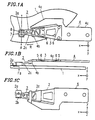
- the slider assembly 2 includes a slider part 2a at the end thereof in the positive x -axis direction, and a rigid part 2c unified into the slider part 2a.
- the slider part 2a is provided with a coil 8 and a magnetic core 7 on which the coil 8 is wound.
- the slider part 2a has a projecting portion on its bottom surface facing the magneto-optical disk 1.
- the projecting portion has a spherical surface 2b (radius: 10 mm).
- the rigid part 2c is partially bored into a truss structure, as shown in Figure 1A, so as to lighten the weight while maintaining its rigidity.
- the slider assembly 2 is made of a resin, and the slider part 2a, the spherical surface 2b and the rigid part 2c are integrally formed of the resin.
- the center yoke top 7b cannot be located within the region R1.
- the center yoke top 7b When being on the plane S1 and located in the region R2, i.e., a region outside the curve C1 , the center yoke top 7b inevitably comes into contact with the sliding surface 1d . Accordingly, the center yoke top 7b should be located outside the region R1 and inside the region R2.
- Figure 3 shows a possible location of the center yoke top 7b.
- the center yoke top 7b is generally long enough in the y -axis direction to cover a tracking range of an actuator for the objective lens 11.
- the center yoke top 7b is located in the vicinity of the origin O which is a standard contact point. The reason is that the shift in the distance, which is a distance in the z -axis direction, between the center yoke top 7b and the recording layer 1b becomes smaller as the distance between the center yoke top 7b and the origin O is smaller, when the magneto-optical disk 1 is inclined. In this case, a stable recording operation can be performed. Accordingly, it is optimum that the center yoke top 7b is located as shown in Figure 3.
- the slider part 2a shown in Figure 2 should be configured so that the plane S1 is located within the curve C1, and the planes S2 and S3 are located within the curves C2 and C3, respectively. Due to this locational relationship, the bottom part of the slider part 2a can be prevented from being in contact with the sliding surface 1d.
- Figure 4 is a side view showing a state of virtual assemblage of the magneto-optical disk 1.
- the blade spring 3 becomes flat with no external force, and the slider part 2a is shifted downward in accordance with inclination of the slope 5.
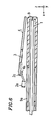
- Figure 5 is a side view showing a state of real assemblage of the magneto-optical disk 1.
- the blade spring 3 is elastically deformed, so that the hook part 4b is in contact with the rigid part 2c. Accordingly, the slider part 2a is not so shifted downward with no external force, compared with the state as shown Figure 4.
- Figure 1B shows a state where the blade spring 3 provides the slider part 2a (projecting portion 2b ) with a standard pressing force.
- this state is referred to as "a standard deformation state”.
- an angle formed by the slope 5 provided on the rigid part 2c and the slope 5 provided on the fixing plate 4 is ⁇ or ⁇ - ⁇ ( ⁇ ⁇ ⁇ - ⁇ ).
- the slope 5 of the rigid part 2c is arranged so as to have an angle of approximately ⁇ / 2 from the standard plane in the standard operation state.
- the slope 5 provided on the fixing plate 4 is arranged so as to have an angle of approximately - ⁇ /2 from the standard plane in the standard operation state.
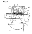
- Figure 7 shows a recording operation of the magnetic head.
- the laser beam 10 is focused on a recording track of the recording layer 1b by the objective lens 11.
- magnetic fluxes ⁇ are generated in the magnetic core 7 made of ferrite.
- the magnetic fluxes ⁇ are generated between the center yoke top 7b and each of the side yoke tops 7d as shown in Figure 6.
- a sufficient number of magnetic fluxes ⁇ for recording pass through the recording layer 1b in the vicinity of the center yoke top 7b.
- an inexpensive flat-plate shaped blade spring 3 can be employed in place of a conventional spring member which is made by a precise bending process.
- the heights of the slopes 5 are set so that the bottom end of the blade spring 3 does not project from the fixing part 4c when it is deformed during operation.
- the hook part 4b By virtue of the hook part 4b, the amount of lifting of the magnetic head assembly can be restrained, greatly contributing to compactness of the device.
Landscapes
- Supporting Of Heads In Record-Carrier Devices (AREA)
Claims (21)
- Dispositif de mémoire magnétique utilisé pour un moyen de stockage d'informations (1) incluant une surface glissante (1d), comprenant :caractérisé en ce queun ensemble de tête comprenant :un moyen ce création de champ magnétique (7) possédant un pôle magnétique destiné à fournir un champ magnétique au moyen de stockage d'informations (1) ;un moyen formant pièce glissante accouplé au moyen de création de champ magnétique (7), le moyen formant pièce glissante possédant une partie en saillie qui est en saillie vers le moyen de stockage d'informations (1) ;un moyen de charge (2, 3, 4) accouplé au moyen formant pièce glissante, le moyen de charge (2, 3, 4) fournissant une force de poussée au moyen formant pièce glissante dans une direction perpendiculaire à la surface glissante (1d), et poussant la partie en saillie sur la surface glissante (1d) ;dans lequel une surface de la partie en saillie du moyen formant pièce glissante (2a) inclut une partie d'une surface sphérique (2b) ; de telle façon, queun emplacement de la surface inférieure du pôle magnétique sur un plan virtuel (S1) incluant la surface inférieure du pôle magnétique est à l'extérieur d'une région de contact (R1) où la partie en saillie du moyen formant pièce glissante et la surface glissante (1d) du moyen de stockage d'informations (1) peuvent être en contact l'une avec l'autre durant l'opération ; et
l'emplacement de la surface inférieure du pôle magnétique sur le plan virtuel (S1) incluant la surface inférieure du pôle magnétique est à l'intérieur d'une région de croisement (R2) où le plan virtuel (S1) et la surface coulissante (1d) peuvent se croiser. - Dispositif de mémoire magnétique selon la revendication 1, dans lequel le moyen de charge inclut :une partie de fixation (4c) destinée à fixer le moyen de charge (2, 3, 4) sur un corps séparé du moyen de stockage d'informations (1) ;une partie de création de charge (3) destinée à créer la force de poussée dans une direction sensiblement perpendiculaire à la surface glissante (1d) ; etune partie rigide (2c) composée d'une matière sensiblement rigide,dans lequel la partie de fixation (4c), la partie de création de charge (3), la partie rigide (2c), et le moyen formant pièce glissante (2a) sont reliés en série sensiblement dans cet ordre, et dans lequel une direction allant de la partie de fixation (4c) au moyen formant pièce glissante (2a) est sensiblement parallèle à la direction du glissement.
- Dispositif de mémoire magnétique selon la revendication 2, dans lequel le moyen formant pièce glissante (2a) et la partie rigide (2c) du moyen de charge (2, 3, 4) sont formés d'un seul tenant et composés de la même résine.
- Dispositif de mémoire magnétique selon la revendication 2, dans lequel la partie de création de charge (3) du moyen de charge (2, 3, 4) est un corps élastique (3) ayant une forme sensiblement plate sans force extérieure quelconque ; et
le corps élastique est déformé élastiquement de manière à obtenir une forme convexe vers la surface glissante (1d) du moyen de stockage d'informations (1), et est accouplé entre la partie rigide (2) et la partie de fixation (4c) du moyen de charge (2, 3, 4), procurant par ce moyen une force élastique provenant du corps élastique (3) à la partie en saillie en tant que force de poussée. - Dispositif de mémoire magnétique selon la revendication 4, dans lequel le corps élastique (3) est un ressort métallique à lame ayant une forme de plaque plate.
- Dispositif de mémoire magnétique selon la revendication 4, dans lequel le corps élastique (3) inclut :une première partie de fixation devant être fixée à la partie rigide (2c) ; etune seconde partie de fixation devant être fixée à la partie de fixation (4c),dans lequel un état du corps élastique (3) lorsqu'il procure une force de poussée standard à la partie en saillie est défini en tant qu'état de déformation standard, et dans le cas où un angle foré par un plan de contact de la première partie de fixation et par un plan de contact de la seconde partie de fixation dans l'état de déformation standard est , la surface glissante (1d) dans l'état de fonctionnement standard est définie en tant que plan de référence ; et dans lequella première partie de fixation est fixée à la partie rigide (2c) en formant un angle d'environ /2 par rapport au plan de référence dans l'état de fonctionnement standard, et dans lequel la seconde pièce de fixation est fixée à la partie de fixation (4c) en formant un angle d'environ - /2 par rapport au plan de référence dans l'état de fonctionnement standard.
- Dispositif de mémoire magnétique selon la revendication 6, dans lequel la partie rigide (2c) et la partie de fixation (4c) sont composées d'une résine et le corps élastique (3) est composé d'un ressort métallique à lame ayant une forme de plaque plate ;
une face de fixation de la partie rigide ayant presque un plan plat est prévue sur la partie rigide (2c) pour la fixation de la première face de fixation, la face de fixation de la partie rigide formant un angle d'environ /2 par rapport au plan de référence ; une face de fixation de la partie fixée ayant presque une forme de plan est prévue sur la partie de fixation (4c) pour fixer la seconde face de fixation, la face de fixation de la partie fixée formant un angle d'environ - /2 par rapport au plan de référence ; et les ressorts métalliques à lame (3) sont fixés respectivement à la face de fixation de la partie rigide et la face de fixation de la partie fixe gràce à un moyen de rivetage en résine 6 tel qu'une fusion ultrasonique de résine. - Dispositif de mémoire magnétique selon la revendication 2, dans lequel la partie de fixation (4c) possède une surface inférieure qui est presque parallèle à la surface glissante (1d) dans un état de fonctionnement standard, la surface inférieure faisant face à la surface glissante (1d) au voisinage du corps élastique (3) ; et au moins dans l'état de fonctionnement standard, la première partie de fixation et la seconde partie de fixation sont positionnées de façon appropriée de sorte qu'un point du corps élastique (3) qui est le plus proche de la surface glissante (1d) n'est pas en saillie à partir de la surface inférieure dans le côté de la partie de fixation (4c).
- Dispositif de mémoire magnétique selon la revendication 2,dans lequel la partie de création de charge (3) est un ressort métallique ;la partie formant pièce glissante (2a), la partie rigide (2c), et la partie de fixation (4c) sont composées d'une matière résineuse ; etla partie de création de charge (3) est formée entre la partie rigide (2c) et la partie de fixation (4c) au moyen d'un procédé de formation de pièce encastrée ou de pièce extérieure.
- Dispositif de mémoire magnétique selon la revendication 2,dans lequel la partie de création de charge (3) est un ressort composé dans une matière résineuse ;la partie formant pièce glissante (2a), la partie rigide (2c), et la partie de fixation (4c) sont composées dans une matière résineuse ; etla partie de création de charge (3) la partie formant pièce glissante (2a), et la partie rigide (2c) forment une structure d'un seul tenant.
- Dispositif de mémoire magnétique selon la revendication 10, dans lequel un fil métallique est formé dans la partie de création de charge (3) au moyen d'un procédé de formation de pièce encastrée ou de pièce extérieure, gràce à quoi le fil métallique et la partie de création de charge (3) forment une structure d'un seul tenant.
- Dispositif de mémoire magnétique selon la revendication 2, dans lequel la partie de création de charge (3) a une configuration dans laquelle un fil métallique est formé au moyen d'un procédé de formation de pièce encastrée ou de pièce extérieure pour obtenir une structure de charnière composée de matière résineuse ;la partie formant pièce glissante (2a), la partie rigide (2c), et la partie de fixation (4c) sont réalisées dans une matière composée de résine ; etla partie de création de charge (3), la partie formant pièce glissante (2a), la partie rigide (2c), et la partie de fixation (4c) forment une structure d'un seul tenant.
- Dispositif de mémoire magnétique selon la revendication 1, dans lequel le pôle magnétique est prévu au niveau d'une direction radialement vers l'extérieur du moyen de stockage d'informations (1) par rapport à la surface de la partie en saillie du moyen formant pièce glissante.
- Dispositif de mémoire magnétique selon la revendication 13,dans lequel un rayon de la surface sphérique (2b) de la partie en saillie est environ égal à 10 mm, et un niveau de saillie de la pièce en saillie est égal à environ 50 µm ; etle pôle magnétique est situé dans une plage allant d'environ 0,4 mm à environ 1,4 mm le long d'une direction radiale du moyen de stockage d'informations (1) à partir d'une crête de la partie en saillie du côté d'une position radialement vers l'extérieur du moyen de stockage d'informations (1).
- Dispositif de mémoire magnétique selon la revendication 2,dans lequel une pièce formant bras (4a) est étendue sensiblement le long d'une direction de glissement depuis la partie de fixation (4c), et une partie formant crochet (4b) est prévue sur une extrémité en bout de la partie formant bras (4a) ;la partie formant crochet (4b) est située entre la partie rigide (2c) et la surface glissante (1d) lorsque la partie en saillie est en contact avec le moyen de stockage d'informations (1) alors que l'ensemble de tête magnétique fonctionne ; dans lequel la partie formant crochet (4b) ne vient pas en contact avec une partie quelconque à l'exclusion de la partie de fixation (4c) ;et la partie formant crochet (4b) vient en contact avec la partie rigide (2c) au moyen de la force de poussée créée par la partie de création de charge (3) alors que la partie en saillie est écartée de la surface glissante (1d).
- Dispositif de mémoire magnétique selon la revendication 15,
dans lequel la partie formant crochet (4b) est composé d'un élément en forme de baguette ou de plaque qui est presque parallèle à la surface glissante (1d) et qui s'étend dans une direction sensiblement perpendiculaire à une direction de glissement. - Dispositif de mémoire magnétique selon la revendication 1,
dans lequel un emplacement de la partie formant pièce glissante (2a) se trouve dans un espace limité qui n'inclut pas le moyen de stockage d'informations (1), l'espace étant l'un des deux espaces divisés par une enveloppe intérieure d'un groupe de plans qui est formée par la surface glissante (1d). - Dispositif de mémoire magnétique selon la revendication 17, dans lequel un plan incluant la surface glissante (1d) durant le fonctionnement est indiqué en tant que plan DO et des plans écartés de la surface glissante (1d) sont indiqués respectivement en tant que plans D1 et D2 dépendant respectivement d'une distance d1 à dn depuis le plan DO vers les plans correspondants D1 à Dn, et les plans respectifs D1 à Dn ainsi que la partie de la surface sphérique formant les lignes de croisement C1 à Cn en tant que conséquence de la fluctuation ou de l'inclinaison de la surface glissante, les plans de la partie formant pièce glissante faisant face chacun à la surface glissante (1d) sont des plans S1 à Sn dépendant d'une distance d1 à dn depuis le plan DO et une région R1 à Rn correspondant à chaque plan Si est limitée à l'intérieur de la ligne de croisement correspondante Ci.
- Dispositif de mémoire magnétique selon la revendication 1, dans lequel une partie de contact formée lorsque la partie en saillie vient en contact avec le moyen de stockage d'informations (1) est une région de contact unique ayant une limite qui ne comprend aucune partie en ligne droite ou aucune partie concave.
- Dispositif de mémoire magnétique selon la revendication 1, dans lequel le moyen de création de champ magnétique (7) est situé à l'intérieur du moyen formant pièce glissante.
- Dispositif de mémoire magnétique selon la revendication, 1, dans lequel l'emplacement de la surface inférieure du pôle magnétique sur le plan virtuel (S1) est décalé latéralement par rapport à la région de contact (R1) dans une direction parallèle à la surface glissante (1d) du moyen de stockage d'informations (1).
Applications Claiming Priority (3)
| Application Number | Priority Date | Filing Date | Title |
|---|---|---|---|
| JP160533/93 | 1993-06-30 | ||
| JP16053393 | 1993-06-30 | ||
| JP16053393 | 1993-06-30 |
Publications (3)
| Publication Number | Publication Date |
|---|---|
| EP0632435A2 EP0632435A2 (fr) | 1995-01-04 |
| EP0632435A3 EP0632435A3 (fr) | 1995-03-08 |
| EP0632435B1 true EP0632435B1 (fr) | 1999-08-25 |
Family
ID=15717035
Family Applications (1)
| Application Number | Title | Priority Date | Filing Date |
|---|---|---|---|
| EP94110081A Expired - Lifetime EP0632435B1 (fr) | 1993-06-30 | 1994-06-29 | Appareil de mémoire magnétique |
Country Status (3)
| Country | Link |
|---|---|
| US (1) | US5600515A (fr) |
| EP (1) | EP0632435B1 (fr) |
| DE (1) | DE69420208T2 (fr) |
Families Citing this family (9)
| Publication number | Priority date | Publication date | Assignee | Title |
|---|---|---|---|---|
| US5602699A (en) * | 1995-06-29 | 1997-02-11 | Read-Rite Corporation | Gimbal assembly of a magnetic head suspension |
| JPH09288874A (ja) * | 1995-11-16 | 1997-11-04 | Hutchinson Technol Inc | 磁気ヘッドサスペンション及び磁気ヘッドの浮動高さを調整するためのサスペンション負荷調整方法 |
| US6154952A (en) * | 1998-04-22 | 2000-12-05 | Hutchinson Technology, Inc. | Attachment isolation structures for adjusting head slider static attitude |
| US6426850B1 (en) * | 1998-07-01 | 2002-07-30 | Matsushita Electric Industrial Co., Ltd. | Converter support structure |
| KR20010102169A (ko) * | 1999-12-17 | 2001-11-15 | 요트.게.아. 롤페즈 | 3개의 브리지를 갖는 액추에이터를 사용하여 위치결정하는방법 |
| USD507565S1 (en) * | 2002-09-26 | 2005-07-19 | Matsushita Electric Industrial Co., Ltd. | Magnetic head suspension |
| USD504424S1 (en) * | 2002-09-26 | 2005-04-26 | Matsushita Electric Industrial Co., Ltd. | Magnetic head suspension |
| USD505419S1 (en) * | 2002-09-26 | 2005-05-24 | Matsushita Electric Industrial Co., Ltd. | Magnetic head suspension |
| US7525767B2 (en) | 2006-02-21 | 2009-04-28 | Hitachi Global Storage Technologies Netherlands B.V. | System for low profile termination with robust alignment for wireless suspension in hard disk drive |
Family Cites Families (16)
| Publication number | Priority date | Publication date | Assignee | Title |
|---|---|---|---|---|
| US4058846A (en) * | 1976-06-21 | 1977-11-15 | International Business Machines Corporation | Grounded transducer for magnetic record disks |
| US4167765A (en) * | 1978-07-27 | 1979-09-11 | International Business Machines Corporation | Transducer suspension mount apparatus |
| US4420780A (en) * | 1981-08-17 | 1983-12-13 | International Business Machines | Self-loading magnetic head air bearing slider |
| CA1215778A (fr) * | 1983-05-19 | 1986-12-23 | James K. Knudsen | Ensemble transducteur-curseur a surfaces de rails de suspension a air arrondies |
| JPS60167173A (ja) * | 1984-02-09 | 1985-08-30 | Nec Corp | ヘツドスライダ加圧支持機構 |
| US5185683A (en) * | 1987-12-21 | 1993-02-09 | Hutchinson Technology, Inc. | Suspension arm mounting assembly |
| JPH02235213A (ja) * | 1989-03-08 | 1990-09-18 | Nec Corp | 磁気ヘッド |
| US5006946A (en) * | 1989-04-19 | 1991-04-09 | Tdk Corporation | Flexible polymeric resinous magnetic head supporting device |
| JPH03185618A (ja) * | 1989-12-14 | 1991-08-13 | Nec Gumma Ltd | 磁気ヘッドおよびその製造方法 |
| JPH03276475A (ja) * | 1990-03-27 | 1991-12-06 | Matsushita Electric Ind Co Ltd | 磁気ディスク装置 |
| US5333085A (en) * | 1990-11-06 | 1994-07-26 | Seagate Technology, Inc. | Read/write gimbal with limited range of motion |
| JPH04263148A (ja) * | 1991-02-18 | 1992-09-18 | Mitsubishi Electric Corp | 光磁気記録装置用磁気ヘッド |
| JP3186147B2 (ja) * | 1991-11-21 | 2001-07-11 | ソニー株式会社 | 光磁気ディスク記録再生装置及び磁界変調ヘッド機構 |
| JP3496223B2 (ja) * | 1991-12-13 | 2004-02-09 | ソニー株式会社 | 光磁気記録用摺動型磁気ヘッド |
| JP2813261B2 (ja) * | 1992-02-14 | 1998-10-22 | シャープ株式会社 | 光磁気ディスク用磁気ヘッド装置及び光磁気記録再生装置 |
| JP2952455B2 (ja) * | 1992-10-30 | 1999-09-27 | ミネベア株式会社 | 浮動磁気ヘッド |
-
1994
- 1994-06-28 US US08/267,876 patent/US5600515A/en not_active Expired - Fee Related
- 1994-06-29 DE DE69420208T patent/DE69420208T2/de not_active Expired - Fee Related
- 1994-06-29 EP EP94110081A patent/EP0632435B1/fr not_active Expired - Lifetime
Also Published As
| Publication number | Publication date |
|---|---|
| DE69420208T2 (de) | 2000-03-23 |
| US5600515A (en) | 1997-02-04 |
| EP0632435A2 (fr) | 1995-01-04 |
| EP0632435A3 (fr) | 1995-03-08 |
| DE69420208D1 (de) | 1999-09-30 |
Similar Documents
| Publication | Publication Date | Title |
|---|---|---|
| EP0768655B1 (fr) | Tête magnétique du type glissant pour l'enregistrement magnéto-optique | |
| US6996033B2 (en) | Optical path for a thermal-assisted magnetic recording head | |
| US6134076A (en) | Adjustment feature for load/unload alignment of multiple disk stack ramp assembly | |
| EP0549144B1 (fr) | Tête magnétique pour enregistrement magnéto-optique | |
| US5600515A (en) | Sliding type magnetic head assembly having a spherical contact surface offset from a magnetic pole | |
| US8102627B2 (en) | Slider suspension assembly having limiter tab passing through load beam hole both within slider silhouette | |
| JP3895471B2 (ja) | レンズアクチュエータ | |
| JP5469484B2 (ja) | 近接場光利用ヘッドジンバルアセンブリ及びそれを備えた情報記録再生装置 | |
| JP3353328B2 (ja) | 光磁気記録用摺動型磁気ヘッド | |
| US6552875B1 (en) | Suspension design for improving the curing process for head bonding application and method for same | |
| JP3630719B2 (ja) | 磁気ヘッド構造体 | |
| US6044043A (en) | Magneto-optical head capable of operation under inclination of the disc | |
| JP3503226B2 (ja) | 光磁気記録用摺動型磁気ヘッド | |
| JP3379149B2 (ja) | 浮上式光ヘッド及び光記録再生装置 | |
| US6426850B1 (en) | Converter support structure | |
| Kim et al. | PCMCIA like ultra small form factor optical drive | |
| JPH1116223A (ja) | 磁気ヘッド構造体 | |
| JP3190134B2 (ja) | 摺動型磁気ヘッド用サスペンションおよび摺動型磁気ヘッド | |
| US6445648B2 (en) | Magnetic field generator and magneto-optical storage device using the same | |
| JPH05120756A (ja) | 光磁気記録再生装置用磁気ヘツド及びその調整方法 | |
| JPWO2004013856A1 (ja) | 光ディスク媒体及びハブ | |
| JP2001167543A (ja) | 磁気ヘッド支持機構 | |
| JP2003317299A (ja) | 光学ヘッドおよび光ディスク装置 | |
| JPH07210914A (ja) | 光磁気記録用摺動型磁気ヘッド | |
| JP2004206881A (ja) | 記録再生装置 |
Legal Events
| Date | Code | Title | Description |
|---|---|---|---|
| PUAI | Public reference made under article 153(3) epc to a published international application that has entered the european phase |
Free format text: ORIGINAL CODE: 0009012 |
|
| AK | Designated contracting states |
Kind code of ref document: A2 Designated state(s): DE FR GB |
|
| PUAL | Search report despatched |
Free format text: ORIGINAL CODE: 0009013 |
|
| 17P | Request for examination filed |
Effective date: 19941124 |
|
| AK | Designated contracting states |
Kind code of ref document: A3 Designated state(s): DE FR GB |
|
| 17Q | First examination report despatched |
Effective date: 19970818 |
|
| GRAG | Despatch of communication of intention to grant |
Free format text: ORIGINAL CODE: EPIDOS AGRA |
|
| GRAG | Despatch of communication of intention to grant |
Free format text: ORIGINAL CODE: EPIDOS AGRA |
|
| GRAH | Despatch of communication of intention to grant a patent |
Free format text: ORIGINAL CODE: EPIDOS IGRA |
|
| GRAH | Despatch of communication of intention to grant a patent |
Free format text: ORIGINAL CODE: EPIDOS IGRA |
|
| GRAA | (expected) grant |
Free format text: ORIGINAL CODE: 0009210 |
|
| AK | Designated contracting states |
Kind code of ref document: B1 Designated state(s): DE FR GB |
|
| REF | Corresponds to: |
Ref document number: 69420208 Country of ref document: DE Date of ref document: 19990930 |
|
| ET | Fr: translation filed | ||
| PLBE | No opposition filed within time limit |
Free format text: ORIGINAL CODE: 0009261 |
|
| STAA | Information on the status of an ep patent application or granted ep patent |
Free format text: STATUS: NO OPPOSITION FILED WITHIN TIME LIMIT |
|
| 26N | No opposition filed | ||
| REG | Reference to a national code |
Ref country code: GB Ref legal event code: IF02 |
|
| PGFP | Annual fee paid to national office [announced via postgrant information from national office to epo] |
Ref country code: FR Payment date: 20040608 Year of fee payment: 11 |
|
| PGFP | Annual fee paid to national office [announced via postgrant information from national office to epo] |
Ref country code: GB Payment date: 20040623 Year of fee payment: 11 |
|
| PGFP | Annual fee paid to national office [announced via postgrant information from national office to epo] |
Ref country code: DE Payment date: 20040708 Year of fee payment: 11 |
|
| PG25 | Lapsed in a contracting state [announced via postgrant information from national office to epo] |
Ref country code: GB Free format text: LAPSE BECAUSE OF NON-PAYMENT OF DUE FEES Effective date: 20050629 |
|
| PG25 | Lapsed in a contracting state [announced via postgrant information from national office to epo] |
Ref country code: DE Free format text: LAPSE BECAUSE OF NON-PAYMENT OF DUE FEES Effective date: 20060103 |
|
| PG25 | Lapsed in a contracting state [announced via postgrant information from national office to epo] |
Ref country code: FR Free format text: LAPSE BECAUSE OF NON-PAYMENT OF DUE FEES Effective date: 20060228 |
|
| GBPC | Gb: european patent ceased through non-payment of renewal fee |
Effective date: 20050629 |
|
| REG | Reference to a national code |
Ref country code: FR Ref legal event code: ST Effective date: 20060228 |