EP0633528A2 - Maintenance d'un système de traitement de données - Google Patents
Maintenance d'un système de traitement de données Download PDFInfo
- Publication number
- EP0633528A2 EP0633528A2 EP19940109971 EP94109971A EP0633528A2 EP 0633528 A2 EP0633528 A2 EP 0633528A2 EP 19940109971 EP19940109971 EP 19940109971 EP 94109971 A EP94109971 A EP 94109971A EP 0633528 A2 EP0633528 A2 EP 0633528A2
- Authority
- EP
- European Patent Office
- Prior art keywords
- processor
- processing system
- data processing
- storage
- data
- Prior art date
- Legal status (The legal status is an assumption and is not a legal conclusion. Google has not performed a legal analysis and makes no representation as to the accuracy of the status listed.)
- Withdrawn
Links
Images

Classifications
-
- G—PHYSICS
- G06—COMPUTING OR CALCULATING; COUNTING
- G06F—ELECTRIC DIGITAL DATA PROCESSING
- G06F11/00—Error detection; Error correction; Monitoring
-
- G—PHYSICS
- G06—COMPUTING OR CALCULATING; COUNTING
- G06F—ELECTRIC DIGITAL DATA PROCESSING
- G06F11/00—Error detection; Error correction; Monitoring
- G06F11/30—Monitoring
- G06F11/3003—Monitoring arrangements specially adapted to the computing system or computing system component being monitored
- G06F11/3034—Monitoring arrangements specially adapted to the computing system or computing system component being monitored where the computing system component is a storage system, e.g. DASD based or network based
-
- G—PHYSICS
- G06—COMPUTING OR CALCULATING; COUNTING
- G06F—ELECTRIC DIGITAL DATA PROCESSING
- G06F11/00—Error detection; Error correction; Monitoring
- G06F11/30—Monitoring
- G06F11/3051—Monitoring arrangements for monitoring the configuration of the computing system or of the computing system component, e.g. monitoring the presence of processing resources, peripherals, I/O links, software programs
-
- G—PHYSICS
- G06—COMPUTING OR CALCULATING; COUNTING
- G06F—ELECTRIC DIGITAL DATA PROCESSING
- G06F11/00—Error detection; Error correction; Monitoring
- G06F11/30—Monitoring
- G06F11/3055—Monitoring arrangements for monitoring the status of the computing system or of the computing system component, e.g. monitoring if the computing system is on, off, available, not available
-
- G—PHYSICS
- G06—COMPUTING OR CALCULATING; COUNTING
- G06F—ELECTRIC DIGITAL DATA PROCESSING
- G06F11/00—Error detection; Error correction; Monitoring
- G06F11/006—Identification
Definitions
- the present invention relates to the maintenance of a data processing system. More particularly the present invention relates to a method for determining the topology (or structure) of a storage subsystem of a data processing system, monitoring the status of the subsystem and automatically responding to perturbations in the subsystem.
- DASD direct access storage devices
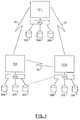
- FIG. 1 An example of an interconnected data processing system is shown in Figure 1.
- the central computer system 10A is connected to remote target computer systems 10B and 10C.
- the computer systems 10A, 10B and 10C have associated DASD storage i.e. DASDs 30A, 30B and 30C are associated with the processor of 10A via I/O controller 40A.
- DASDs 30D, 30E, 30F and 30C are associated with the processor of 10B via I/O controller 40B.
- DASD 30C is shared between processor 10A and 10C. In such a system both 10A and 10B may be aware that DASD 30C is shareable but, neither processor can determine the identity of the other processor.
- Each DASD has a unique serial number or physical identifier associated with it. This physical identifier is not actually utilised by the processor but is used by service engineers as an address for locating the physical position of a DASD for the purpose of replacing it or performing maintenance on it.
- the processor communicates with storage space on a DASD by means of a logical address. The actual physical positions and physical connections of DASDs are not known by the processor.
- the present invention provides a method for managing a data processing system including determining the topology of a storage subsystem of the data processing system by the steps of: reading identification data representing a processor of the data processing system; reading identification data representing an I/O controller associated with the processor; reading identification data representing a storage element of the storage subsystem associated with the I/O controller and processor; storing the identification data in a database; and repeating each of the reading steps and storing step for each storage element of the storage subsystem of the data processing system thereby producing a topology database from which the data processing system may identify the physical connections of a storage element of the storage subsystem.
- the present invention provides a data processing system comprising: one or more processors; at least one storage subsystem associated with each respective processor; an I/O controller associated with each respective processor for controlling data transfer between the processor and associated storage subsystems; means for reading identification data representing one of the processors; means for reading identification data representing an I/O controller associated with the processor; means for reading identification data representing an element of one of the subsystems associated with the processor; means for storing the identification data in a topology database whereby the data processing system may identify the physical connections of a storage element of the storage subsystem.
- the present invention addresses the needs of storage administrators and operators to control and manage the storage subsystems effectively and efficiently.
- operators are re-active and respond to out-of-line situations in real-time, whereas storage administrators are pro-active and need to monitor the storage subsystem to detect trends and predict the need to upgrade and reconfigure.
- Operators issue commands to make temporary changes to running systems whereas storage administrators use batch jobs to gather data and make lasting changes.
- the present invention is applicable to a single processor (either a uniprocessor or a multiprocessor) or two or more intercommunicating processor complexes. It is also applicable to two or more processor complexes that share one or more direct access storage devices with non-removable media and/or control units for DASD devices with non-removable media.
- the operating system controlling the complex or complexes is the IBM Multiple Virtual Storage (MVS) operating system produced by International Business Machines Corporation.
- MVS IBM Multiple Virtual Storage
- EREP Environmental Record Editing and Printing Program
- the MVS operating system (or control program) is responsible for controlling use of system resources such as DASD and other I/O devices.
- An example of such DASDs are the 3390 DASDs produced by International Business Machines Corporation.
- a central computer system 10A such as the IBM 3090 computer system is attached by communication lines 20 to local or remote target computer systems 10B and 10C.
- Most mainframe operating systems an example being the Multiple Virtual Storage (MVS) operating system, monitor every attached I/O device and record error data on a System Error Recording Data Set (ERDS).
- MVS Multiple Virtual Storage
- ERDS System Error Recording Data Set
- FIG. 2 shows the operation of a computer system in accordance with the present invention.
- the central system shown as 10A in Figure 1 corresponds to the central system 204 of figure 2 and the target systems 10B and 10C correspond to target systems 202.
- DASDs 30A to 30I of Figure 1 are shown at 211 in Figure 2.
- the ERDS data includes the I/O device sense bytes which are intended to assist service engineers in diagnosing errors and identifying failing components. This data is sent 201 from the target system or systems 202 as a stream to the central system 203.
- a data analysis program 204 exploits the device identification data contained in the ERDS data streams by using it to automatically build a system model 205. This model is both descriptive and normative. It:
- Copies of the model 205 are transmitted over the communication lines to reside on the target systems at 210.
- Monitoring programs 212 on the target systems perform the following functions:
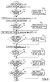
- FIG. 3 A more detailed description of the database creation is shown in Figure 3.
- data containing information about a DASD volume is read into the central processor, shown at 203 in Figure 2, from the System Error Recording Data Set (ERDS).
- ERDS System Error Recording Data Set
- Data representing the processor identifier is extracted from the ERDS record at step 302, then a check is made at 303 to see if an entry for this processor already exists in the database. If an entry does not exist then one is created at 304. A pointer to this processor entry is then saved making it the current processor entry at 305.
- the control unit identifier is extracted from the ERDS record, and at 307 a check is made to see if an entry for this control unit already exists in the database.
- An appropriate entry is made at step 308 if one does not already exist. A pointer to this control unit entry is then saved making it the current control unit entry at 309.
- the current control unit entry is checked to see if it contains the current processor pointer. If it does not, the current processor pointer is added to the control unit entry at 311.
- the DASD unit identifier is extracted from the ERDS record, and at 313 a check is made to see if an entry for this DASD unit already exists in the database. An appropriate entry is made at step 314 if one does not already exist.
- the current DASD unit entry is checked to see if it contains the current processor pointer. If it does not, the current processor pointer is added to the DASD unit entry at 316.
- the current DASD unit entry is checked to see if it contains the current control unit pointer. If it does not, the current control unit pointer is added to the DASD unit entry at 318. This process is repeated for each record in the ERDS and, on completion, the database contains entries for each processor, control unit and DASD unit in the system, together with details of the connection topology.
- the newly created database is preferably stored on disk as three separate files, one for the processor identifier, one for the control unit identifier and one for the volume identifier.
- this database of the topology of the complete system is utilised to store additional information. Additional fields are created relating to the status of the system.
- the desired status of individual DASD volumes in the system is input to the database manually and checks can be run continuously or on command to ascertain the current operating status of an individual DASD.
- Such fields may relate to the fastwrite status of a DASD device.
- the operating system of a data processing system issues a command for data to be written to a DASD the data is normally first written to a cache memory, which generally has the fastest access time of the hierarchy of data storage devices of a computer system, then transferred to DASD in time.
- the fastwrite status field indicates whether a data set is currently stored in cache memory or in DASD or whether it is being transferred between the two.
- the topology database is read by the analysis program (indicated at 204 in Figure 2) which can issue commands to the operating system.
- the analysis program can determine which DASD or other I/O devices are attached and can detect when their operating characteristics deviate from the desired characteristics.
- the operating system can then issue commands to change the characteristics of I/O devices which have deviated.
- the steps taken by the analysis program are as follows:
Landscapes
- Engineering & Computer Science (AREA)
- Theoretical Computer Science (AREA)
- Physics & Mathematics (AREA)
- Computing Systems (AREA)
- Quality & Reliability (AREA)
- General Engineering & Computer Science (AREA)
- General Physics & Mathematics (AREA)
- Mathematical Physics (AREA)
- Debugging And Monitoring (AREA)
- Information Retrieval, Db Structures And Fs Structures Therefor (AREA)
Applications Claiming Priority (2)
| Application Number | Priority Date | Filing Date | Title |
|---|---|---|---|
| GB9314293A GB2279781A (en) | 1993-07-10 | 1993-07-10 | Defining topology of a data processing system |
| GB9314293 | 1993-07-10 |
Publications (1)
| Publication Number | Publication Date |
|---|---|
| EP0633528A2 true EP0633528A2 (fr) | 1995-01-11 |
Family
ID=10738592
Family Applications (1)
| Application Number | Title | Priority Date | Filing Date |
|---|---|---|---|
| EP19940109971 Withdrawn EP0633528A2 (fr) | 1993-07-10 | 1994-06-28 | Maintenance d'un système de traitement de données |
Country Status (3)
| Country | Link |
|---|---|
| EP (1) | EP0633528A2 (fr) |
| JP (1) | JP2571674B2 (fr) |
| GB (1) | GB2279781A (fr) |
Cited By (2)
| Publication number | Priority date | Publication date | Assignee | Title |
|---|---|---|---|---|
| US7284241B2 (en) | 2002-08-02 | 2007-10-16 | Matsushita Electric Industrial Co., Ltd. | Compiler, compiler apparatus and compilation method |
| US7548896B2 (en) | 2006-03-27 | 2009-06-16 | International Business Machines Corporation | Device, method and computer program readable medium for support of maintaining a system |
Families Citing this family (2)
| Publication number | Priority date | Publication date | Assignee | Title |
|---|---|---|---|---|
| JP4697585B2 (ja) * | 2005-03-10 | 2011-06-08 | 日本電気株式会社 | 情報処理システム及び該情報処理システムにおける接続状態の確認方法 |
| US20250156813A1 (en) * | 2023-11-13 | 2025-05-15 | Monday.com Ltd. | Digital processing systems and methods for enhanced data representation |
Family Cites Families (5)
| Publication number | Priority date | Publication date | Assignee | Title |
|---|---|---|---|---|
| GB2189061A (en) * | 1986-03-10 | 1987-10-14 | Hitachi Ltd | Management of system configuration data |
| JPH02205934A (ja) * | 1989-02-03 | 1990-08-15 | Fujitsu Ltd | 構成情報設定方式 |
| JPH02277334A (ja) * | 1989-04-19 | 1990-11-13 | Hitachi Ltd | 情報ネツトワークの構成情報管理方式 |
| JPH03269754A (ja) * | 1990-03-20 | 1991-12-02 | Fujitsu Ltd | I/o構成情報作成方式 |
| JPH04336347A (ja) * | 1991-05-13 | 1992-11-24 | Ricoh Co Ltd | メモリ装置 |
-
1993
- 1993-07-10 GB GB9314293A patent/GB2279781A/en not_active Withdrawn
-
1994
- 1994-05-30 JP JP6117140A patent/JP2571674B2/ja not_active Expired - Lifetime
- 1994-06-28 EP EP19940109971 patent/EP0633528A2/fr not_active Withdrawn
Cited By (2)
| Publication number | Priority date | Publication date | Assignee | Title |
|---|---|---|---|---|
| US7284241B2 (en) | 2002-08-02 | 2007-10-16 | Matsushita Electric Industrial Co., Ltd. | Compiler, compiler apparatus and compilation method |
| US7548896B2 (en) | 2006-03-27 | 2009-06-16 | International Business Machines Corporation | Device, method and computer program readable medium for support of maintaining a system |
Also Published As
| Publication number | Publication date |
|---|---|
| GB9314293D0 (en) | 1993-08-25 |
| JPH0756821A (ja) | 1995-03-03 |
| JP2571674B2 (ja) | 1997-01-16 |
| GB2279781A (en) | 1995-01-11 |
Similar Documents
| Publication | Publication Date | Title |
|---|---|---|
| US7305462B2 (en) | Data storage system and control method thereof | |
| EP0945801B1 (fr) | Dispositif de mémoire externe et méthode de sauvegarde de données | |
| US7761677B2 (en) | Clustered storage system and its control method | |
| US7730275B2 (en) | Information processing system and management device for managing relocation of data based on a change in the characteristics of the data over time | |
| US6047353A (en) | Method and apparatus for monitoring of host activities relating to an attached storage device | |
| US7340652B2 (en) | Invalidation of storage control unit cache metadata | |
| JP5158074B2 (ja) | ストレージ管理プログラム、ストレージ管理方法、ストレージ管理装置およびストレージシステム | |
| US6907419B1 (en) | Method, system, and product for maintaining within a virtualization system a historical performance database for physical devices | |
| US7305670B2 (en) | Method of installing software on storage device controlling apparatus, method of controlling storage device controlling apparatus, and storage device controlling apparatus | |
| JP4550215B2 (ja) | 分析装置 | |
| EP1507206A2 (fr) | Programme de gestion d'operation d' un système de stockage de données, méthode et ordinateur de gestion | |
| US5758334A (en) | File system remount operation with selectable access modes that saves knowledge of the volume path and does not interrupt an executing process upon changing modes | |
| US5625841A (en) | Data processing system | |
| JPH0683686A (ja) | タイム・ゼロ・バックアップ・セッションの安全保護機能を有するデータ処理方法及びシステム | |
| US6148369A (en) | Method and apparatus for providing logical devices spanning several physical volumes | |
| CA2310099A1 (fr) | Systeme transparent de transfert de donnees dans un systeme informatique | |
| US7216210B2 (en) | Data I/O system using a plurality of mirror volumes | |
| US20240419354A1 (en) | Disk processing method and system, and electronic device | |
| JP2005222404A (ja) | 仮想記憶ユニットを備えた記憶制御サブシステム | |
| US5935260A (en) | Method and apparatus for providing system level errors in a large disk array storage system | |
| US20070005542A1 (en) | Apparatus, system, and method for regulating error reporting | |
| US7567994B2 (en) | Method and apparatus to proactively capture and transmit dense diagnostic data of a file system | |
| EP0633528A2 (fr) | Maintenance d'un système de traitement de données | |
| KR100570428B1 (ko) | 그룹핑을 이용한 파일시스템에서의 데이터 저장방법 | |
| CN118193136A (zh) | 用于cmdb资产管理的自动变更控制方法及系统 |
Legal Events
| Date | Code | Title | Description |
|---|---|---|---|
| PUAI | Public reference made under article 153(3) epc to a published international application that has entered the european phase |
Free format text: ORIGINAL CODE: 0009012 |
|
| AK | Designated contracting states |
Kind code of ref document: A2 Designated state(s): DE FR GB |
|
| 17P | Request for examination filed |
Effective date: 19950519 |
|
| STAA | Information on the status of an ep patent application or granted ep patent |
Free format text: STATUS: THE APPLICATION HAS BEEN WITHDRAWN |
|
| 18W | Application withdrawn |
Withdrawal date: 19980225 |
|
| RIN1 | Information on inventor provided before grant (corrected) |
Inventor name: MOORE, RICHARD ALAN Inventor name: BAIRD,ROBERT Inventor name: WOODING, GARY GEORGE Inventor name: DAWKINS, JOHN |