EP0633569A2 - Mécanisme d'ouverture de porte pour l'éjection d'une cassette à bande magnétique - Google Patents
Mécanisme d'ouverture de porte pour l'éjection d'une cassette à bande magnétique Download PDFInfo
- Publication number
- EP0633569A2 EP0633569A2 EP93118136A EP93118136A EP0633569A2 EP 0633569 A2 EP0633569 A2 EP 0633569A2 EP 93118136 A EP93118136 A EP 93118136A EP 93118136 A EP93118136 A EP 93118136A EP 0633569 A2 EP0633569 A2 EP 0633569A2
- Authority
- EP
- European Patent Office
- Prior art keywords
- door
- cassette
- recorder housing
- elongated member
- recorder
- Prior art date
- Legal status (The legal status is an assumption and is not a legal conclusion. Google has not performed a legal analysis and makes no representation as to the accuracy of the status listed.)
- Granted
Links
Images

Classifications
-
- G—PHYSICS
- G11—INFORMATION STORAGE
- G11B—INFORMATION STORAGE BASED ON RELATIVE MOVEMENT BETWEEN RECORD CARRIER AND TRANSDUCER
- G11B15/00—Driving, starting or stopping record carriers of filamentary or web form; Driving both such record carriers and heads; Guiding such record carriers or containers therefor; Control thereof; Control of operating function
- G11B15/675—Guiding containers, e.g. loading, ejecting cassettes
-
- G—PHYSICS
- G11—INFORMATION STORAGE
- G11B—INFORMATION STORAGE BASED ON RELATIVE MOVEMENT BETWEEN RECORD CARRIER AND TRANSDUCER
- G11B33/00—Constructional parts, details or accessories not provided for in the other groups of this subclass
- G11B33/02—Cabinets; Cases; Stands; Disposition of apparatus therein or thereon
- G11B33/027—Covers
Definitions
- the invention relates to a magnetic tape recorder in which an elongate, rectangular tape cartridge or cassette is endwise loaded and unloaded from a rectangular recorder housing.
- the invention relates to a mechanism for opening the access door of the recorder housing, through which the tape cartridge is passed for loading and unloading.
- the recorder housing includes a generally rectangular base and upstanding, generally rectangular outward face wall.
- the outward face wall of the magnetic recorder housing is exposed to the operator for loading the tape cassette into and unloading the tape cassette from the interior of the magnetic recorder.
- the outward face wall of the housing is formed with a generally rectangular slot having dimensions slightly larger than the ends of the tape cassette, so that when the end of the cassette is aligned with the slot, the cassette is easily insertable therethrough.
- the cassette is engaged by an automated mechanism which continues the endwise movement of the cassette until the cassette has been fully inserted into the recorder housing.
- the operator engages the automated mechanism within the recorder housing to reverse the process and cause the cassette to be endwise ejected through the access slot in the outward face wall, where upon the operator can manually grasp the outward facing end of the cassette and remove the cassette fully from the housing to complete the unloading.
- the access slot formed in the outward face wall of the recorder housing may be provided with a hinged door, which serves to prevent the ingress of dust and other possibly harmful matter from passing through the access slot. See, for example U.S. Patent 4,622,606.
- a principal object of the present invention is to enable a hinged door at the recorder housing access slot to serve reliably as a dust cover across the slot opening and yet be reliably opened in a mechanical fashion for injection and ejection of the tape cassette by the operator.
- a door Covering the access slot in a magnetic recorder housing, through which the operator loads and unloads a magnetic tape cassette, is a door which is hinged at the top for inward rotational movement.
- a hard stop formed in the recorder housing frame sealably abuts the bottom end of the door preventing its outward rotation.
- a specially configured fulcrum device preferably made of integrally molded plastic, is mounted for rotation about a pivot shaft disposed parallel to the door hinge.
- One end of the fulcrum device is connected to at least one side edge of the door.
- the other end of the fulcrum device is formed as a curved cam surface which extends upwardly across the plane of longitudinal movement of the cartridge in the recorder housing during loading and unloading.
- a spring force is applied to the fulcrum device, preferably in the form of an additional integrally molded resilient arm, to bias the rotation of the fulcrum device about the pivot shaft such that the one end applies a resilient bias on the door in the direction of outward rotation of the door about its hinge.
- this end of the fulcrum device serves to hold the door normally closed, the bottom end of the door abutting against the hard stop.
- the spring bias on the fulcrum device is overcome, during loading of a tape cassette manually by the operator, when the operator applies sufficient force against the front face of the door through the leading, inward facing end of the cassette.
- the spring bias on the fulcrum device is overcome, during the unloading of the tape cassette from the recorder housing, to swing the door open inward ahead of the ejection movement of the cassette from the recorder housing, by a press of the cassette at its outward facing end on the curved cam surface portion of the fulcrum device.
- Figure 1 is a perspective plan view of the magnetic recorder housing and a magnetic tape cassette disposed for endwise loading in the recorder.
- Figure 2 is a partially schematic plan view to further define Figure 3 et al.
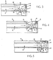
- Figure 3 is a side elevational view showing the magnetic recorder housing access door closed by operation of the invention mechanism and a tape cassette approaching the door from within the recorder housing under the influence of the automated unloader.
- Figure 4 is a side elevational view showing the door half-opened as a result of engagement of the invention mechanism by the approaching tape cassette being unloaded.
- Figure 5 is a side elevational view showing the door fully opened under the influence of the invention mechanism so that the tape cassette being unloaded can proceed out of the recorder housing.
- the door 1 is mounted for rotation about a hinge shaft 2 disposed at the top of the door and extending laterally across the outward face wall O of the recorder housing R and parallel to the length of the door 1 and the length of the rectangular slot 2.
- the bottom end of the door is formed with an abutment member 3 which engages against a hard stop surface 4 formed in the frame of the recorder housing and also extending laterally along the outward face wall the length of the slot.
- the presence of the hard stop 4 prevents the door 1 from rotating outward from the recorder housing, that is, in a clockwise direction beyond the plane of the recorder housing face wall, as viewed in Figure 3.
- the door 1 is shown in its closed position in Figures 2 and 3.
- a door opening mechanism 5 which is a specially configured fulcrum device.
- at least one mechanism 5 is positioned within the recorder housing adjacent one side edge of the door 1, although it will be appreciated that a pair of such mechanisms 5 could be utilized adjacent both side edges of the door 1.
- the mechanism 5 includes, preferably, a one-piece elongated member 6, which is preferably made of an integrally molded material, such as plastic.
- the member 6 has a generally linear arm 7 extending outward from the base portion of the member 6 to a free end.
- the base portion of the member 6 is journaled on a pivot shaft 8, having a longitudinal axis parallel with the longitudinal axis of the hinge shaft 2.
- the base 8 of the member 6 and the outwardly extending arm 7 occupies space off to one side of a track plate 9 over which tape cassettes pass during their insertion and ejection in the recorder housing.
- extending inward from the base of the member 6 is an upwardly curved cam surface 10 of a lateral thickness, as shown in Figure 2, which causes it to extend across the longitudinal travel path of a tape cassette passing over the track plate 9 during loading and unloading.
- the upward extension of the curve configuration of the cam surface 10 breaks across the horizontal planes of the tape cassette during loading and unloading, such that the bottom surface or base plate of the tape cassette engages the upper regions of the curved cam surface 10 during loading and unloading.
- the member 6 is disposed for rotation about the pivot shaft 8; however, a spring force is applied in the mechanism 5 to resist the rotation of the member 6 in the counter clockwise direction as shown in Figure 1 and actually to bias the member 6 in the clockwise direction.
- this spring force is applied to the member 6 by an integrally molded spring leg 11, which is fixed at one end to the housing frame track plate 9 and connected at its other end to the base of the member 6, as shown in Figure 1.
- the door 1 is normally held closed by the mechanism 5.
- the pin 12 also has its longitudinal axis parallel to the longitudinal axis of the door hinge rod 2.
- the free end of the arm 7 and the side edge of the door 1 are rotatable about the longitudinal axis of the pin 12.
- Between the arm 7 and the side edge of the door 1 is a stationary wall 13 which is provided with an arc-shaped groove 14 in which the pin is fitted and through which the pin 12 extends in the direction of its longitudinal axis.
- the groove 14 defines a travel path for the free end of the arm 7 in rotation about the pivot shaft 8.
- the mechanism 5 is rotatable about the pivot shaft 8 the distance of the arc defined by the groove 14.
- the spring force acting on the member 6 is overcome and the door is swung open by the force of the operator pressing the inward facing, leading edge of the tape cassette C against the door 1.
- the door 1 continues to be held open by the lower surfaces of the door supported and riding over the top surface of the tape cassette.
- the cassette When the tape cassette is to be unloaded from the recorder housing, the cassette is engaged by an automated unloader mechanism which transports the loaded cassette C, as shown in Figure 3, longitudinally outward toward the track plate 9 and the closed door 1.
- the door 1 thus remains swung open during unloading of the cassette, even after the automated unloader mechanism has ceased forced ejection of the cassette from the recorder housing, until the operator manually withdraws the cassette fully from the recorder housing.
Landscapes
- Casings For Electric Apparatus (AREA)
Applications Claiming Priority (2)
| Application Number | Priority Date | Filing Date | Title |
|---|---|---|---|
| US88801 | 1987-08-24 | ||
| US08/088,801 US5430587A (en) | 1993-07-08 | 1993-07-08 | Cassette-activated mechanism for inwardly opening recorder door |
Publications (3)
| Publication Number | Publication Date |
|---|---|
| EP0633569A2 true EP0633569A2 (fr) | 1995-01-11 |
| EP0633569A3 EP0633569A3 (fr) | 1995-07-19 |
| EP0633569B1 EP0633569B1 (fr) | 1998-02-04 |
Family
ID=22213565
Family Applications (1)
| Application Number | Title | Priority Date | Filing Date |
|---|---|---|---|
| EP93118136A Expired - Lifetime EP0633569B1 (fr) | 1993-07-08 | 1993-11-09 | Mécanisme d'ouverture de porte pour l'éjection d'une cassette à bande magnétique |
Country Status (4)
| Country | Link |
|---|---|
| US (1) | US5430587A (fr) |
| EP (1) | EP0633569B1 (fr) |
| JP (1) | JP2633806B2 (fr) |
| DE (1) | DE69316886T2 (fr) |
Cited By (1)
| Publication number | Priority date | Publication date | Assignee | Title |
|---|---|---|---|---|
| EP0779615A3 (fr) * | 1995-12-15 | 1998-08-05 | Sharp Kabushiki Kaisha | Appareil d'enregistrement et de reproduction avec un mécanisme pour ouvrir et fermer une enveloppe |
Families Citing this family (7)
| Publication number | Priority date | Publication date | Assignee | Title |
|---|---|---|---|---|
| JPH06223471A (ja) * | 1993-01-29 | 1994-08-12 | Sony Corp | ディスク記録及び/又は再生装置 |
| US5886848A (en) * | 1993-09-16 | 1999-03-23 | Daewoo Electronics Co., Ltd. | Cassette loading device for use in a video cassette recorder |
| KR100238263B1 (ko) * | 1995-11-02 | 2000-01-15 | 윤종용 | 테이프레코더의테이프카세트로딩장치 |
| KR0170305B1 (ko) * | 1995-11-08 | 1999-04-15 | 김광호 | 테이프 레코더의 프론트 도어 잠금장치 |
| US5909335A (en) * | 1997-01-17 | 1999-06-01 | Tandberg Data Asa | Tape drive start up and stop tape speed control |
| US6111725A (en) * | 1997-10-31 | 2000-08-29 | Tandberg Data Asa | Tape cartridge having a retractable door |
| US6581865B1 (en) * | 2002-01-18 | 2003-06-24 | Quantum Corporation | Retracting door assembly |
Family Cites Families (20)
| Publication number | Priority date | Publication date | Assignee | Title |
|---|---|---|---|---|
| US3976262A (en) * | 1973-12-17 | 1976-08-24 | C. J. Kennedy Company | Magnetic tape cartridge recorder having releasable cartridge catch arrangement and non-resonant type drive |
| JPS5894158A (ja) * | 1981-11-28 | 1983-06-04 | Tamura Electric Works Ltd | テ−プ収納筐体の誤插入防止装置 |
| US4573091A (en) * | 1982-11-15 | 1986-02-25 | Cipher Data Products, Inc. | Cartridge tape drive |
| DE3317720A1 (de) * | 1982-11-29 | 1984-11-22 | Tandberg Data A/S, Oslo | Magnetbandgeraet |
| JPS60647A (ja) * | 1983-06-15 | 1985-01-05 | Hitachi Ltd | カセツト装着装置 |
| JPS60120593U (ja) * | 1984-01-23 | 1985-08-14 | シャープ株式会社 | カセツト装填装置の蓋の開閉機構 |
| JPH0356901Y2 (fr) * | 1985-01-29 | 1991-12-24 | ||
| JPS61208661A (ja) * | 1985-03-13 | 1986-09-17 | Sanyo Electric Co Ltd | カセツトロ−デイング機構 |
| JPS62295291A (ja) * | 1986-06-14 | 1987-12-22 | Alps Electric Co Ltd | ドア装置 |
| JPS6344392A (ja) * | 1986-08-12 | 1988-02-25 | Clarion Co Ltd | 防塵ドア機構 |
| JPH01116953A (ja) * | 1987-10-30 | 1989-05-09 | Toshiba Corp | フロントローディング装置 |
| JPH0734516Y2 (ja) * | 1987-12-25 | 1995-08-02 | アルパイン株式会社 | カセットプレーヤ |
| JPH07114051B2 (ja) * | 1988-06-24 | 1995-12-06 | シャープ株式会社 | 磁気記録再生装置のカセット装填機構 |
| JPH0231362A (ja) * | 1988-07-20 | 1990-02-01 | Fujitsu General Ltd | フロントローディング装置の扉開閉機構 |
| JPH0258755A (ja) * | 1988-08-24 | 1990-02-27 | Hitachi Ltd | カセット装着装置 |
| JP2727657B2 (ja) * | 1989-05-31 | 1998-03-11 | ソニー株式会社 | カセット装着装置 |
| DE4025155A1 (de) * | 1989-11-09 | 1991-05-16 | Wangtek | Bandkassetten-antrieb |
| US5204792A (en) * | 1989-11-09 | 1993-04-20 | Wangtek, Inc. | Cartridge tape drive |
| JPH04355250A (ja) * | 1991-06-03 | 1992-12-09 | Matsushita Electric Ind Co Ltd | 磁気記録再生装置 |
| DE4129945A1 (de) * | 1991-09-09 | 1993-03-11 | Philips Patentverwaltung | Schwenkvorrichtung fuer eine abdeckklappe am kassettenschacht eines magnetbandkassettengeraetes |
-
1993
- 1993-07-08 US US08/088,801 patent/US5430587A/en not_active Expired - Fee Related
- 1993-11-09 EP EP93118136A patent/EP0633569B1/fr not_active Expired - Lifetime
- 1993-11-09 DE DE69316886T patent/DE69316886T2/de not_active Expired - Fee Related
-
1994
- 1994-04-07 JP JP6069742A patent/JP2633806B2/ja not_active Expired - Lifetime
Cited By (2)
| Publication number | Priority date | Publication date | Assignee | Title |
|---|---|---|---|---|
| EP0779615A3 (fr) * | 1995-12-15 | 1998-08-05 | Sharp Kabushiki Kaisha | Appareil d'enregistrement et de reproduction avec un mécanisme pour ouvrir et fermer une enveloppe |
| US6122140A (en) * | 1995-12-15 | 2000-09-19 | Sharp Kabushiki Kaisha | Cover opening and closing mechanism of a recording and reproducing apparatus |
Also Published As
| Publication number | Publication date |
|---|---|
| JP2633806B2 (ja) | 1997-07-23 |
| DE69316886T2 (de) | 1998-05-28 |
| EP0633569B1 (fr) | 1998-02-04 |
| EP0633569A3 (fr) | 1995-07-19 |
| DE69316886D1 (de) | 1998-03-12 |
| JPH0798972A (ja) | 1995-04-11 |
| US5430587A (en) | 1995-07-04 |
Similar Documents
| Publication | Publication Date | Title |
|---|---|---|
| US4785365A (en) | Door assembly with inner shutter for closing opening for cartridge insertion in disk drive device | |
| EP0170434B1 (fr) | Dispositif d'entraînement de bande en cassette | |
| US4866552A (en) | Magnetic tape drive with improved cartridge insertion and withdrawal mechanism | |
| US4694360A (en) | Tape cassette with concave engagement portion and player with hook engageable therewith | |
| US5430587A (en) | Cassette-activated mechanism for inwardly opening recorder door | |
| US4636890A (en) | Magnetic tape recorder | |
| US4755900A (en) | Tape cartridge drive with tape biasing arm to allow head movement normal to tape path | |
| US6666397B2 (en) | Tape cassette and cassette holder | |
| JP3024481B2 (ja) | ディスク装置 | |
| EP0563433A2 (fr) | Mécanisme de fermeture et de positionnement pour cartouche à bande | |
| JPS5992466A (ja) | 記録又は再生装置 | |
| KR0115137Y1 (ko) | 테이프 레코더의 프론트 도어 록킹장치 | |
| KR0113202Y1 (ko) | 자기기록재생기의 카세트 삽입 안전장치 | |
| JPH0210607Y2 (fr) | ||
| NL192410C (nl) | Cassettehouder voor buigzame schijf. | |
| JPS5819732Y2 (ja) | 磁気記録再生機のカセット収納装置 | |
| KR900007835Y1 (ko) | Vhd 디스크 케이스 | |
| KR970007172B1 (ko) | 자기기록재생기의 프론트 로딩용 하우징의 오삽입 방지장치 | |
| JPS6334148Y2 (fr) | ||
| JPH0690832B2 (ja) | テ−プカセツト装填装置 | |
| JPH0473227B2 (fr) | ||
| JPS62219360A (ja) | カセツトロ−デイング装置 | |
| JPS62248158A (ja) | カセツトテ−プの装着装置 | |
| JPH0731396Y2 (ja) | カセツトの二重挿入防止装置 | |
| KR930001254Y1 (ko) | V.t.r의 프론트 로딩 도어 개폐장치 |
Legal Events
| Date | Code | Title | Description |
|---|---|---|---|
| PUAI | Public reference made under article 153(3) epc to a published international application that has entered the european phase |
Free format text: ORIGINAL CODE: 0009012 |
|
| AK | Designated contracting states |
Kind code of ref document: A2 Designated state(s): DE FR GB |
|
| PUAL | Search report despatched |
Free format text: ORIGINAL CODE: 0009013 |
|
| AK | Designated contracting states |
Kind code of ref document: A3 Designated state(s): DE FR GB |
|
| 17P | Request for examination filed |
Effective date: 19951222 |
|
| 17Q | First examination report despatched |
Effective date: 19960216 |
|
| GRAG | Despatch of communication of intention to grant |
Free format text: ORIGINAL CODE: EPIDOS AGRA |
|
| GRAG | Despatch of communication of intention to grant |
Free format text: ORIGINAL CODE: EPIDOS AGRA |
|
| GRAH | Despatch of communication of intention to grant a patent |
Free format text: ORIGINAL CODE: EPIDOS IGRA |
|
| GRAH | Despatch of communication of intention to grant a patent |
Free format text: ORIGINAL CODE: EPIDOS IGRA |
|
| GRAA | (expected) grant |
Free format text: ORIGINAL CODE: 0009210 |
|
| AK | Designated contracting states |
Kind code of ref document: B1 Designated state(s): DE FR GB |
|
| PG25 | Lapsed in a contracting state [announced via postgrant information from national office to epo] |
Ref country code: FR Free format text: LAPSE BECAUSE OF FAILURE TO SUBMIT A TRANSLATION OF THE DESCRIPTION OR TO PAY THE FEE WITHIN THE PRESCRIBED TIME-LIMIT Effective date: 19980204 |
|
| REF | Corresponds to: |
Ref document number: 69316886 Country of ref document: DE Date of ref document: 19980312 |
|
| RAP2 | Party data changed (patent owner data changed or rights of a patent transferred) |
Owner name: TANDBERG DATA ASA |
|
| EN | Fr: translation not filed | ||
| PLBE | No opposition filed within time limit |
Free format text: ORIGINAL CODE: 0009261 |
|
| STAA | Information on the status of an ep patent application or granted ep patent |
Free format text: STATUS: NO OPPOSITION FILED WITHIN TIME LIMIT |
|
| 26N | No opposition filed | ||
| PGFP | Annual fee paid to national office [announced via postgrant information from national office to epo] |
Ref country code: FR Payment date: 19990525 Year of fee payment: 6 |
|
| PGFP | Annual fee paid to national office [announced via postgrant information from national office to epo] |
Ref country code: GB Payment date: 20000405 Year of fee payment: 7 |
|
| PG25 | Lapsed in a contracting state [announced via postgrant information from national office to epo] |
Ref country code: GB Free format text: LAPSE BECAUSE OF NON-PAYMENT OF DUE FEES Effective date: 20001109 |
|
| GBPC | Gb: european patent ceased through non-payment of renewal fee |
Effective date: 20001109 |
|
| PGFP | Annual fee paid to national office [announced via postgrant information from national office to epo] |
Ref country code: DE Payment date: 20011127 Year of fee payment: 9 |
|
| PG25 | Lapsed in a contracting state [announced via postgrant information from national office to epo] |
Ref country code: DE Free format text: LAPSE BECAUSE OF NON-PAYMENT OF DUE FEES Effective date: 20030603 |