EP0634755A2 - Câble électrique avec écran amélioré - Google Patents
Câble électrique avec écran amélioré Download PDFInfo
- Publication number
- EP0634755A2 EP0634755A2 EP94303610A EP94303610A EP0634755A2 EP 0634755 A2 EP0634755 A2 EP 0634755A2 EP 94303610 A EP94303610 A EP 94303610A EP 94303610 A EP94303610 A EP 94303610A EP 0634755 A2 EP0634755 A2 EP 0634755A2
- Authority
- EP
- European Patent Office
- Prior art keywords
- cable
- wrap
- shielding
- drain wire
- insulated
- Prior art date
- Legal status (The legal status is an assumption and is not a legal conclusion. Google has not performed a legal analysis and makes no representation as to the accuracy of the status listed.)
- Granted
Links
- 239000004020 conductor Substances 0.000 claims abstract description 50
- 230000005540 biological transmission Effects 0.000 abstract description 5
- 230000001934 delay Effects 0.000 description 2
- 239000011888 foil Substances 0.000 description 2
- 230000002411 adverse Effects 0.000 description 1
- XAGFODPZIPBFFR-UHFFFAOYSA-N aluminium Chemical compound [Al] XAGFODPZIPBFFR-UHFFFAOYSA-N 0.000 description 1
- 229910052782 aluminium Inorganic materials 0.000 description 1
- 239000012876 carrier material Substances 0.000 description 1
- 239000002131 composite material Substances 0.000 description 1
- 230000008878 coupling Effects 0.000 description 1
- 238000010168 coupling process Methods 0.000 description 1
- 238000005859 coupling reaction Methods 0.000 description 1
- 230000000694 effects Effects 0.000 description 1
- 238000009434 installation Methods 0.000 description 1
- 238000009413 insulation Methods 0.000 description 1
- 238000002955 isolation Methods 0.000 description 1
- 239000000463 material Substances 0.000 description 1
- 239000012811 non-conductive material Substances 0.000 description 1
- 229920000728 polyester Polymers 0.000 description 1
- 230000008054 signal transmission Effects 0.000 description 1
Images

Classifications
-
- H—ELECTRICITY
- H01—ELECTRIC ELEMENTS
- H01B—CABLES; CONDUCTORS; INSULATORS; SELECTION OF MATERIALS FOR THEIR CONDUCTIVE, INSULATING OR DIELECTRIC PROPERTIES
- H01B11/00—Communication cables or conductors
- H01B11/02—Cables with twisted pairs or quads
- H01B11/06—Cables with twisted pairs or quads with means for reducing effects of electromagnetic or electrostatic disturbances, e.g. screens
- H01B11/10—Screens specially adapted for reducing interference from external sources
- H01B11/1016—Screens specially adapted for reducing interference from external sources composed of a longitudinal lapped tape-conductor
-
- H—ELECTRICITY
- H01—ELECTRIC ELEMENTS
- H01B—CABLES; CONDUCTORS; INSULATORS; SELECTION OF MATERIALS FOR THEIR CONDUCTIVE, INSULATING OR DIELECTRIC PROPERTIES
- H01B11/00—Communication cables or conductors
- H01B11/02—Cables with twisted pairs or quads
- H01B11/06—Cables with twisted pairs or quads with means for reducing effects of electromagnetic or electrostatic disturbances, e.g. screens
Definitions
- the present invention relates to an electrical cable having at least two insulated signal conductors and one drain wire in contact with a layer of shielding that is wrapped around the signal conductors along the length of the cable.
- Modern signal transmission cables typically are shielded by a thin conductive foil and include a drain wire in contact therewith, running the length of the cable, that is used to terminate the foil shield.
- a transmission cable is shown in Figure 1 at 10.
- the cable 10 includes a pair of insulated signal conductors 12 and 14 and a non-insulated drain wire 16 all of which are arranged side by side as shown.
- a layer of conductive shielding material 18 is wrapped around the three conductor assembly so that it is in electrical contact with the non-insulated drain wire. This shielding prevents emissions from the cable as well as provides isolation from nearby or stray signals, and the planar structure of the cable provides advantages in routing and other cable management tasks for certain applications.
- a shielded electrical cable includes two insulated conductors, an uninsulated conductor, and a conductive shielding layer engaging the uninsulated conductor along its length.
- the shielding layer completely wraps both of the insulated conductors with a full wrap. Both insulated conductors are side by side within the full wrap, and the full wrap separates the uninsulated conductor from the insulated conductors.
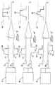
- FIG. 2 a schematic representation of propagation delay for the pair of insulated conductors 12 and 14 of Figure 1, showing, what is known in the industry as "delay skew". Following is a brief discussion of one of the causes of delay skew as it applies to the present invention.
- a signal is impressed on both signal conductors at the input end 30 of the cable and is shown as a single pulse 32 on each. Note that in differential mode these two pulses would be 180 degrees out of phase, however, for added clarity they are shown in phase.
- the pulses When the signal reaches the output end 34 of the cable, the pulses have shifted to the right, as viewed in Figure 2, an amount equal to the propagation delay for that particular cable type and length. These shifted pulses are identified as 36 and 38.
- the propagation delay for the conductor 14 is tD2 while the delay for the conductor 12 is a lesser amount tD1 caused by the air gaps 20.
- the delay skew as known in the industry, is defined as being equal to the absolute value tD2-tD1.
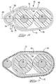
- FIG. 6 a cable 60 is shown having first and second insulated signal conductors 62 and 64 respectively and a drain wire 66, arranged so that their axes fall on a common plane 68.
- a layer 70 of shielding is wrapped completely around the two insulated conductors 62 and 64 for at least one full wrap 72, then an additional amount is wrapped about the drain wire 66 as at least a partial wrap 74 and terminated against the full wrap 72 so that the drain wire is sandwiched between the wrap 72 and the wrap 74.
- the layer 70 of shielding is a composite of two layers, a layer 80 of non-conductive material such as polyester or some other suitable carrier material and a layer 82 of aluminum or other suitable electrically conductive material deposited on the carrier, or otherwise attached thereto.
- a typical delay skew for the cable of Figure 6 is about 5 picoseconds per foot, resulting in a 0.5 nanosecond delay skew for a cable that is 100 feet long. This is well within the acceptable working range for a 500 megahertz application.
- the wrap 72 may be multiple wraps around the two insulated conductors and the partial wrap 74 may be a full wrap around the entire assembly or it may be multiple wraps therearound.
- the only requirement is that the drain wire 66 be disposed between any two adjacent wraps and in electrical engagement with the layer 82 of one of them.
- the non-insulated drain wire 66 is in electrical engagement with the conductive layer 82 of the wrap 74.
- the drain wire 66 is shown with its axis on the plane 68, it need not be so, provided that a flat cable profile is not desired nor needed.
- the conductive layer 82 and the non-conductive layer 80 may be reversed so that the conductive layer is facing outwardly from the wrap 72 so that the drain wire 66 is in electrical engagement therewith instead of with the conductive layer of the wrap 74.
- An alternative embodiment as shown in Figure 7, utilizes this reversed layer 70 which is wrapped only around the two insulated signal conductors 62 and 64.
- the non-insulated drain wire 66 is held in electrical engagement with the conductive layer 82 by means of an outer jacket 90.
- An important advantage of the present invention is that, in a differential pair cable, significant signal skew is reduced to a negligible amount or completely eliminated while maintaining the drain wire in the same plane as the two signal conductors for ease of cable management. Additionally, by placing the drain wire in the same plane with the signal conductors, it is easier to find and terminate by automated equipment.
Landscapes
- Physics & Mathematics (AREA)
- Electromagnetism (AREA)
- Communication Cables (AREA)
- Insulated Conductors (AREA)
Applications Claiming Priority (2)
| Application Number | Priority Date | Filing Date | Title |
|---|---|---|---|
| US08/091,577 US5416268A (en) | 1993-07-14 | 1993-07-14 | Electrical cable with improved shield |
| US91577 | 1993-07-14 |
Publications (3)
| Publication Number | Publication Date |
|---|---|
| EP0634755A2 true EP0634755A2 (fr) | 1995-01-18 |
| EP0634755A3 EP0634755A3 (fr) | 1996-06-05 |
| EP0634755B1 EP0634755B1 (fr) | 1999-12-01 |
Family
ID=22228508
Family Applications (1)
| Application Number | Title | Priority Date | Filing Date |
|---|---|---|---|
| EP94303610A Expired - Lifetime EP0634755B1 (fr) | 1993-07-14 | 1994-05-20 | Câble électrique avec écran amélioré |
Country Status (6)
| Country | Link |
|---|---|
| US (1) | US5416268A (fr) |
| EP (1) | EP0634755B1 (fr) |
| JP (1) | JP3659667B2 (fr) |
| KR (1) | KR100344867B1 (fr) |
| CN (1) | CN1101050C (fr) |
| DE (1) | DE69421853T2 (fr) |
Cited By (5)
| Publication number | Priority date | Publication date | Assignee | Title |
|---|---|---|---|---|
| EP2711937A4 (fr) * | 2011-05-19 | 2014-11-05 | Yazaki Corp | Câble de garde |
| EP2779176A3 (fr) * | 2013-03-14 | 2015-01-21 | Delphi Technologies, Inc. | Ensemble câble blindé |
| EP2884500A1 (fr) * | 2013-12-10 | 2015-06-17 | Delphi Technologies, Inc. | Ensemble câble blindé |
| US20180301247A1 (en) * | 2017-04-12 | 2018-10-18 | Sumitomo Electric Industries, Ltd. | Parallel pair cable |
| GB2524286B (en) * | 2014-03-19 | 2020-09-23 | Glanfield Anthony | Leak detection apparatus and methods |
Families Citing this family (52)
| Publication number | Priority date | Publication date | Assignee | Title |
|---|---|---|---|---|
| US5387113A (en) * | 1992-09-24 | 1995-02-07 | Woven Electronics Corp. | Composite shield jacket for electrical transmission cable |
| US5554825A (en) * | 1994-11-14 | 1996-09-10 | The Whitaker Corporation | Flexible cable with a shield and a ground conductor |
| US5556300A (en) * | 1994-11-14 | 1996-09-17 | The Whitaker Corporation | End connection for a flexible shielded cable conductor |
| US6486395B1 (en) * | 2000-06-22 | 2002-11-26 | Alflex Corporation | Interlocked metal-clad cable |
| US6504379B1 (en) * | 2000-11-16 | 2003-01-07 | Fluke Networks, Inc. | Cable assembly |
| JP2002289047A (ja) * | 2001-03-23 | 2002-10-04 | Sumitomo Electric Ind Ltd | 平行2心シールド電線とその製造方法 |
| US6444902B1 (en) * | 2001-04-10 | 2002-09-03 | Hon Hai Precision Ind. Co., Ltd. | Electrical cable |
| JP4021157B2 (ja) * | 2001-04-25 | 2007-12-12 | 矢崎総業株式会社 | 多芯シールド電線のシールド処理方法 |
| DE10152166C2 (de) * | 2001-10-23 | 2003-11-06 | Harman Becker Automotive Sys | Elektrische Leitung |
| US6630624B2 (en) * | 2001-11-08 | 2003-10-07 | Hon Hai Precision Ind. Co., Ltd. | Electrical cable with grounding means |
| JP4044766B2 (ja) * | 2002-02-04 | 2008-02-06 | 株式会社オートネットワーク技術研究所 | フラットシールドケーブル |
| CN1220218C (zh) * | 2002-07-18 | 2005-09-21 | 东莞蔻玛电子有限公司 | 高频传输缆线构造 |
| TWI246236B (en) * | 2002-07-22 | 2005-12-21 | Rapid Conn Inc | Electronic connector for a cable |
| TW590316U (en) * | 2003-03-05 | 2004-06-01 | Je-Jia Jang | Structure for transmission cable |
| JP4015061B2 (ja) * | 2003-05-27 | 2007-11-28 | 矢崎総業株式会社 | ワイヤーハーネス |
| JP2006190662A (ja) * | 2004-12-10 | 2006-07-20 | Hitachi Cable Ltd | 配線材およびその製造方法、並びにその製造に用いる抵抗溶接機 |
| US7623329B2 (en) * | 2005-01-04 | 2009-11-24 | Technology Research Corporation | Leakage current detection and interruption circuit with improved shield |
| US7423854B2 (en) * | 2006-07-07 | 2008-09-09 | Technology Research Corporation | Interruption circuit with improved shield |
| US20080041610A1 (en) * | 2006-08-15 | 2008-02-21 | Chih-Fang Cheng | Conducting cord that can resist static electricity and electromagnetic waves |
| TWM324838U (en) * | 2006-09-29 | 2008-01-01 | Transpower Technology Co Ltd | Transmission cable |
| US7754969B2 (en) | 2007-06-08 | 2010-07-13 | Southwire Company | Armored cable with integral support |
| TW200908025A (en) | 2007-06-27 | 2009-02-16 | Sumitomo Electric Industries | High-speed differential transmission cable |
| MX2010010957A (es) * | 2008-04-07 | 2011-02-23 | Wpfy Inc | Ensamble de cable forrado de metal. |
| WO2009126619A1 (fr) | 2008-04-08 | 2009-10-15 | Wpfy, Inc. | Câble à gainage métallique |
| US7827678B2 (en) * | 2008-06-12 | 2010-11-09 | General Cable Technologies Corp. | Longitudinal shield tape wrap applicator with edge folder to enclose drain wire |
| US7880089B1 (en) | 2008-06-13 | 2011-02-01 | Southwire Company | Metal-clad cable assembly |
| JP5508614B2 (ja) * | 2009-03-13 | 2014-06-04 | 株式会社潤工社 | 高速差動ケーブル |
| US7999185B2 (en) * | 2009-05-19 | 2011-08-16 | International Business Machines Corporation | Transmission cable with spirally wrapped shielding |
| WO2010148161A1 (fr) | 2009-06-19 | 2010-12-23 | 3M Innovative Properties Company | Câble électrique blindé |
| JP2011014391A (ja) * | 2009-07-02 | 2011-01-20 | Yazaki Corp | 金属箔巻きシールド電線 |
| US10141086B2 (en) * | 2009-12-01 | 2018-11-27 | Lenovo Enterprise Solutions (Singapore) Pte. Ltd. | Cable for high speed data communications |
| JP2011187323A (ja) * | 2010-03-09 | 2011-09-22 | Hitachi Cable Fine Tech Ltd | 極細シールドケーブル及びこれを用いたハーネス |
| JP2011204503A (ja) * | 2010-03-26 | 2011-10-13 | Hitachi Cable Fine Tech Ltd | フレキシブルフラットケーブル |
| US8552291B2 (en) * | 2010-05-25 | 2013-10-08 | International Business Machines Corporation | Cable for high speed data communications |
| US10325696B2 (en) * | 2010-06-02 | 2019-06-18 | Southwire Company, Llc | Flexible cable with structurally enhanced conductors |
| US8981216B2 (en) * | 2010-06-23 | 2015-03-17 | Tyco Electronics Corporation | Cable assembly for communicating signals over multiple conductors |
| EP2522021B1 (fr) | 2010-08-31 | 2016-07-27 | 3M Innovative Properties Company | Câble électrique blindé à haute densité et autres câbles blindés, systèmes et procédés |
| US10147522B2 (en) | 2010-08-31 | 2018-12-04 | 3M Innovative Properties Company | Electrical characteristics of shielded electrical cables |
| CN102870171B (zh) | 2010-08-31 | 2016-10-26 | 3M创新有限公司 | 屏蔽电缆 |
| JP5881677B2 (ja) * | 2010-08-31 | 2016-03-09 | スリーエム イノベイティブ プロパティズ カンパニー | 遮蔽電気ケーブルに関するコネクタ配置 |
| JP5755324B2 (ja) | 2010-08-31 | 2015-07-29 | スリーエム イノベイティブ プロパティズ カンパニー | 遮蔽電気ケーブルの電気的特性 |
| US12205732B2 (en) | 2010-08-31 | 2025-01-21 | 3M Innovative Properties Company | Shielded electric cable |
| JP2012138187A (ja) * | 2010-12-24 | 2012-07-19 | Sumitomo Wiring Syst Ltd | シールド電線及びシールド電線の製造方法 |
| CN102509574B (zh) * | 2011-11-04 | 2014-07-16 | 贸联电子(昆山)有限公司 | 高速差分对线结构 |
| US9472320B2 (en) | 2012-03-16 | 2016-10-18 | Wpfy, Inc. | Metal sheathed cable assembly with non-linear bonding/grounding conductor |
| JP5842722B2 (ja) * | 2012-04-20 | 2016-01-13 | 住友電装株式会社 | ワイヤーハーネス及びワイヤーハーネスの製造方法 |
| US20140262424A1 (en) * | 2013-03-14 | 2014-09-18 | Delphi Technologies, Inc. | Shielded twisted pair cable |
| JP5737323B2 (ja) * | 2013-05-01 | 2015-06-17 | 住友電気工業株式会社 | 電気絶縁ケーブル |
| CN104252915B (zh) * | 2013-06-28 | 2017-10-20 | 日立金属株式会社 | 差分信号传送用电缆 |
| US10079082B2 (en) * | 2015-07-30 | 2018-09-18 | Alltop Electronics (Suzhou) Ltd. | Data transmission cable |
| US10950367B1 (en) * | 2019-09-05 | 2021-03-16 | Te Connectivity Corporation | Electrical cable |
| US11342097B2 (en) * | 2020-08-03 | 2022-05-24 | Dell Products L.P. | Spiral shielding on a high speed cable |
Family Cites Families (12)
| Publication number | Priority date | Publication date | Assignee | Title |
|---|---|---|---|---|
| US3032604A (en) * | 1959-03-30 | 1962-05-01 | Belden Mfg Co | Electrical cable |
| US3673315A (en) * | 1970-09-08 | 1972-06-27 | Belden Corp | Shielded cable |
| US4041237A (en) * | 1974-08-19 | 1977-08-09 | Samuel Moore & Company | Electric conductor adapted for use in process instrumentation |
| US4098346A (en) * | 1976-10-01 | 1978-07-04 | Deere & Company | Steering for plow with adjustable plow bottoms |
| US4323721A (en) * | 1980-02-08 | 1982-04-06 | Belden Corporation | Electric cables with improved shielding member |
| US4327246A (en) * | 1980-02-19 | 1982-04-27 | Belden Corporation | Electric cables with improved shielding members |
| DE3011868A1 (de) * | 1980-03-27 | 1981-10-01 | Kabel- und Metallwerke Gutehoffnungshütte AG, 3000 Hannover | Feuchtigkeitsgeschuetztes elektrisches energiekabel |
| US4374299A (en) * | 1980-05-19 | 1983-02-15 | Belden Corporation | Triboelectric transducer cable |
| US4510346A (en) * | 1983-09-30 | 1985-04-09 | At&T Bell Laboratories | Shielded cable |
| CA1242006A (fr) * | 1985-12-16 | 1988-09-13 | Lawrence O'connor | Ruban de guipage de conducteurs electriques |
| US4800236A (en) * | 1986-08-04 | 1989-01-24 | E. I. Du Pont De Nemours And Company | Cable having a corrugated septum |
| GB8717954D0 (en) * | 1987-07-29 | 1987-09-03 | Kt Technologies Inc | Cable shielding tape |
-
1993
- 1993-07-14 US US08/091,577 patent/US5416268A/en not_active Expired - Lifetime
-
1994
- 1994-05-20 DE DE69421853T patent/DE69421853T2/de not_active Expired - Fee Related
- 1994-05-20 EP EP94303610A patent/EP0634755B1/fr not_active Expired - Lifetime
- 1994-07-07 KR KR1019940016331A patent/KR100344867B1/ko not_active Expired - Fee Related
- 1994-07-13 CN CN94108245A patent/CN1101050C/zh not_active Expired - Fee Related
- 1994-07-13 JP JP18384694A patent/JP3659667B2/ja not_active Expired - Fee Related
Cited By (7)
| Publication number | Priority date | Publication date | Assignee | Title |
|---|---|---|---|---|
| EP2711937A4 (fr) * | 2011-05-19 | 2014-11-05 | Yazaki Corp | Câble de garde |
| US9496071B2 (en) | 2011-05-19 | 2016-11-15 | Yazaki Corporation | Shield wire |
| EP2779176A3 (fr) * | 2013-03-14 | 2015-01-21 | Delphi Technologies, Inc. | Ensemble câble blindé |
| EP2884500A1 (fr) * | 2013-12-10 | 2015-06-17 | Delphi Technologies, Inc. | Ensemble câble blindé |
| GB2524286B (en) * | 2014-03-19 | 2020-09-23 | Glanfield Anthony | Leak detection apparatus and methods |
| US20180301247A1 (en) * | 2017-04-12 | 2018-10-18 | Sumitomo Electric Industries, Ltd. | Parallel pair cable |
| US10573434B2 (en) * | 2017-04-12 | 2020-02-25 | Sumitomo Electric Industries, Ltd. | Parallel pair cable |
Also Published As
| Publication number | Publication date |
|---|---|
| JP3659667B2 (ja) | 2005-06-15 |
| US5416268A (en) | 1995-05-16 |
| DE69421853D1 (de) | 2000-01-05 |
| CN1101050C (zh) | 2003-02-05 |
| CN1102501A (zh) | 1995-05-10 |
| JPH0757563A (ja) | 1995-03-03 |
| EP0634755B1 (fr) | 1999-12-01 |
| EP0634755A3 (fr) | 1996-06-05 |
| DE69421853T2 (de) | 2000-07-06 |
| KR960015605A (ko) | 1996-05-22 |
| KR100344867B1 (ko) | 2002-11-18 |
Similar Documents
| Publication | Publication Date | Title |
|---|---|---|
| US5416268A (en) | Electrical cable with improved shield | |
| US6010788A (en) | High speed data transmission cable and method of forming same | |
| US5329064A (en) | Superior shield cable | |
| KR101127252B1 (ko) | 불연속 케이블 차폐 시스템 및 방법 | |
| US4477693A (en) | Multiply shielded coaxial cable with very low transfer impedance | |
| US5673009A (en) | Connector for communication systems with cancelled crosstalk | |
| CA1160300A (fr) | Cable transducteur tribo-electrique | |
| US4287385A (en) | Shielded flat cable | |
| CA1166711A (fr) | Cables electriques a blindage isolant simple | |
| US4818820A (en) | Transmission system | |
| KR20020033052A (ko) | 전기 케이블 단부구조 및 전기 케이블 단부 처리방법 | |
| EP0109143B1 (fr) | Câbles téléphoniques blindés à plusieurs compartiments | |
| CN106463212A (zh) | 数据线缆 | |
| TWI806146B (zh) | 高速傳輸線纜與具有高速傳輸線纜的線端連接器 | |
| US3803340A (en) | "d."internal shield in telephone cables | |
| EP3544027B1 (fr) | Câble électrique | |
| EP1036427A1 (fr) | Procede de reduction d'un couplage de signaux haute frequence entre des paires de conducteurs dans un connecteur et connecteur de transfert de signaux differentiels | |
| JPS58148436A (ja) | 半導体装置 | |
| US10600536B1 (en) | Electrical cable | |
| EP3605562A1 (fr) | Câble de communication de données à paire torsadée avec paires individuellement blindées à l'aide d'un ruban de blindage discontinu | |
| US6971896B2 (en) | Flex strips for high frequency connectors | |
| EP3526802A1 (fr) | Câble à paire torsadée avec blindage flottant | |
| US10283238B1 (en) | Electrical cable | |
| ATE344971T1 (de) | Isolator für elektrische leiter mit aussenabschirmung. | |
| US10600537B1 (en) | Electrical cable |
Legal Events
| Date | Code | Title | Description |
|---|---|---|---|
| PUAI | Public reference made under article 153(3) epc to a published international application that has entered the european phase |
Free format text: ORIGINAL CODE: 0009012 |
|
| AK | Designated contracting states |
Kind code of ref document: A2 Designated state(s): DE FR GB |
|
| PUAL | Search report despatched |
Free format text: ORIGINAL CODE: 0009013 |
|
| AK | Designated contracting states |
Kind code of ref document: A3 Designated state(s): CH DE FR GB IT LI NL SE |
|
| 17P | Request for examination filed |
Effective date: 19960717 |
|
| 17Q | First examination report despatched |
Effective date: 19970409 |
|
| GRAG | Despatch of communication of intention to grant |
Free format text: ORIGINAL CODE: EPIDOS AGRA |
|
| GRAG | Despatch of communication of intention to grant |
Free format text: ORIGINAL CODE: EPIDOS AGRA |
|
| GRAG | Despatch of communication of intention to grant |
Free format text: ORIGINAL CODE: EPIDOS AGRA |
|
| GRAH | Despatch of communication of intention to grant a patent |
Free format text: ORIGINAL CODE: EPIDOS IGRA |
|
| GRAH | Despatch of communication of intention to grant a patent |
Free format text: ORIGINAL CODE: EPIDOS IGRA |
|
| RBV | Designated contracting states (corrected) |
Designated state(s): DE FR GB |
|
| GRAA | (expected) grant |
Free format text: ORIGINAL CODE: 0009210 |
|
| AK | Designated contracting states |
Kind code of ref document: B1 Designated state(s): DE FR GB |
|
| REF | Corresponds to: |
Ref document number: 69421853 Country of ref document: DE Date of ref document: 20000105 |
|
| ET | Fr: translation filed | ||
| PLBE | No opposition filed within time limit |
Free format text: ORIGINAL CODE: 0009261 |
|
| STAA | Information on the status of an ep patent application or granted ep patent |
Free format text: STATUS: NO OPPOSITION FILED WITHIN TIME LIMIT |
|
| 26N | No opposition filed | ||
| REG | Reference to a national code |
Ref country code: GB Ref legal event code: IF02 |
|
| PGFP | Annual fee paid to national office [announced via postgrant information from national office to epo] |
Ref country code: DE Payment date: 20080630 Year of fee payment: 15 |
|
| PGFP | Annual fee paid to national office [announced via postgrant information from national office to epo] |
Ref country code: GB Payment date: 20080529 Year of fee payment: 15 |
|
| GBPC | Gb: european patent ceased through non-payment of renewal fee |
Effective date: 20090520 |
|
| REG | Reference to a national code |
Ref country code: FR Ref legal event code: ST Effective date: 20100129 |
|
| PG25 | Lapsed in a contracting state [announced via postgrant information from national office to epo] |
Ref country code: FR Free format text: LAPSE BECAUSE OF NON-PAYMENT OF DUE FEES Effective date: 20090602 |
|
| PGFP | Annual fee paid to national office [announced via postgrant information from national office to epo] |
Ref country code: FR Payment date: 20080519 Year of fee payment: 15 |
|
| PG25 | Lapsed in a contracting state [announced via postgrant information from national office to epo] |
Ref country code: GB Free format text: LAPSE BECAUSE OF NON-PAYMENT OF DUE FEES Effective date: 20090520 |
|
| PG25 | Lapsed in a contracting state [announced via postgrant information from national office to epo] |
Ref country code: DE Free format text: LAPSE BECAUSE OF NON-PAYMENT OF DUE FEES Effective date: 20091201 |