EP0635607A1 - Construction de cheminée construite à plusieurs parties - Google Patents
Construction de cheminée construite à plusieurs parties Download PDFInfo
- Publication number
- EP0635607A1 EP0635607A1 EP94109079A EP94109079A EP0635607A1 EP 0635607 A1 EP0635607 A1 EP 0635607A1 EP 94109079 A EP94109079 A EP 94109079A EP 94109079 A EP94109079 A EP 94109079A EP 0635607 A1 EP0635607 A1 EP 0635607A1
- Authority
- EP
- European Patent Office
- Prior art keywords
- chimney system
- inner tube
- thread
- chimney
- cut
- Prior art date
- Legal status (The legal status is an assumption and is not a legal conclusion. Google has not performed a legal analysis and makes no representation as to the accuracy of the status listed.)
- Granted
Links
Images

Classifications
-
- F—MECHANICAL ENGINEERING; LIGHTING; HEATING; WEAPONS; BLASTING
- F23—COMBUSTION APPARATUS; COMBUSTION PROCESSES
- F23J—REMOVAL OR TREATMENT OF COMBUSTION PRODUCTS OR COMBUSTION RESIDUES; FLUES
- F23J13/00—Fittings for chimneys or flues
- F23J13/04—Joints; Connections
-
- E—FIXED CONSTRUCTIONS
- E04—BUILDING
- E04F—FINISHING WORK ON BUILDINGS, e.g. STAIRS, FLOORS
- E04F17/00—Vertical ducts; Channels, e.g. for drainage
- E04F17/02—Vertical ducts; Channels, e.g. for drainage for carrying away waste gases, e.g. flue gases; Building elements specially designed therefor, e.g. shaped bricks or sets thereof
-
- F—MECHANICAL ENGINEERING; LIGHTING; HEATING; WEAPONS; BLASTING
- F23—COMBUSTION APPARATUS; COMBUSTION PROCESSES
- F23J—REMOVAL OR TREATMENT OF COMBUSTION PRODUCTS OR COMBUSTION RESIDUES; FLUES
- F23J2213/00—Chimneys or flues
- F23J2213/20—Joints; Connections
- F23J2213/202—Joints; Connections between duct or stack sections
-
- F—MECHANICAL ENGINEERING; LIGHTING; HEATING; WEAPONS; BLASTING
- F23—COMBUSTION APPARATUS; COMBUSTION PROCESSES
- F23J—REMOVAL OR TREATMENT OF COMBUSTION PRODUCTS OR COMBUSTION RESIDUES; FLUES
- F23J2213/00—Chimneys or flues
- F23J2213/30—Specific materials
- F23J2213/304—Specific materials ceramic
Definitions
- the invention relates to a multi-part chimney system consisting of an outer shell, an inner tube and, if appropriate, an insulation layer inserted between the outer shell and the inner tube and each having a connection piece formed at the lower end of the upper inner tube and at the upper end of the subsequent lower inner tube.
- Multi-part chimney systems according to the type mentioned are known per se.
- the connecting pieces of the inner pipes of such chimney systems each have a tongue and a groove, so that the inner pipes lying one above the other can be joined together by the tongue and groove connection.
- an additional sealing compound is placed in the tongue and groove connection.
- Such chimney systems are suitable as vacuum chimneys, which are not mandatory have to be tight.
- multi-part chimney systems of the type mentioned are known, in which the connecting pieces of the inner pipes are also joined together by a tongue and groove connection and are connected by means of an outer steel sleeve with an inner rubber part or the like so that they are impervious and an escape of gases between the fittings is prevented.
- High pressure chimneys are generally suitable for temperatures below 100 ° C.
- the inner pipes or inner shell of multi-part chimney systems consist of individual ceramic pipes with different lengths and pipe inside diameters.
- the inner tubes are connected by tongue and groove.
- the seal between the respective tongue and groove is ensured during assembly by means of joint cement. Every joint connection therefore represents a weak point in the interior of the chimney, because the required acid and temperature resistance cannot be guaranteed with joint cement.
- the invention has for its object to provide a multi-part chimney system that can be used both as an overpressure chimney and as a vacuum chimney.
- each inner tube has at least one connector with an external thread.
- each lower connector has an internal thread and each upper connector of each inner tube has an external thread.
- each inner tube has both an upper and a lower connection piece with an external thread, such that two associated inner tubes can be connected at their connecting points by means of a sleeve.
- the internal thread is cut into a sleeve section, which in each case closes off the upper connecting piece of an inner tube.
- the inner pipes to be connected can be screwed together without the need to use joint cement or the like.
- the threads on an inner tube are introduced at one end outside and at the other end inside into the ceramic fragments.
- the individual inner tubes can then be screwed together by means of the thread, with no additional sealing material such as joint cement being required.
- a lubricant is used to facilitate screwing the inner tubes together.
- the entire inner chimney shell thus consists of only one material.
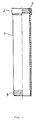
- an inner tube 1 consists of a ceramic body that is pressed and is in a wet state after running out of a press.
- the cullet or blank has a moisture content of about 17%, while after drying in a drying chamber the moisture content is reduced to 1% or less. After drying, the burning process usually takes place.
- the inner tube 1 is provided with a sleeve 2 formed on the upper connecting piece, into which an internal thread 4 with a predetermined pitch is cut either when wet or after the blank has been fired.
- An external thread 6 corresponding to the internal thread 4 is cut into the lower connecting piece of the tube 1, likewise either while the blank is still wet or also after the internal tube has burned.
- the number of threads of the lower connector 6 can be greater than the number of threads of the internal thread 4.
- the threads can be cut by pressing them in using a roller, or they can be ground in or screwed in using separate processing machines.
- FIG. 2 shows the lower connecting piece 14 with respect to the inner tube 10 and the upper connecting piece 16 with respect to the inner tube 11 located below it.
- the inner tubes 10, 11 are provided with a matching external thread 17, 18.
- the end edges of the inner tubes 10, 11 are straight and can maintain a gap with one another, which can be filled in by an annular seal, even if this is not shown in FIG. 2.
- the sum of the heights of the threads 17, 18, that is to say the sum of the thread heights of the assigned external threads, is preferably greater than the width or the height of the internal thread of the sleeve 19.
- the sleeve 19 can consist of the same material as the inner tube 10 or 11 or of plastic.
- FIG. 3 shows a detailed sectional view in the area of the sleeve 19 or in the connection area between two adjacent inner tubes.
- the end edges 22, 23, that is to say the lower end edge 22 of, for example, the inner tube 10 and the upper end edge of the inner tube 11 located underneath, are conical, as a result of which condensed water escapes, which runs down the inner walls of the tubes 10, 11. is prevented beyond the connecting surfaces 22,23.
- the use of an additional O-seal, as described in the embodiment according to FIG. 2, may be superfluous.
Landscapes
- Engineering & Computer Science (AREA)
- Architecture (AREA)
- Mechanical Engineering (AREA)
- General Engineering & Computer Science (AREA)
- Civil Engineering (AREA)
- Structural Engineering (AREA)
- Working Measures On Existing Buildindgs (AREA)
- Chimneys And Flues (AREA)
- Tents Or Canopies (AREA)
- Thermal Insulation (AREA)
- Rigid Pipes And Flexible Pipes (AREA)
Applications Claiming Priority (4)
| Application Number | Priority Date | Filing Date | Title |
|---|---|---|---|
| DE4324514 | 1993-07-21 | ||
| DE4324514 | 1993-07-21 | ||
| DE4337696A DE4337696C2 (de) | 1993-07-21 | 1993-11-04 | Mehrteilig aufgebaute Schornsteinanlage |
| DE4337696 | 1993-11-04 |
Publications (2)
| Publication Number | Publication Date |
|---|---|
| EP0635607A1 true EP0635607A1 (fr) | 1995-01-25 |
| EP0635607B1 EP0635607B1 (fr) | 1996-01-17 |
Family
ID=25927896
Family Applications (1)
| Application Number | Title | Priority Date | Filing Date |
|---|---|---|---|
| EP94109079A Expired - Lifetime EP0635607B1 (fr) | 1993-07-21 | 1994-06-14 | Construction de cheminée construite à plusieurs parties |
Country Status (6)
| Country | Link |
|---|---|
| EP (1) | EP0635607B1 (fr) |
| AT (1) | ATE133226T1 (fr) |
| CZ (1) | CZ161494A3 (fr) |
| DK (1) | DK0635607T3 (fr) |
| HU (1) | HUT72578A (fr) |
| SK (1) | SK79794A3 (fr) |
Cited By (1)
| Publication number | Priority date | Publication date | Assignee | Title |
|---|---|---|---|---|
| EP1054213A1 (fr) * | 1999-05-17 | 2000-11-22 | JACOB PLEIN-WAGNER SÖHNE STEINZEUGWARENFABRIK GmbH + Co. KG | Procédé pour la fabrication d'un tuyau intérieur de cheminée en céramique avec tenon et mortaise aux extrémités |
Citations (4)
| Publication number | Priority date | Publication date | Assignee | Title |
|---|---|---|---|---|
| US2766054A (en) * | 1952-09-29 | 1956-10-09 | Nat Clay Pipe Res Corp | Threaded joint-sealing gasket rings for molded pipe |
| FR1519824A (fr) * | 1967-02-17 | 1968-04-05 | Perfectionnements aux gaines de fumée et de ventilation | |
| DE8914427U1 (de) * | 1989-12-07 | 1990-03-29 | Didier-Werke Ag, 6200 Wiesbaden | Keramisches Rohr mit einer Anordnung zur lösbaren Verbindung mehrerer dieser Rohre |
| EP0522410A1 (fr) * | 1991-06-28 | 1993-01-13 | Schiedel GmbH & Co. | Train de tuyau pour l'éduction des gaz d'échappement dans une cheminée de maison necessitant une restauration, procédé de production et application du train de tuyau |
-
1994
- 1994-06-14 EP EP94109079A patent/EP0635607B1/fr not_active Expired - Lifetime
- 1994-06-14 DK DK94109079.7T patent/DK0635607T3/da active
- 1994-06-14 AT AT94109079T patent/ATE133226T1/de not_active IP Right Cessation
- 1994-07-01 SK SK797-94A patent/SK79794A3/sk unknown
- 1994-07-01 CZ CZ941614A patent/CZ161494A3/cs unknown
- 1994-07-20 HU HU9402144A patent/HUT72578A/hu unknown
Patent Citations (4)
| Publication number | Priority date | Publication date | Assignee | Title |
|---|---|---|---|---|
| US2766054A (en) * | 1952-09-29 | 1956-10-09 | Nat Clay Pipe Res Corp | Threaded joint-sealing gasket rings for molded pipe |
| FR1519824A (fr) * | 1967-02-17 | 1968-04-05 | Perfectionnements aux gaines de fumée et de ventilation | |
| DE8914427U1 (de) * | 1989-12-07 | 1990-03-29 | Didier-Werke Ag, 6200 Wiesbaden | Keramisches Rohr mit einer Anordnung zur lösbaren Verbindung mehrerer dieser Rohre |
| EP0522410A1 (fr) * | 1991-06-28 | 1993-01-13 | Schiedel GmbH & Co. | Train de tuyau pour l'éduction des gaz d'échappement dans une cheminée de maison necessitant une restauration, procédé de production et application du train de tuyau |
Cited By (1)
| Publication number | Priority date | Publication date | Assignee | Title |
|---|---|---|---|---|
| EP1054213A1 (fr) * | 1999-05-17 | 2000-11-22 | JACOB PLEIN-WAGNER SÖHNE STEINZEUGWARENFABRIK GmbH + Co. KG | Procédé pour la fabrication d'un tuyau intérieur de cheminée en céramique avec tenon et mortaise aux extrémités |
Also Published As
| Publication number | Publication date |
|---|---|
| SK79794A3 (en) | 1995-03-08 |
| HUT72578A (en) | 1996-05-28 |
| ATE133226T1 (de) | 1996-02-15 |
| HU9402144D0 (en) | 1994-10-28 |
| EP0635607B1 (fr) | 1996-01-17 |
| DK0635607T3 (da) | 1996-02-12 |
| CZ161494A3 (en) | 1995-02-15 |
Similar Documents
| Publication | Publication Date | Title |
|---|---|---|
| DE3431599C2 (de) | Anordnung zum Verbinden der Enden von Rohren oder rohrförmigen Verbindungsteilen | |
| DE3605020C2 (fr) | ||
| CH636938A5 (de) | Dichtungsring und verfahren fuer dessen herstellung. | |
| DE69002721T2 (de) | Rohrverbindung. | |
| DE2538808A1 (de) | Verbindungsrohrstueck mit o-ringen | |
| DE4000654C2 (fr) | ||
| DE2201306A1 (de) | Rohrkupplung | |
| EP0424617A2 (fr) | Conduit de fumée pour cheminée composée de plusieurs segments | |
| EP0635607B1 (fr) | Construction de cheminée construite à plusieurs parties | |
| DE4337696C2 (de) | Mehrteilig aufgebaute Schornsteinanlage | |
| DE19611580C1 (de) | Rohrabschnitt eines doppelwandigen Kaminrohrs für den Schornsteinbau | |
| DE4325349C2 (de) | Verbindungsvorrichtung | |
| DE3130922C1 (de) | Verschraubungssystem | |
| DE19800512C2 (de) | Muffensteckverbindung für Rohre, insbesondere Abgas- und Kaminrohre | |
| DE102023107561A1 (de) | Rohrverbinder mit Halteeinrichtung | |
| EP1043535A1 (fr) | Dispositif de raccordement d'éléments de tuyauterie | |
| DE19635053C2 (de) | Schlaucharmatur für Druckschläuche | |
| DE4401672A1 (de) | Rohrverbinder | |
| DE19547901A1 (de) | Schornsteinrohr aus keramischem Material | |
| DE2233102A1 (de) | Rohrverbindung sowie verfahren und verbindungshuelse zur herstellung der rohrverbindung | |
| EP0716259A1 (fr) | Assemblage de joints pour tuyaux, en particulier pour tuyaux de cheminée en céramique | |
| DE202013002004U1 (de) | Kaminrohr sowie Abgasanlage mit einem solchen Kaminrohr | |
| DE3136183A1 (de) | Dichtungsanordnung fuer eine muffenverbindung an rohren | |
| DE9310923U1 (de) | Mehrteilig aufgebaute Schornsteinanlage | |
| EP0505864A1 (fr) | Tige en matériau isolant |
Legal Events
| Date | Code | Title | Description |
|---|---|---|---|
| PUAI | Public reference made under article 153(3) epc to a published international application that has entered the european phase |
Free format text: ORIGINAL CODE: 0009012 |
|
| 17P | Request for examination filed |
Effective date: 19940803 |
|
| AK | Designated contracting states |
Kind code of ref document: A1 Designated state(s): AT BE CH DE DK FR IT LI LU NL |
|
| 17Q | First examination report despatched |
Effective date: 19950110 |
|
| RAP1 | Party data changed (applicant data changed or rights of an application transferred) |
Owner name: STEINZEUGWERK PONHOLZ GMBH & CO. KG |
|
| GRAA | (expected) grant |
Free format text: ORIGINAL CODE: 0009210 |
|
| AK | Designated contracting states |
Kind code of ref document: B1 Designated state(s): AT BE CH DE DK FR IT LI LU NL |
|
| REF | Corresponds to: |
Ref document number: 133226 Country of ref document: AT Date of ref document: 19960215 Kind code of ref document: T |
|
| REG | Reference to a national code |
Ref country code: DK Ref legal event code: T3 |
|
| REF | Corresponds to: |
Ref document number: 59400089 Country of ref document: DE Date of ref document: 19960229 |
|
| ITF | It: translation for a ep patent filed | ||
| ET | Fr: translation filed | ||
| REG | Reference to a national code |
Ref country code: CH Ref legal event code: NV Representative=s name: HEPP, WENGER & RYFFEL AG |
|
| PLBE | No opposition filed within time limit |
Free format text: ORIGINAL CODE: 0009261 |
|
| STAA | Information on the status of an ep patent application or granted ep patent |
Free format text: STATUS: NO OPPOSITION FILED WITHIN TIME LIMIT |
|
| 26N | No opposition filed | ||
| PGFP | Annual fee paid to national office [announced via postgrant information from national office to epo] |
Ref country code: FR Payment date: 19980609 Year of fee payment: 5 |
|
| PGFP | Annual fee paid to national office [announced via postgrant information from national office to epo] |
Ref country code: DK Payment date: 19980612 Year of fee payment: 5 |
|
| PGFP | Annual fee paid to national office [announced via postgrant information from national office to epo] |
Ref country code: AT Payment date: 19980615 Year of fee payment: 5 |
|
| PGFP | Annual fee paid to national office [announced via postgrant information from national office to epo] |
Ref country code: NL Payment date: 19980629 Year of fee payment: 5 Ref country code: LU Payment date: 19980629 Year of fee payment: 5 |
|
| PGFP | Annual fee paid to national office [announced via postgrant information from national office to epo] |
Ref country code: CH Payment date: 19980702 Year of fee payment: 5 |
|
| PGFP | Annual fee paid to national office [announced via postgrant information from national office to epo] |
Ref country code: BE Payment date: 19980813 Year of fee payment: 5 |
|
| PGFP | Annual fee paid to national office [announced via postgrant information from national office to epo] |
Ref country code: DE Payment date: 19980819 Year of fee payment: 5 |
|
| PG25 | Lapsed in a contracting state [announced via postgrant information from national office to epo] |
Ref country code: LU Free format text: LAPSE BECAUSE OF NON-PAYMENT OF DUE FEES Effective date: 19990614 Ref country code: AT Free format text: LAPSE BECAUSE OF NON-PAYMENT OF DUE FEES Effective date: 19990614 |
|
| PG25 | Lapsed in a contracting state [announced via postgrant information from national office to epo] |
Ref country code: LI Free format text: LAPSE BECAUSE OF NON-PAYMENT OF DUE FEES Effective date: 19990630 Ref country code: FR Free format text: THE PATENT HAS BEEN ANNULLED BY A DECISION OF A NATIONAL AUTHORITY Effective date: 19990630 Ref country code: DK Free format text: LAPSE BECAUSE OF NON-PAYMENT OF DUE FEES Effective date: 19990630 Ref country code: CH Free format text: LAPSE BECAUSE OF NON-PAYMENT OF DUE FEES Effective date: 19990630 Ref country code: BE Free format text: LAPSE BECAUSE OF NON-PAYMENT OF DUE FEES Effective date: 19990630 |
|
| BERE | Be: lapsed |
Owner name: STEINZEUGWERK PONHOLZ G.M.B.H. & CO. K.G. Effective date: 19990630 |
|
| PG25 | Lapsed in a contracting state [announced via postgrant information from national office to epo] |
Ref country code: NL Free format text: LAPSE BECAUSE OF NON-PAYMENT OF DUE FEES Effective date: 20000101 |
|
| REG | Reference to a national code |
Ref country code: CH Ref legal event code: PL |
|
| NLV4 | Nl: lapsed or anulled due to non-payment of the annual fee |
Effective date: 20000101 |
|
| REG | Reference to a national code |
Ref country code: DK Ref legal event code: EBP |
|
| PG25 | Lapsed in a contracting state [announced via postgrant information from national office to epo] |
Ref country code: DE Free format text: LAPSE BECAUSE OF NON-PAYMENT OF DUE FEES Effective date: 20000503 |
|
| REG | Reference to a national code |
Ref country code: FR Ref legal event code: ST |
|
| PG25 | Lapsed in a contracting state [announced via postgrant information from national office to epo] |
Ref country code: IT Free format text: LAPSE BECAUSE OF NON-PAYMENT OF DUE FEES Effective date: 20050614 |