EP0635703A1 - Détecteur de charge avec capteur de déplacement et dispositif de pesage l'utilisant - Google Patents
Détecteur de charge avec capteur de déplacement et dispositif de pesage l'utilisant Download PDFInfo
- Publication number
- EP0635703A1 EP0635703A1 EP94111446A EP94111446A EP0635703A1 EP 0635703 A1 EP0635703 A1 EP 0635703A1 EP 94111446 A EP94111446 A EP 94111446A EP 94111446 A EP94111446 A EP 94111446A EP 0635703 A1 EP0635703 A1 EP 0635703A1
- Authority
- EP
- European Patent Office
- Prior art keywords
- fixed
- displacement sensor
- weighing cell
- movable
- strain
- Prior art date
- Legal status (The legal status is an assumption and is not a legal conclusion. Google has not performed a legal analysis and makes no representation as to the accuracy of the status listed.)
- Granted
Links
- 238000006073 displacement reaction Methods 0.000 title claims abstract description 137
- 238000005303 weighing Methods 0.000 title claims abstract description 107
- 230000001939 inductive effect Effects 0.000 claims abstract description 49
- 239000002184 metal Substances 0.000 claims description 10
- 230000001105 regulatory effect Effects 0.000 claims description 8
- CIWBSHSKHKDKBQ-JLAZNSOCSA-N Ascorbic acid Chemical compound OC[C@H](O)[C@H]1OC(=O)C(O)=C1O CIWBSHSKHKDKBQ-JLAZNSOCSA-N 0.000 description 21
- 239000000463 material Substances 0.000 description 18
- 238000000034 method Methods 0.000 description 13
- 239000010410 layer Substances 0.000 description 11
- 238000005259 measurement Methods 0.000 description 7
- 239000010408 film Substances 0.000 description 6
- 238000003466 welding Methods 0.000 description 6
- 239000004020 conductor Substances 0.000 description 5
- 238000005530 etching Methods 0.000 description 5
- 238000012545 processing Methods 0.000 description 5
- 230000000873 masking effect Effects 0.000 description 4
- 229910001220 stainless steel Inorganic materials 0.000 description 4
- 239000010935 stainless steel Substances 0.000 description 4
- 239000010409 thin film Substances 0.000 description 4
- 230000015572 biosynthetic process Effects 0.000 description 3
- 230000002829 reductive effect Effects 0.000 description 3
- 230000002411 adverse Effects 0.000 description 2
- 238000010276 construction Methods 0.000 description 2
- -1 for example Substances 0.000 description 2
- 238000003780 insertion Methods 0.000 description 2
- 230000037431 insertion Effects 0.000 description 2
- 239000011159 matrix material Substances 0.000 description 2
- 238000012986 modification Methods 0.000 description 2
- 230000004048 modification Effects 0.000 description 2
- 238000005096 rolling process Methods 0.000 description 2
- 229910021417 amorphous silicon Inorganic materials 0.000 description 1
- 238000004364 calculation method Methods 0.000 description 1
- 238000005520 cutting process Methods 0.000 description 1
- 125000004122 cyclic group Chemical group 0.000 description 1
- 230000007423 decrease Effects 0.000 description 1
- 238000001514 detection method Methods 0.000 description 1
- 238000010586 diagram Methods 0.000 description 1
- 238000009434 installation Methods 0.000 description 1
- 230000000670 limiting effect Effects 0.000 description 1
- 238000004519 manufacturing process Methods 0.000 description 1
- 238000010297 mechanical methods and process Methods 0.000 description 1
- 230000005226 mechanical processes and functions Effects 0.000 description 1
- 239000011241 protective layer Substances 0.000 description 1
- 230000000717 retained effect Effects 0.000 description 1
- 238000007650 screen-printing Methods 0.000 description 1
- 239000004065 semiconductor Substances 0.000 description 1
- 230000035945 sensitivity Effects 0.000 description 1
- 238000004544 sputter deposition Methods 0.000 description 1
Images


Classifications
-
- G—PHYSICS
- G01—MEASURING; TESTING
- G01G—WEIGHING
- G01G23/00—Auxiliary devices for weighing apparatus
- G01G23/06—Means for damping oscillations, e.g. of weigh beams
- G01G23/10—Means for damping oscillations, e.g. of weigh beams by electric or magnetic means
-
- G—PHYSICS
- G01—MEASURING; TESTING
- G01G—WEIGHING
- G01G3/00—Weighing apparatus characterised by the use of elastically-deformable members, e.g. spring balances
- G01G3/12—Weighing apparatus characterised by the use of elastically-deformable members, e.g. spring balances wherein the weighing element is in the form of a solid body stressed by pressure or tension during weighing
- G01G3/14—Weighing apparatus characterised by the use of elastically-deformable members, e.g. spring balances wherein the weighing element is in the form of a solid body stressed by pressure or tension during weighing measuring variations of electrical resistance
- G01G3/1414—Arrangements for correcting or for compensating for unwanted effects
Definitions
- the present invention relates to a weighing cell suited particularly for use in association with a weight checker and/or a combinational weighing apparatus, which cell is equipped with a displacement sensor designed to detect a vibratory component such as, for example, floor vibration, and also to a weighing apparatus utilizing such weighing cell equipped with the displacement sensor.
- a so-called floor vibration that is, a low frequency vibration, harmful to a weighing cell (a load detector) is often generated at the site where there is installed a weighing apparatus such as, for example, a weight checker operable to detect the individual weight of articles being transported by means of a conveyor and/or a combinational weighing apparatus operable to measure a target weight by means of a combinational calculation of respective weights of articles detected by a plurality of weighing devices.
- This floor vibration causes the weighing cell to give rise to an erroneous weight measurement, and therefore, the error in weight measurement that is brought about by the floor vibration has to be compensated for in order to secure a correct result of weight measurement.
- this type of weighing apparatus employs not only one or more weighing cells operable to provide a weight signal proportional to the weight of an article to be weighed, but also a displacement sensor mounted on the same base on which the weighing cell or cells are installed, so that an output signal outputted from the displacement sensor and subsequently inverted may be summed together with the weight signal to remove an undesirable signal component representative of a vibration of the base from the weight signal (See Japanese Laid-open Patent Publication No. 3-233327, published October 17, 1991).
- the present invention has been devised with a view to substantially eliminating the above discussed problems and is intended to provide a combined weighing and displacement sensor of a type in which a weighing cell and a displacement sensor designed to detect a vibratory component such as, for example, floor vibration acting on the weighing cell are integrated together.
- Another important object of the present invention is to provide an improved weighing apparatus of a type employing the combined weighing and displacement sensor of the type referred to above.
- the present invention provides a combined weighing and displacement sensor in which the displacement sensor is incorporated in the weighing cell.
- the weighing cell includes a strain inducing element having a strain generating region at which strain is generated in response to application of a load thereto, and a strain gauge for detecting the strain generated in the strain generating region
- the displacement sensor includes a fixed rigid component, a movable rigid components forming a weight element, a generally elongated beam member rigidly secured at opposite ends to the fixed and movable rigid components, respectively, so as to extend between the fixed and movable rigid components, and a displacement detecting element mounted on the elongated beam member for outputting an electric signal of a magnitude proportional to the amount of displacement of the movable rigid component in a direction generally perpendicular to the elongated beam member.
- the strain inducing element of the weighing cell includes a fixed rigid body adapted to be secured to a base and a movable rigid body adapted to receive the load to be measured, and first and second beams rigidly secured at opposite ends to the fixed and movable rigid bodies and extending parallel to each other between the fixed and movable rigid components.
- the displacement sensor is fixedly carried by the fixed rigid body of the weighing cell.
- both of the displacement sensor and the weighing cell are fixedly supported at the same position on the base and, therefore, no phase displacement occur between the displacement sensor and the weighing cell. Consequently, the vibration component contained in a weight signal outputted from the weighing cell can be accurately detected by the displacement sensor. Thus, by subtracting the detected vibration component from the weight signal outputted from the weighing cell, an accurate measurement of weight is accomplished conveniently.
- the strain inducing element has a cavity defined therein and delimited by the fixed and movable rigid bodies and the first and second beams.
- the displacement sensor is accommodated within such cavity with the fixed rigid component thereof fixedly secured to the fixed rigid body of the weighing cell. Housing of the displacement sensor within the cavity in the weighing cell allows no portion of the displacement sensor to protrude outwardly from the perimeter of the weighing cell and, therefore, the combined weighing and displacement sensor as a whole can be assembled compact in size.
- the displacement sensor may carried by the weighing cell with the fixed rigid component thereof secured to a side face of the fixed rigid body of the weighing cell, not within the cavity in the weighing cell.
- the combined weighing and displacement sensor of the present invention may include a stopper means mounted on the strain inducing element of the weighing cell for suppressing an excessive displacement of the movable rigid component of the displacement sensor relative to the fixed rigid component thereof thereby to avoid a possible excessive deformation.
- This stopper means ensures an avoidance of any possible damage to the displacement sensor which would occur as a result of the possible excessive displacement of the movable rigid component of the displacement sensor relative to the fixed rigid component thereof.
- each of the fixed and movable rigid components of the displacement sensor is in the form of a block and the elongated beam member of the displacement sensor comprises first and second beam elements extending parallel to each other between the fixed and movable rigid components.
- Each of the first and second beam elements has at least one region of easy flexure defined therein forming the strain generating region and being in the form of a thin plate made of metal.
- the displacement detecting element is mounted on at least one of said first and second beam elements in alignment with the corresponding region of easy flexure.
- the first and second beams extend parallel to each other between the fixed and movable rigid components, there is no possibility of the first and second beams being twisted. Also, since each of the fixed and movable rigid components is made in the form of a block and since each of the first and second beams is formed of a thin plate of metal, a required weight can be secured in the movable rigid component and each of the first and second beams may have a reduced thickness without considering the required weight. Accordingly, the region of easy flexure in the first and second beams is susceptible to deformation in response to even weak vibration and, therefore, the displacement sensor can ba made compact in size. As a result thereof, the displacement sensor can be fixed to the fixed rigid body of a weighing cell without adversely affecting the characteristics of the weighing cell.
- each of the first and second beams are connected to the fixed and movable rigid components by the use of a welding technique, no fixture such as set screws is required and, also, a small weld joint is sufficient to connect each end of each beam to the fixed or movable rigid component. Accordingly, the size of the displacement sensor can further be reduced.
- the displacement sensor is also provided with means for regulating the stroke of displacement of the movable rigid block relative to the fixed rigid block thereby to suppress an excessive displacement of the movable rigid block relative to the fixed rigid block.
- This regulating means comprises a generally elongated stopper element rigidly secured to one of the fixed and movable rigid block so as to extend in a direction towards the other of the fixed and movable rigid blocks and positioned generally intermediate between the first and second beams, and a groove means provided in the other of the fixed and movable rigid blocks for defining a groove for receiving the stopper element.
- the provision of the regulating means is effective to avoid any possible damage to the displacement sensor which would occur when the movable rigid component of the displacement sensor is excessively loaded.
- a weighing apparatus having the above-mentioned combined weighing and displacement sensor, and a weighing table coupled with the movable rigid body of the weighing cell.
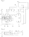
- a first strain inducing element 50 shown therein forms a weighing cell C and is comprised of a load cell of a type well known to those skilled in the art.
- This first strain inducing element 50 is of a generally rectangular configuration including a fixed rigid body 52 and a movable rigid body 57, substantially occupying respective ends of the first strain inducing element 50, and parallel upper and lower beams 54 connecting the fixed and movable rigid bodies 52 and 57 together and spaced a distance from each other while defining the cavity 51.
- a portion of the fixed rigid body 52 confronting the cavity 51 has a support recess 52a defined therein, and a second strain inducing element 1 forming a displacement sensor S is accommodated within a cavity 51 defined in the first strain inducing element 50 forming the weighing cell C.
- the second strain inducing element 1 is in turn supported by the fixed rigid body 52 with one end thereof received in the support recess 52a and connected therewith through a set bolt 53 so as to have its longitudinal sense lying substantially parallel to the longitudinal sense of the first strain inducing element 50.
- the first strain inducing element 50 is supported with the fixed rigid body 52 rigidly secured to any suitable mount B such as, for example, a framework installed on a floor.
- the movable rigid body 57 of the first strain inducing element 50 is coupled with a weighing table 59 on which an article M to be weighed is placed.
- Each of the upper and lower beams 54 has a pair of regions of easy flexure or strain generating regions 55, and four strain gauges 56 are fixedly mounted on respective portions of outer surfaces of the upper and lower beams 54, which are aligned with the associated regions of easy flexure 55, so that a load F imposed by the article M to be weighed on the movable rigid body 57 can be detected.
- the weighing cell C incorporating the displacement sensor S is suitably utilized where vibrations occurring at the site of installation of the weight checker and/or the combinational weighing apparatus are apt to reduce the accuracy of weight measurement.
- the displacement sensor S and the weighing cell C are so positioned as to have their longitudinal center axes S1 and C1 lying in the same vertical plane as shown in Fig. 2.
- an equal amount of rolling moment acting about a horizontal axis acts on both of the displacement sensor S and the weighing cell C and, therefore, an undesirable influence brought about by the rolling moment RM on the displacement sensor S and that on the weighing cell C are advantageously counterbalanced to each other, thereby enabling the displacement sensor S to accurately detect a displacement, that is, a vibration, acting on the weighing cell C in the vertical direction.
- the displacement sensor S is accommodated within the cavity 51 of the first strain inducing element 50 forming the weighing cell C such as realized according to the first preferred embodiment of the present invention shown in and described with reference to Figs. 1 and 2 and, therefore, the weighing apparatus as a whole can have a reduced size.
- the displacement sensor S and the weighing cell C are fixedly supported on the mount B, that is, at the same site on the floor, the same phase of vibration (floor vibration) acts on the displacement sensor S and the weighing cell C and, consequently, the vibration component contained in the weight signal W can be accurately removed on the basis of the displacement signal D outputted from the displacement sensor S, making it possible to accomplish a precise and accurate weight measurement.
- the displacement sensor S to be accommodated within the cavity 51 may have an increased size.
- a displacement sensor of a type wherein a single plate-like beam is employed between the fixed and movable rigid bodies and a strain gauge is mounted on such single plate-like beam may be concurrently employed.
- the second strain inducing element 1, that is, the displacement sensor S shown therein comprises a fixed cube or block 10, a movable cube or block 11 and generally rectangular upper and lower thin plates 21 forming respective upper and lower beams and extending parallel to each other between the fixed and movable cubes 10 and 11.
- the upper and lower beams 20 extend parallel to each other and in a direction perpendicular to the direction in which vibration acts.
- Each of the upper and lower rectangular thin plates 21 forming the respective upper and lower beams 20 has regions of easy flexure or strain generating regions 21a formed therein at respective location adjacent the movable and fixed cubes 10 and 11 so as to extend in a direction perpendicular to the longitudinal axis of the rectangular thin plates 21.
- These regions of easy flexure 21a in each of the upper and lower thin plates 21 are regions about which the respective rectangular thin plate 20 is most susceptible to flex.
- the strain inducing element 1 undergoes a cyclic parallel motion in which the movable cube 10 displaces cyclically relative to the fixed cube 11 in a direction conforming to the direction in which the vibratory motion takes place.
- Each of the fixed and movable cubes 10 and 11 is in the form of a generally cubic block made of metal such as, for example, stainless steel and has a pair of generally L-sectioned recesses formed therein so as to leave positioning shoulders generally identified by 12.
- the upper and lower thin plates 21 are so positioned as to straddle the fixed and movable cubes 10 and 11 with their opposite ends held in abutment with the associated positioning shoulders 12 while extending parallel to each other, thereby securing the position of each of the upper and lower thin plates 21 relative to the fixed and movable cubes 10 and 11 in the longitudinal direction of the sensor.
- the opposite ends of the upper and lower thin plates 21 are, after having been positioned in the manner described above, spot-welded at 21b to the fixed and movable cubes 10 and 11 by the use of any known spot-welding technique, for example, a YAG laser welding technique.
- the strain inducing element 1 When in use, the strain inducing element 1 is mounted in a machine or a vehicle with the fixed cube 10 rigidly secured to the machine component part and, for this purpose, the fixed cube 10 is formed with a plurality of internally threaded bolt receiving holes 13. It is to be noted that each of the fixed and movable cubes 10 and 11 may have a bolt insertion hole 14 formed therein for the convenience of assemblage.
- the upper and lower thin plates 21 form the respective upper and lower beams 20 extending between the fixed and movable cubes 10 and 11 with their opposite ends spot-welded thereto.
- Each of these upper and lower plates 21 is in the form of a rectangular stainless steel plate having a thickness of about 0.3mm. This thickness of the stainless steel plate for each of the upper and lower thin plates 21 is preferred to be not greater than 1.0mm and is more preferably not greater than 0.5mm.
- each of the upper and lower thin plate 21 has a strain gauge 23 formed directly on one surface thereof.
- This strain gauge 23 is an example of a displacement detecting element which provides an electric signal of a magnitude proportional to the amount of displacement of the movable rigid cube 11 in the vertical direction. More specifically, as best shown in Fig. 4, the strain gauge 23 is formed on one surface of the rectangular upper thin plate 21 through an electrically insulating layer 22. These regions of easy flexure 21a referred to above and formed in each of the rectangular upper and lower thin plates 21 are defined by corresponding transverse grooves 24 formed on the surface of the respective thin plate 21 opposite to the surface thereof on which the strain gauge 23 is formed. It is to be noted that, although in the foregoing embodiment the strain gauges 23 are formed on the two thin plates, that is, the upper and lower thin plates 21, the strain gauge 23 on one of the upper and lower thin plates may be dispensed with.
- the strain gauge 23 on the rectangular thin plate 21 includes, as best shown in Fig. 4, strain sensing elements 23a in the form of resistance wires disposed so as to traverse the respective regions of easy flexure 21a, that is, the respective grooves 24, first to third conductors 23b and terminal elements 23c connected electrically with the first to third conductors 23b.
- the first or center conductor 23b connects the strain sensing elements 23a together while the second and third conductors 23b are connected with respective ends of the strain sensing elements 23a.
- This strain gauge 23 is so designed and so operable that, when tensile stress and compressive stress are built up on respective surface regions of the rectangular upper thin plate 21 corresponding to the regions of easy flexure 21a as a result of deformation of the strain inducing element 1 shown in Fig. 3, the electric resistances of the strain sensing elements 23a best shown in Fig. 4 increases and decreases, respectively, in proportion to the magnitudes of the tensile and compressive stresses so built up. Respective changes in resistance of the strain sensing elements 23a are outputted from the terminal elements 23c to an external processing unit through a cable (not shown) so that the external processing unit can provide an indication of the magnitude of displacement brought about by the vibration component that has acted on the strain inducing element 1.
- a relatively large thin plate material 30 made of metal such as, for example, stainless steel is prepared and a plurality of grooves 31 are formed on one surface of the thin plate material 30 so as to extend parallel to each other while being spaced an equal distance from each other.
- These grooves 31 are, in the practice of the present invention, formed in the following manner by the use of a half-etching technique.
- a resist layer 32 is formed on one surface of the thin plate material 30, and a masking film 33 having a pattern of light shielding areas 33a and light transmitting areas 33b is then placed over the resist layer 32. Then, rays of light from a light source positioned above the thin plate material 30 are projected onto the thin plate material 30 to allow portions of the resist layer 32 aligned with the light transmitting areas 33b of the masking film 33 to be cured.
- those portions of the resist layer 32 aligned with the light transmitting areas 33b of the masking film 33 have been cured, and after the making film 33 has subsequently been removed, those portions of the resist layers 32 which have not been exposed to the rays of light, that is, which are aligned with the light shielding areas 33a of the masking film 33 and are hence non-cured, are removed off in contact with a developer, thereby leaving only the cured portions 32a of the resist layer 32 on the surface of the thin plate material 30 as shown in Fig. 7.
- portions of the thin plate material 30 which are not covered by the cured portions 32a of the resist layer 32 are etched off in contact with an etching solution to a desired or required depth, followed by removal of the cured portions 32a of the resist layer 32.
- the thin plate material 30 having the grooves 31 formed thereon as shown in Fig. 5 is obtained.
- each strain gauge 23 so obtained is of a structure in which, as best shown in Fig. 10, at least strain sensing elements 23a and conductors 23b are laminated and are in turn covered by a protective layer 23d formed by the use of a screen printing process.
- the thin plate material 30 having a matrix pattern of the strain gauges 23 and the parallel grooves 31 formed on the respective opposite surfaces thereof is scribed, or otherwise cut, along grid lines, shown by the phantom lines b in Fig. 9, into a plurality of pieces, one piece corresponding to the individual rectangular thin plate 21 shown in Fig. 4 having the strain gauge 23 and the grooves 24 formed on the respective opposite surface thereof.
- the thin plate material 30 having the strain gauges 23 and the parallel grooves 31 provides a plurality of the individual rectangular thin plates 21 having the strain gauges 23 and the grooves 24.
- the individual rectangular upper thin plate 21 having the strain gauge 23 and the grooves 24 is mounted on the fixed and movable cubes 10 and 11 shown in Fig. 3 in the manner which will now be described with particular reference to Fig. 11 showing a plan view of the sensor.
- the fixed and movable cubes 10 and 11 are sandwiched between side jig plates 40 with the positioning shoulders 12 in one of the fixed and movable cubes 10 and 11 confronting with the associated positioning shoulders 12 in the other of the fixed and movable cubes 10 and 11 and are tightly clamped therebetween by means of fastening bolts 41 passing through the bolt insertion holes 14 defined respectively in the fixed and movable cubes 10 and 11. In this way, the fixed and movable cubes 10 and 11 are fixed in position relative to each other.
- the rectangular upper thin plate 21 is, as shown by the phantom lines, placed so as to straddle the fixed and movable cubes 10 and 11 with its opposite ends held in abutment with the associated positioning shoulders 12 and, thereafter, a spot-welding is effected to the opposite ends of the upper thin plate 21 as shown by the phantom lines to secure the latter to the fixed and movable cubes 10 and 11.
- the assembly including the fixed and movable cubes 10 and 11, the jig plates 40 and the associated parts is turned 180 degrees about a longitudinal axis and, in a manner similar to the mounting of the upper thin plate 21, the rectangular lower thin plate 21 is mounted with its opposite ends spot-welded to the fixed and movable cubes 10 and 11. Thereafter, the jig plates 40 are removed, leaving the complete strain inducing element 1 as shown in Fig. 1.
- the displacement sensor in the form of the strain inducing element 1 is of a structure wherein each of the fixed and movable cubes 10 and 11 is in the form of a metal block, a weight required for a weight element can be secured in the movable cube 11.
- each of the upper and lower beams 20 is in the form of the thin plate 21 made of metal, each beam 20 can be made having a relatively small thickness and, therefore, the displacement sensor as a whole can be assembled compact in size.
- the formation of the regions of easy flexure 21a by the use of a non-mechanical process such as an etching process makes it possible to provide relatively thin region of easy flexure 21a and, therefore, flexure of the upper and lower thin plates 21 easily takes place even though a relatively small load is imposed on the displacement sensor. Accordingly, the movable cube 11 can be made small in size, making it possible to render the displacement sensor to be further compact in size.
- each of the upper and lower thin plates 21 is rigidly connected to the fixed and movable cubes 10 and 11 by means of the spot-weld deposits formed by the use of the YAG laser welding technique, relatively small weld joints are sufficient to integrate the upper and lower thin plates 21 and the fixed and movable cubes 10 and 11 together to provide the complete displacement sensor and, therefore, the displacement sensor as a whole can be made compact in size.
- the strain gauge 23 has been formed directly on the surface of at least one of the upper and lower thin plates 21 forming the respective upper and lower beams 20, it is possible to render those portions of such one of the upper and lower beams 20, which correspond in position to the respective regions of easy flexure 21a, to have a small thickness unlike the case in which a thin plate having a strain gauge formed thereon is bonded on the corresponding beam. Accordingly, it is possible to reduce the weight of the movable cube 11 and thence to reduce the size of the displacement sensor.
- the upper and lower thin plates 21 are successively welded at their opposite ends to the fixed and movable cubes 10 and 11 while the fixed and movable cubes 10 and 11 are retained in position relative to each other by using the jig plates 40 as shown in Fig. 11, there is no possibility that each of the upper and lower thin plates 21 is incorrectly fitted to either one of the fixed and movable cubes 10 and 11, facilitating an easy mounting of each thin plate 21 to the fixed and movable cubes 10 and 11.
- Fig. 12 illustrates a signal processing circuit.
- a weight signal W is outputted from a weight signal forming circuit 60A connected to the strain gauge 56 of the weighing cell C while a vibration signal (a displacement signal) D outputted form a vibration signal forming circuit 60B connected to the strain gauge 23 of the displacement sensor S.
- the weight signal W and the vibration signal D are fed to a compensating means 61 by which, after a difference in sensitivity between the weighing cell C and the displacement sensor S has been compensated for, a vibration component represented by the vibration signal D is subtracted from the weight represented by the weight signal W, to provide a corrected weight data CW in which a component of floor vibration has been eliminated.
- each of the upper and lower thin plates 21 shown in Fig. 3 has been described and shown as having the grooves 24 formed therein to define the regions of easy flexure 21a in the respective upper and lower beams 20.
- no groove 24 may be necessarily formed in each of the upper and lower thin plates 21, an example of which is shown in Fig. 13 showing a second preferred embodiment of the present invention.
- the thin plate 21 shown therein has two pairs of slits 24A, the slits 24A of each pair extending inwardly from opposite sides of the thin plate 21 in a direction close towards each other so as to leave the respective region of easy flexure 21a between the slits 24A of each pair.
- These slits 24A may be formed by the use of any know laser beam cutting technique. Except for the use of the two pairs of the slits 24A, in place of the grooves 24 shown in Figs. 3 and 4, to define the respective regions of easy flexure 21a in the thin plate 21, the thin plate 21 shown in Fig. 13 is substantially identical with that shown in Figs. 3 and 4 and, therefore, the details of thereof will not be reiterated for the sake of brevity.
- FIG. 14 A third preferred embodiment of the present invention is shown in Fig. 14.
- the upper and lower beams 54 have internally threaded through-holes 62 formed therein, respectively, so as to align with each other.
- Stopper bolts 63 which are examples of stopper members, are either adjustably or fixedly threaded into the respective through-holes 62 with their free end faces 63a spaced a distance from the movable rigid cube 11 of the second strain inducing element 1, that is, the displacement sensor S, so as to define the stroke of displacement of the movable rigid cube 11 of the second strain inducing element 1.
- the stopper bolts 63 serve as a means for regulating the stroke of displacement of the cantilevered displacement sensor S thereby to suppress an excessive displacement of the displacement sensor S which would otherwise result in damage to the displacement sensor S.
- the fixed rigid cube 10 of the second strain inducing element 1 is formed with a generally U-sectioned groove 16 opening towards the movable rigid cube 11 and leaving arms 16a and 16b that protrude towards the movable rigid cube 11.
- the movable rigid cube 11 is integrally formed with an elongated stopper 15 so as to extend intermediate between the upper and lower beams 20 with a free end thereof loosely received within the U-sectioned groove 16 in the fixed rigid cube 10.
- the U-sectioned groove 16 is so sized as to leave a slight gap G between the free end of the elongated stopper 15 and each of the arms 16a and 16b, respectively.
- the U-sectioned groove 16 and the elongated stopper 15 define a means for regulating the stroke of displacement of the movable rigid cube 11 relative to the fixed rigid cube 10 thereby to suppress an excessive displacement of the movable rigid cube 11 relative to the fixed rigid cube 10 which would otherwise damage the weighing cell C.
- the U-sectioned groove 16 and the elongated stopper 15 may be reversed in position relative to each other although the U-sectioned groove 16 and the elongated stopper 15 have been shown and described as formed in the fixed rigid cube 10 and the movable rigid cube 11, respectively.
- the means for regulating the stroke of displacement of the movable rigid cube 11 relative to the fixed rigid cube 10 thereby to suppress an excessive displacement of the movable rigid cube 11 relative to the fixed rigid cube 10 is constituted by a generally rectangular plate 18 fixedly secured to the fixed rigid cube 10 by means of set bolts (not shown) and having a generally U-sectioned groove 16 defined therein so as to leave arms 16a and 16b protruding towards the movable rigid cube 11, and a generally T-shaped stopper plate 17 fixedly secured to the movable rigid cube 11 by means of set bolts (not shown) and having an elongated stopper 15 protruding towards the fixed rigid cube 10 with a free end thereof terminating within the U-sectioned groove 16.
- the U-sectioned groove 16 is so sized as to leave a slight gap G between the free end of the elongated stopper 15 and each of the arms 16a and 16b, respectively.
- the rectangular plate 18 and the stopper plate 17 may be reversed in position relative to each other although the rectangular plate 18 and the stopper plate 17 have been shown and described as secured to the fixed rigid cube 10 and the movable rigid cube 11, respectively.
- FIG. 17 showing a sixth preferred embodiment of the present invention
- the second strain inducing element 1 that is, the displacement sensor S
- the fixed rigid body 52 of the first strain inducing element 50 that is, the weighing cell C
- the second strain inducing element 1 shown in Fig. 16 is externally carried by the fixed rigid body 52 of the first strain inducing element 50.
- the second strain inducing element 1 has its fixed rigid cube 10 fixedly connected in a side-by-side fashion to a side face of the fixed rigid body 52 of the first strain inducing element 50 by means of a set bolt 65 extending through the fixed rigid cube 10 in a direction parallel to the principal plane of any one of the upper and lower beams 20 of the second strain inducing element 1, a free end of said set bolt 65 being threaded into the fixed rigid body 52 of the first strain inducing element 50.
- any one of the sixth preferred embodiments of the present invention shown in Fig. 17 since the displacement sensor S is mounted on the base B at the same position where the fixed rigid body 52 of the weighing cell C is mounted, the same phase of vibration (floor vibration) acts on the displacement sensor S and the weighing cell C and, consequently, as described with reference to the signal processing circuit shown in Fig. 12, the vibration component contained in the weight signal W can be accurately detected and removed on the basis of the displacement signal D outputted from the displacement sensor S, making it possible to accomplish a precise and accurate weight measurement.
- floor vibration floor vibration
- the displacement sensor S utilizing the beams 20 in the form of the thin plates 21 is compact in size, even securement of the displacement sensor S to the fixed rigid body 52 of the weighing cell C does not results in generation of a relatively large amount of strains in the fixed rigid body 52 of the weighing cell C and, accordingly, the strain characteristic of the load on the weighing cell C will not be adversely affected.
- those portions of the upper and lower thin plates 21 may be defined as the respective regions of easy flexure 21a.
- each of the upper and lower beams 20 may not be constituted by the thin plate 21 and, instead thereof, the upper and lower beams may be formed integrally with the fixed and movable rigid bodies 10 and 11.
- strain gauge 23 has been described in the form of a strain gauge including metal thin films, a semiconductor thin-film strain gauge such as made up of films of hydrogenated amorphous silicon.
- a combination of a weighing cell (C) with a displacement sensor (S) is disclosed, in which the weighing cell (C) includes a strain inducing element (1) having a strain generating region (55) at which strain is generated in response to application of a load thereto, and a strain gauge (56) for detecting the strain generated in the strain generating region (55), and the displacement sensor (S) includes a fixed rigid component (10), a movable rigid components (11) forming a weight element, a generally elongated beam member (20) rigidly secured at opposite ends to the fixed and movable rigid components (10, 11), respectively, so as to extend between the fixed and movable rigid components (10, 11), and a displacement detecting element (23) mounted on the elongated beam member (20) for outputting an electric signal of a magnitude proportional to the amount of displacement of the movable rigid component (11) in a direction generally perpendicular to the elongated beam member (20).
- the strain inducing element (1) of the weighing cell includes a fixed rigid body (52) adapted to be secured to a base (B) and a movable rigid body (57) adapted to receive the load to be measured, and first and second beams (54) rigidly secured at opposite ends to the fixed and movable rigid bodies (52, 57) and extending parallel to each other between the fixed and movable rigid bodies (52, 57).
- the displacement sensor (S) is fixedly carried by the fixed rigid body (52) of the weighing cell (C).
Landscapes
- Physics & Mathematics (AREA)
- General Physics & Mathematics (AREA)
- Measurement Of Force In General (AREA)
- Pressure Sensors (AREA)
Applications Claiming Priority (2)
| Application Number | Priority Date | Filing Date | Title |
|---|---|---|---|
| JP202849/93 | 1993-07-22 | ||
| JP20284993A JP3314107B2 (ja) | 1993-07-22 | 1993-07-22 | 加速度センサの取付構造 |
Publications (2)
| Publication Number | Publication Date |
|---|---|
| EP0635703A1 true EP0635703A1 (fr) | 1995-01-25 |
| EP0635703B1 EP0635703B1 (fr) | 1999-01-13 |
Family
ID=16464215
Family Applications (1)
| Application Number | Title | Priority Date | Filing Date |
|---|---|---|---|
| EP94111446A Expired - Lifetime EP0635703B1 (fr) | 1993-07-22 | 1994-07-21 | Détecteur de charge avec capteur de déplacement et dispositif de pesage l'utilisant |
Country Status (4)
| Country | Link |
|---|---|
| US (1) | US5440077A (fr) |
| EP (1) | EP0635703B1 (fr) |
| JP (1) | JP3314107B2 (fr) |
| DE (1) | DE69415885T2 (fr) |
Cited By (3)
| Publication number | Priority date | Publication date | Assignee | Title |
|---|---|---|---|---|
| EP2887040B1 (fr) * | 2013-12-18 | 2017-12-13 | Eurailscout Inspection & Analysis b.v. | Dispositif et procédé de détermination de la force de contact entre deux composants |
| WO2019229549A1 (fr) | 2018-05-31 | 2019-12-05 | Nanolever S.R.L. | Dispositif de cellule dynamométrique |
| IT201900021000A1 (it) | 2019-11-12 | 2021-05-12 | Nanolever S R L | Dispositivo di pesatura e corrispondente procedimento |
Families Citing this family (24)
| Publication number | Priority date | Publication date | Assignee | Title |
|---|---|---|---|---|
| EP0756158B1 (fr) * | 1995-07-26 | 2002-10-02 | ISHIDA CO., Ltd. | Appareil de pesée |
| DE19926513A1 (de) * | 1999-06-10 | 2000-12-21 | Bsh Bosch Siemens Hausgeraete | Kochfeld mit Wägeeinheit |
| US6178829B1 (en) * | 1999-06-29 | 2001-01-30 | Kavlico Corporation | Redundant linkage and sensor assembly |
| EP1347273A1 (fr) * | 2002-03-23 | 2003-09-24 | Soehnle-Waagen GmbH & Co. KG | Capteur de pesage |
| WO2004055624A2 (fr) * | 2002-12-02 | 2004-07-01 | Conair Corporation | Systeme de controle de bascule et eponge |
| US7275452B2 (en) * | 2003-03-25 | 2007-10-02 | Kulite Semiconductor Products, Inc. | Stop assembly for a beam type load cell |
| JP3808841B2 (ja) * | 2003-04-02 | 2006-08-16 | 株式会社イシダ | 重量検出装置 |
| US7086299B2 (en) * | 2003-05-08 | 2006-08-08 | Kulite Semiconductor Products, Inc. | Multi-load beam apparatus to prevent improper operation due to off-axis loads |
| US7048096B2 (en) * | 2003-12-08 | 2006-05-23 | Russell Ozechowski | Incremental braking apparatus and method of braking |
| JP4655511B2 (ja) * | 2004-05-31 | 2011-03-23 | トヨタ自動車株式会社 | 圧電式制振装置の構成方法 |
| JP2007322188A (ja) * | 2006-05-31 | 2007-12-13 | Oki Electric Ind Co Ltd | Memsデバイス |
| JP2008201272A (ja) | 2007-02-20 | 2008-09-04 | Denso Corp | 衝突検知手段および保護システム |
| US7624637B2 (en) * | 2007-09-14 | 2009-12-01 | Kulite Semiconductor Products, Inc. | Beam accelerometer with limiting apparatus |
| JP5583428B2 (ja) * | 2010-02-19 | 2014-09-03 | 大和製衡株式会社 | ダミーロードセル |
| JP5840430B2 (ja) * | 2011-09-14 | 2016-01-06 | 大和製衡株式会社 | ロードセルおよびその製造方法 |
| NL2008635C2 (nl) * | 2012-04-13 | 2013-10-16 | Marel Stork Poultry Proc Bv | Inrichting voor het wegen van slachtproducten en werkwijze voor toepassing daarvan. |
| WO2014068761A1 (fr) * | 2012-11-02 | 2014-05-08 | 株式会社 エー・アンド・デイ | Cellule de charge |
| US10041856B2 (en) * | 2016-03-01 | 2018-08-07 | Cleveland Electric Laboratories Company | Method and apparatus for measuring physical displacement |
| CN110044418B (zh) * | 2019-04-28 | 2025-03-07 | 深圳市力准传感技术有限公司 | 一体组合式位移测力计 |
| EP3845872B1 (fr) * | 2019-12-30 | 2023-07-12 | Bizerba SE & Co. KG | Cellule de pesage |
| EP3845873B1 (fr) | 2019-12-30 | 2023-02-15 | Bizerba SE & Co. KG | Console d'étagère |
| EP3845874B1 (fr) | 2019-12-30 | 2024-12-04 | Bizerba SE & Co. KG | Étagère |
| JP2023109353A (ja) * | 2022-01-27 | 2023-08-08 | Imv株式会社 | 加速度ピックアップ校正用治具 |
| DE102022128780A1 (de) * | 2022-10-28 | 2024-05-08 | Sartorius Lab Instruments Gmbh & Co. Kg | Verfahren zum Herstellen eines Grundkörpers eines Wägeaufnehmers und Grundkörper |
Citations (6)
| Publication number | Priority date | Publication date | Assignee | Title |
|---|---|---|---|---|
| EP0122796A1 (fr) * | 1983-04-14 | 1984-10-24 | Kabushiki Kaisha Ishida Koki Seisakusho | Balance |
| EP0129249A2 (fr) * | 1983-06-21 | 1984-12-27 | Kabushiki Kaisha Ishida Koki Seisakusho | Dispositif de pesage |
| EP0147238A2 (fr) * | 1983-12-28 | 1985-07-03 | Kabushiki Kaisha Ishida Koki Seisakusho | Capteur de poids |
| EP0289113A2 (fr) * | 1987-02-27 | 1988-11-02 | Yamato Scale Company, Limited | Dispositif contrebalancé de pesage |
| EP0430695A2 (fr) * | 1989-12-01 | 1991-06-05 | ISHIDA CO., Ltd. | Dispositif de pesage |
| EP0432979A2 (fr) * | 1989-12-08 | 1991-06-19 | Yamato Scale Co., Ltd. | Balance pour l'opération sous conditions oscillantes |
Family Cites Families (5)
| Publication number | Priority date | Publication date | Assignee | Title |
|---|---|---|---|---|
| US4379495A (en) * | 1981-04-27 | 1983-04-12 | Hobart Corporation | Weighing scale with low susceptibility to vibration |
| DE3236532A1 (de) * | 1982-10-02 | 1984-04-05 | Philips Patentverwaltung Gmbh, 2000 Hamburg | Kraftaufnehmer |
| US4657097A (en) * | 1984-02-13 | 1987-04-14 | Reliance Electric Company | Load cell |
| CH665287A5 (fr) * | 1985-12-17 | 1988-04-29 | Scaime | Capteur a jauge de contrainte pour la mesure de forces. |
| US5154247A (en) * | 1989-10-31 | 1992-10-13 | Teraoka Seiko Co., Limited | Load cell |
-
1993
- 1993-07-22 JP JP20284993A patent/JP3314107B2/ja not_active Expired - Fee Related
-
1994
- 1994-07-20 US US08/277,748 patent/US5440077A/en not_active Expired - Lifetime
- 1994-07-21 EP EP94111446A patent/EP0635703B1/fr not_active Expired - Lifetime
- 1994-07-21 DE DE69415885T patent/DE69415885T2/de not_active Expired - Lifetime
Patent Citations (6)
| Publication number | Priority date | Publication date | Assignee | Title |
|---|---|---|---|---|
| EP0122796A1 (fr) * | 1983-04-14 | 1984-10-24 | Kabushiki Kaisha Ishida Koki Seisakusho | Balance |
| EP0129249A2 (fr) * | 1983-06-21 | 1984-12-27 | Kabushiki Kaisha Ishida Koki Seisakusho | Dispositif de pesage |
| EP0147238A2 (fr) * | 1983-12-28 | 1985-07-03 | Kabushiki Kaisha Ishida Koki Seisakusho | Capteur de poids |
| EP0289113A2 (fr) * | 1987-02-27 | 1988-11-02 | Yamato Scale Company, Limited | Dispositif contrebalancé de pesage |
| EP0430695A2 (fr) * | 1989-12-01 | 1991-06-05 | ISHIDA CO., Ltd. | Dispositif de pesage |
| EP0432979A2 (fr) * | 1989-12-08 | 1991-06-19 | Yamato Scale Co., Ltd. | Balance pour l'opération sous conditions oscillantes |
Cited By (3)
| Publication number | Priority date | Publication date | Assignee | Title |
|---|---|---|---|---|
| EP2887040B1 (fr) * | 2013-12-18 | 2017-12-13 | Eurailscout Inspection & Analysis b.v. | Dispositif et procédé de détermination de la force de contact entre deux composants |
| WO2019229549A1 (fr) | 2018-05-31 | 2019-12-05 | Nanolever S.R.L. | Dispositif de cellule dynamométrique |
| IT201900021000A1 (it) | 2019-11-12 | 2021-05-12 | Nanolever S R L | Dispositivo di pesatura e corrispondente procedimento |
Also Published As
| Publication number | Publication date |
|---|---|
| JP3314107B2 (ja) | 2002-08-12 |
| DE69415885D1 (de) | 1999-02-25 |
| EP0635703B1 (fr) | 1999-01-13 |
| US5440077A (en) | 1995-08-08 |
| JPH0735766A (ja) | 1995-02-07 |
| DE69415885T2 (de) | 1999-07-01 |
Similar Documents
| Publication | Publication Date | Title |
|---|---|---|
| US5440077A (en) | Combined weighting and displacement sensor and weighing apparatus using the same | |
| EP0616199B1 (fr) | Boîte dynamométrique et dispositif de pesage l'utilisant | |
| EP0537347B1 (fr) | Capteur d'accélérations avec un contrÔle automatique | |
| US5512713A (en) | Load cell having a hollow and a strain gauge formed on a substrate attached inside the hollow | |
| EP1292832B1 (fr) | Accelerometre rotatif piezo-electrique | |
| US5220971A (en) | Shear beam, single-point load cell | |
| US5756943A (en) | Load cell | |
| US6910392B2 (en) | Bending beam load cell with torque sensitivity compensation | |
| JP2834282B2 (ja) | ロードセル | |
| US6633008B2 (en) | Electronic force sensing shock resistant load cell | |
| EP0114530B1 (fr) | Balance avec une cellule dynamométrique | |
| US4450922A (en) | Force sensing device for measurement apparatus | |
| JPH0772026A (ja) | 起歪体構造物およびこの起歪体構造物を用いた多軸力検出センサ | |
| EP0602606B1 (fr) | Procédé de fabrication de capteurs de contrainte | |
| JPH05248925A (ja) | ロードセル、ロードセルの製造方法、計量器及び計量方法 | |
| JPH032824Y2 (fr) | ||
| JPH0688756A (ja) | 重量測定装置と方法 | |
| US10908039B2 (en) | Load cell assembly including cavities to buffer horizontal shear forces | |
| JP3852291B2 (ja) | ロードセル | |
| JP2749158B2 (ja) | 貼付型電気容量ひずみゲージ | |
| CN120721198A (zh) | 一种多桥式称重装置 | |
| JPH0812101B2 (ja) | ロードセル | |
| JPH03105220A (ja) | ロードセル |
Legal Events
| Date | Code | Title | Description |
|---|---|---|---|
| PUAI | Public reference made under article 153(3) epc to a published international application that has entered the european phase |
Free format text: ORIGINAL CODE: 0009012 |
|
| AK | Designated contracting states |
Kind code of ref document: A1 Designated state(s): DE FR GB |
|
| 17P | Request for examination filed |
Effective date: 19950116 |
|
| 17Q | First examination report despatched |
Effective date: 19961217 |
|
| GRAG | Despatch of communication of intention to grant |
Free format text: ORIGINAL CODE: EPIDOS AGRA |
|
| GRAG | Despatch of communication of intention to grant |
Free format text: ORIGINAL CODE: EPIDOS AGRA |
|
| GRAH | Despatch of communication of intention to grant a patent |
Free format text: ORIGINAL CODE: EPIDOS IGRA |
|
| GRAH | Despatch of communication of intention to grant a patent |
Free format text: ORIGINAL CODE: EPIDOS IGRA |
|
| GRAA | (expected) grant |
Free format text: ORIGINAL CODE: 0009210 |
|
| AK | Designated contracting states |
Kind code of ref document: B1 Designated state(s): DE FR GB |
|
| ET | Fr: translation filed | ||
| REF | Corresponds to: |
Ref document number: 69415885 Country of ref document: DE Date of ref document: 19990225 |
|
| PLBE | No opposition filed within time limit |
Free format text: ORIGINAL CODE: 0009261 |
|
| STAA | Information on the status of an ep patent application or granted ep patent |
Free format text: STATUS: NO OPPOSITION FILED WITHIN TIME LIMIT |
|
| 26N | No opposition filed | ||
| REG | Reference to a national code |
Ref country code: GB Ref legal event code: IF02 |
|
| PGFP | Annual fee paid to national office [announced via postgrant information from national office to epo] |
Ref country code: FR Payment date: 20100805 Year of fee payment: 17 Ref country code: DE Payment date: 20100714 Year of fee payment: 17 |
|
| PGFP | Annual fee paid to national office [announced via postgrant information from national office to epo] |
Ref country code: GB Payment date: 20100721 Year of fee payment: 17 |
|
| GBPC | Gb: european patent ceased through non-payment of renewal fee |
Effective date: 20110721 |
|
| REG | Reference to a national code |
Ref country code: FR Ref legal event code: ST Effective date: 20120330 |
|
| PG25 | Lapsed in a contracting state [announced via postgrant information from national office to epo] |
Ref country code: FR Free format text: LAPSE BECAUSE OF NON-PAYMENT OF DUE FEES Effective date: 20110801 Ref country code: DE Free format text: LAPSE BECAUSE OF NON-PAYMENT OF DUE FEES Effective date: 20120201 |
|
| REG | Reference to a national code |
Ref country code: DE Ref legal event code: R119 Ref document number: 69415885 Country of ref document: DE Effective date: 20120201 |
|
| PG25 | Lapsed in a contracting state [announced via postgrant information from national office to epo] |
Ref country code: GB Free format text: LAPSE BECAUSE OF NON-PAYMENT OF DUE FEES Effective date: 20110721 |