EP0636562A1 - Dispositif pour couper du ruban - Google Patents
Dispositif pour couper du ruban Download PDFInfo
- Publication number
- EP0636562A1 EP0636562A1 EP94109579A EP94109579A EP0636562A1 EP 0636562 A1 EP0636562 A1 EP 0636562A1 EP 94109579 A EP94109579 A EP 94109579A EP 94109579 A EP94109579 A EP 94109579A EP 0636562 A1 EP0636562 A1 EP 0636562A1
- Authority
- EP
- European Patent Office
- Prior art keywords
- tape
- cutter
- upper blade
- cutter portion
- cutting
- Prior art date
- Legal status (The legal status is an assumption and is not a legal conclusion. Google has not performed a legal analysis and makes no representation as to the accuracy of the status listed.)
- Withdrawn
Links
- 238000005520 cutting process Methods 0.000 claims abstract description 80
- 230000000875 corresponding effect Effects 0.000 description 21
- 239000002184 metal Substances 0.000 description 19
- 238000003780 insertion Methods 0.000 description 9
- 239000000956 alloy Substances 0.000 description 6
- 239000011347 resin Substances 0.000 description 6
- 229920005989 resin Polymers 0.000 description 6
- 229910045601 alloy Inorganic materials 0.000 description 5
- 239000012790 adhesive layer Substances 0.000 description 4
- 210000000078 claw Anatomy 0.000 description 4
- 230000037431 insertion Effects 0.000 description 4
- 238000000034 method Methods 0.000 description 4
- 229930182556 Polyacetal Natural products 0.000 description 3
- 239000000463 material Substances 0.000 description 3
- 229920006324 polyoxymethylene Polymers 0.000 description 3
- 210000003813 thumb Anatomy 0.000 description 2
- 235000014121 butter Nutrition 0.000 description 1
- 230000002079 cooperative effect Effects 0.000 description 1
- 230000000694 effects Effects 0.000 description 1
- 238000012986 modification Methods 0.000 description 1
- 230000004048 modification Effects 0.000 description 1
Images


Classifications
-
- B—PERFORMING OPERATIONS; TRANSPORTING
- B23—MACHINE TOOLS; METAL-WORKING NOT OTHERWISE PROVIDED FOR
- B23D—PLANING; SLOTTING; SHEARING; BROACHING; SAWING; FILING; SCRAPING; LIKE OPERATIONS FOR WORKING METAL BY REMOVING MATERIAL, NOT OTHERWISE PROVIDED FOR
- B23D35/00—Tools for shearing machines or shearing devices; Holders or chucks for shearing tools
- B23D35/008—Means for changing the cutting members
-
- B—PERFORMING OPERATIONS; TRANSPORTING
- B26—HAND CUTTING TOOLS; CUTTING; SEVERING
- B26D—CUTTING; DETAILS COMMON TO MACHINES FOR PERFORATING, PUNCHING, CUTTING-OUT, STAMPING-OUT OR SEVERING
- B26D7/00—Details of apparatus for cutting, cutting-out, stamping-out, punching, perforating, or severing by means other than cutting
- B26D7/01—Means for holding or positioning work
- B26D7/015—Means for holding or positioning work for sheet material or piles of sheets
-
- B—PERFORMING OPERATIONS; TRANSPORTING
- B26—HAND CUTTING TOOLS; CUTTING; SEVERING
- B26D—CUTTING; DETAILS COMMON TO MACHINES FOR PERFORATING, PUNCHING, CUTTING-OUT, STAMPING-OUT OR SEVERING
- B26D7/00—Details of apparatus for cutting, cutting-out, stamping-out, punching, perforating, or severing by means other than cutting
- B26D7/26—Means for mounting or adjusting the cutting member; Means for adjusting the stroke of the cutting member
- B26D7/2614—Means for mounting the cutting member
-
- B—PERFORMING OPERATIONS; TRANSPORTING
- B41—PRINTING; LINING MACHINES; TYPEWRITERS; STAMPS
- B41J—TYPEWRITERS; SELECTIVE PRINTING MECHANISMS, i.e. MECHANISMS PRINTING OTHERWISE THAN FROM A FORME; CORRECTION OF TYPOGRAPHICAL ERRORS
- B41J11/00—Devices or arrangements of selective printing mechanisms, e.g. ink-jet printers or thermal printers, for supporting or handling copy material in sheet or web form
- B41J11/66—Applications of cutting devices
- B41J11/70—Applications of cutting devices cutting perpendicular to the direction of paper feed
- B41J11/703—Cutting of tape
-
- B—PERFORMING OPERATIONS; TRANSPORTING
- B26—HAND CUTTING TOOLS; CUTTING; SEVERING
- B26D—CUTTING; DETAILS COMMON TO MACHINES FOR PERFORATING, PUNCHING, CUTTING-OUT, STAMPING-OUT OR SEVERING
- B26D7/00—Details of apparatus for cutting, cutting-out, stamping-out, punching, perforating, or severing by means other than cutting
- B26D2007/0012—Details, accessories or auxiliary or special operations not otherwise provided for
- B26D2007/0062—Rounding off the end of self adhesive labels on tapes
Definitions
- the present invention relates to a tape cutter capable of cutting a tape produced in a tape printer, and more particularly to the tape cutter being capable of cutting a variety of tapes with different widths.
- Tapes produced with a tape printer can be used for a variety of purposes.
- Various objectives for such tapes require a variety of tapes with different widths. For example, a tape for being adhered to a video cassette as an identification label would be wider than a tape adhered to an audio cassette.
- the tape cutter is capable of cutting the four corners of tapes into rounded shapes, which are more aesthetically pleasing than cutting the tapes ends into straight lines.
- a plurality of interchangeable blade holders are provided to the tape cutter.
- a blade is provided in each blade holder.
- Each blade is shaped for cutting the corners of the corresponding width tape into rounded shapes.
- a fixed blade is fixed to the interior of the tape cutter so as to confront a blade holder mounted in the tape cutter.
- the blade holder corresponding to the width of the tape to be cut is mounted in the tape cutter.
- one end of a tape to be cut is inserted into a tape insertion slot of the tape cutter and cut by moving the blade holder downward.
- the operation is repeated on the other end of the tape so that both ends of the tape are cut to a predetermined shape by the blade in the blade holder in cooperation with the fixed blade.
- the blade holder is removed and the correct width blade holder exchanged therefor.
- the tape cutter thus allows cutting both ends of a tape into predetermined shapes according to the tape width of each tape.
- the distance from the edge of an inserted end of the tape to the blade is set to a fixed length. Because of this, the tape can only be cut at the same standard distance from a lengthwise edge. As a result, there are limitations to the variations in tapes that can be produced by the tape cutter.
- the tape cutter requires maintaining a plurality of individual blade holders separately from the tape cutter.
- Each of the blade holders is small and easily lost. Also, when changing blade holders a user might be cut by accidentally touching the blade provided in each blade holder.
- a tape cutter for cutting a tape having a width comprises a lower cutter portion with a blade receiving stand fixed thereto, the blade receiving stand having a cutting edge; an upper cutter portion provided connected to the lower cutter portion so that the upper cutter portion is movable relative to the lower cutter portion from an open condition to a cutting condition; an upper blade having a cutting edge, the upper blade being provided so as to move toward the blade receiving stand when the upper cutter portion is moved into the cutting condition, the cutting edge of the blade receiving stand and the cutting edge of the upper blade defining a cutting area when upper cutter portion is in the cutting condition; and a tape guide for guiding the tape toward the cutting area so that the tape is brought into a predetermined relative posture with the cutting area.
- a pair of positioning members are provided on either side of the upper blade separated by a distance in the widthwise direction, the distance corresponding to the width of the tape, so that a tape guided toward the cutting area by the tape guide will pass between the positioning members and be prevented from moving in the widthwise direction.
- a tape stopper is provided for stopping a tape guided by the tape guide after an end of the tape passes between the upper blade and the blade receiving stand and past the cutting area.
- a tape margin adjusting means is also provided for adjusting a distance between the tape stopper and the cutting area.
- each upper blade of the plurality of not-in-use upper blade holders having a width corresponding to a width of one of a plurality of different width tapes, are provided to the tape cutter, in a still further aspect of the present invention the upper cutter portion is movable relative to the lower cutter portion from the open condition to the cutting condition and further to a closed condition, a housing space being formed between the upper cutter portion and the lower cutter portion when the upper cutter portion is in the closed condition, the housing space being capable of housing the plurality of not-in-use upper blade holders.
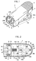
- a tape cutter 1 according to a preferred embodiment of the present invention will be described while referring to the accompanying drawings wherein like parts and components are designated by the same reference numerals to avoid duplicating description.
- the tape cutter 1 includes an elongated upper cutter portion 2 and an elongated lower cutter portion 3.
- a pair of axes 4 are provided for connecting the upper cutter portion 2 to the lower cutter portion 3 at their tape-insertion ends (their left ends in Figs. 1 through 4) so that the upper cutter portion 2 is swingable on the axes 4, in relation to the lower cutter portion 3, between an open position and a closed position (to be described in further detail later).
- a tape guide 19 (to be described in further detail later) for guiding a tape to be cut is provided between the axes 4.
- Blade holders 136, 236, 336, and 436 are accommodated between the upper cutter portion 2 and the lower cutter portion 3.
- the upper cutter portion 2 is formed from a resin or alloy material such as an ABS alloy.
- a pressing portion 5 is provided to the top surface at the back end (the end opposite the tape-insertion end) of the upper cutter portion 2.
- a lock claw R1 (see Fig. 3) is mounted to the back end of the upper cutter portion 2.
- the metal plate 6 is formed from a pair of mutually confronting walls 7 in an elongated shape substantially analogous to the shape of the upper cutter portion 2.
- Rotation pins 8 are fixed by, for example, caulking, one to each of the walls 7, near the tape-insertion end of the upper cutter portion 2.
- the rotation pins 8 are provided so as to also be mutually confronting.
- a pair of mutually confronting protrusions 9 are formed to the walls 7 in the vicinity of the rotation pins 8.
- the lower cutter portion 3 is formed from a resin or alloy such as an ABS alloy as is the upper cutter portion 2. As shown in Figs. 2 through 4, a lock groove R2 for resiliently locking (see Fig. 4) with the lock claw R1 the upper cutter portion 2 is formed in the back end of the lower cutter portion 3.
- Six holder support shafts 51A, 51B, 52A, 52B, 53A, and 53B are formed to the lower cutter portion 3 so as to protrude upright toward the upper cutter portion 2 (that is, when the upper cutter portion 2 is connected to the lower cutter portion 3).
- the holder support shafts 51A through 53B are paired in the horizontal direction shown in Fig. 2 (i.e., holder support shafts 51A and 51B form a first pair, holder support shafts 52A and 52B form a second pair, and holder support shafts 53A and 53B form a third pair).
- a metal plate 10 is provided in engagement with the lower cutter portion 3.
- the metal plate 10 is formed in an elongated shape similar to that of the lower cutter portion 3.
- Six elliptical holes 11A, 11B, 12A, 12B, 13A, and 13B are formed in the metal plate 10 at positions corresponding to the holder support shafts 51A, 51B, 52A, 52B, 53A, and 53B. Therefore, the holder support shafts 51A, 51B, 52A, 52B, 53A, and 53B engage with corresponding elliptical holes of the elliptical holes 11A through 13B when the metal plate 10 is engaged with the lower cutter portion 3.
- escape holes 15 are formed in the metal plate 10 in the vicinity of each of the elliptical holes 11A through 13B.
- the escape holes 15 are shaped and positioned in the metal plate 10 so as to allow positioning members 138, 238, 338, and 438 (to be described later) of the upper blade holders 136, 236, 336, and 446 to pass therethrough when the upper blade holders 136, 236, 336, and 446 are stored in the tape cutter 1 (in a manner to be described later).
- the shape and position of escape holes 15 are designed so that any support hole can be mounted onto any holder support shaft.
- wall portions 16 are formed on either side of the metal plate 10.
- a pin hole 17 is formed in each wall portion 16 at the tape-insertion end thereof.
- the pin holes 17 are shaped so as to allow insertion of the rotation pins 8 of the metal plate 6.
- the upper cutter portion 2 is swingably supported in relation to the lower cutter portion 3.
- An elongated hole 18 is formed in each wall portion 16 near each pin hole 17. The elongated holes 18 are formed so that corresponding protrusions 9 formed in the wall portion 7 of the metal plate 6 are freely engagable therewith.
- the tape guide 19 is formed from a resin material such as polyacetal.
- a tape guide portion 20 formed by two opposing stair-shaped portions S is provided to the tape guide 19.
- Four tape guide grooves 20A, 20B, 20C, and 20D are defined by the steps of the stair-shaped portions S.
- the tape guide grooves 20A through D are for guiding four different width tapes into the tape cutter 1.
- the tape guide portion 20 in the present embodiment is shaped for guiding 9 mm, 12 mm, 18 mm, and 24 mm width tapes.
- the tape guide groove 20A is provided with a groove width of about 9 mm for guiding a 9 mm tape
- the tape guide groove 20B is provided with a groove width of about 12 mm for guiding a 12 mm tape
- the tape guide groove 20C is provided with a groove width of about 18 mm for guiding an 18 mm tape
- the tape guide groove 20D is provided with a groove width of about 24 mm for guiding a 24 mm tape.
- a T-shaped member 22 is provided adjacent to the tape guide 19.
- the T-shaped member 22 is formed from a resin material such as polyacetal as is the tape guide 19.
- a stopper guide portion 23 forms the trunk and an upper blade holder support 30 forms the cross of the T-shaped member 22.
- the stopper guide portion 23 includes a base B and a slider guide 23a.
- the slider guide 23a is mounted on the base B so as to protrude away from the base B towards the upper cutter portion 2.
- the slider guide 23a includes two inwardly confronting slats 23b that are separated by a space.
- a guide groove 24 is defined by the space between the two slats 23b.
- Lock grooves 25 are formed to the lower surface of each slat 23b.
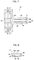
- a tape stopper 21 shown in Fig. 8 is provided insertedly engaged in the stopper guide portion 23.
- the tape stopper 21 is formed from a resin material such as polyacetal as are the tape guide 19 and the T-shaped member 22.
- An operation portion 26 is provided to the tape stopper 21 so as to be exposed when the tape stopper 21 is engaged with the stopper guide portion 23. A user places his/her thumb on the operation portion 26 for sliding the tape stopper 21 along the guide groove 24 in a manner to be described later.
- Grooves 26A are formed to the upper surface of the operation portion 26 for providing extra friction between the user's thumb and the operation portion 26.
- a stopping point SP of the tape stopper 21 corresponds to where a tape T guided by the tape guide 19 abuts the tape stopper 21 (see Fig. 9 (B)).
- Grooves 27 for engaging with the slats 23b are formed in opposites sides (one side shown in Fig. 8, and the other side not shown) of the tape stopper 21.
- a resilient lock arm 29 with a locking protrusion 28 is formed the bottom portion of the tape stopper 21 so as to be encased in the slider guide 23a when the tape stopper 21 is engaged with the stopper guide portion 23.
- the slats 23b are engaged in the grooves 27 and the lock protrusion 28 is resiliently locked in lock grooves 25.
- the stopper 21 can therefore be slid within the guide groove 24 at increments defined by the inter-groove distance of the lock grooves 25.
- Each holder support shaft 31 is formed into a hollow cylindrical shape.
- Coil springs 32 and 33 are inserted in each holder support shaft 31 so as to protrude upward, out of its respective holder support shaft 31.
- a blade receiving stand 34 is provided between the holder support shafts 31 in the upper blade holder support 30.
- the blade receiving stand 34 is constructed in the same manner as described in U.S. Patent 5,271,789 incorporated by reference herein.
- a tape pressing wire 35 is provided in the lower cutter portion 3 so as to span across the tape guide 19. The resilience of the tape pressing wire 35 presses an inserted tape against the blade receiving stand 34.
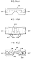
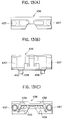
- Figs. 10 (A) through 13 (C) in the present embodiment, four types of upper blade holders 136, 236, 336, and 436 are provided with the tape cutter 1.
- the four types of upper blade holders 35 correspond to the four types of tape (i.e., 9 mm tape, 12 mm tape, 18 mm tape, and 24 mm tape) guidable by the four tape guide grooves 20A through 20D in the tape guide 19.
- All the upper blade holders 136, 236, 336, and 436 have the same basic structure, the only differences being in the shape of upper blades 137, 237, 337, and 437 provided to the interior of respective upper blade holders 136, 236, 336, and 436 and the distance between pairs of positioning members 138, 238, 338, and 438 depending from the lower edge of respective upper blade holders 136, 236, 336, and 436.
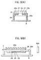
- the upper holder 136 is formed from a resin or alloy such as ABS alloy into a substantially right-angled parallelepiped shape.
- a pair of support holes 137 are formed partially through opposite ends of the upper blade holder 136 so as to be closed off at their upper ends as shown in the cross-sectional side view of Fig. 9 (B).
- Each support hole 137 is formed with an inner diameter that is larger than the outer diameter of the holder support shafts 31. Therefore each holder support shafts 31 and its coil spring 32 or 33 can be inserted into a corresponding support hole 137 and thereby support the upper blade holder 136.
- a pair of positioning members 138 are provided depending from the lower edge of the upper blade holder 136 so that the positioning members are separated by a distance corresponding to the width of a 9 mm tape.
- an upper blade fixing portion 139 is formed to the interior of the upper blade holder 136 as shown in Fig. 10 (C).
- An upper blade 140 is provided in a curved shape to the interior of the upper blade fixing portion 139. The upper blade 140 works cooperatively with the blade receiving stand 34 in order to half cut a 9 mm tape that is between the upper blade 140 and the blade receiving stand 34 and between the pair of positioning members 138.
- Half cutting a tape made from a base tape, an adhesive layer, and a peel-off paper means to cut through the base tape and the adhesive layer but not through the peel-off paper.
- the upper blade 140 is formed with a predetermined curved shape at portions thereof corresponding to the edges of an inserted tape. Therefore, a tape half-cut by the upper blade 140 will therefore have the corners of its base tape and adhesive layer cut into a predetermined curve corresponding to the curve of the upper blade 140.
- the upper blade holder 236 When compared to the upper blade holder 136 for cutting a 9 mm tape, the upper blade holder 236 has basically the same structure except for two differences. As shown in Fig. 11 (B), the first difference is that positioning members 238 are provided to the blade holder 236 separated by a distance corresponding to the width of a 12 mm wide tape. As shown in Fig. 11 (C), the second difference lies in the upper blade 240, for half cutting a 12 mm tape, provided to the interior of the blade holder 236. The upper blade 240 is curved to correspond to a 12 mm tape.
- the upper blade holder 336 with the upper blade 340 provided to its interior for half cutting a 18 mm tape when compared to the upper blade holder 136 for cutting a 9 mm tape and the upper blade holder 236 for cutting a 12 mm tape, has basically the same structure except for two differences.
- the first difference is that the positioning members 338 are separated by a distance corresponding to the width of a 18 mm wide tape.
- the second difference is that the upper blade 340, provided to the interior of the upper blade fixing portion 339 for half cutting an 18 mm tape, is curved to correspond to a 18 mm tape.
- the upper blade holder 436 with an upper blade 440 for half cutting a 24 mm tape fixed to its interior when compared to the upper blade holder 136 for cutting a 9 mm tape, the upper blade holder 236 for cutting a 12 mm tape, and the upper blade holder 336 for cutting a 18 mm tape, has basically the same structure except for two differences.
- the first difference is that the positioning members 438 are separated by a distance corresponding to the width of a 24 mm wide tape.
- the second difference is that the upper blade 440, provided to the interior of the upper blade fixing portion 439 for half cutting an 24 mm tape, is curved to correspond to a 24 mm tape.
- the upper holder 136 is selected. It should be noted that the four types of upper blade holders 136, 236, 336, and 436 are interchangeable. Therefore, the following procedures can be applied to any of the upper blade holders. That is, when a 12 mm tape to be cut, the upper blade holder 236 selected and the following procedures followed accordingly. Similarly, the upper blade holder 336 would have been selected for an 18 mm tape, and the upper blade holder 436 would have been selected for cutting a 24 mm tape.
- the holder support shafts 31 in the upper holder support 30, and the coil springs 132 and 133 positioned to the interior of the holder support shafts 31, are inserted into the support holes 137 of the upper blade holder 136. From this, the upper blade holder 136 is supported by the coil springs 32 and 33 and the holder support shafts 31.
- the tape stopper 21 is slid in the guide groove 24 to an optional desired position.
- the lock protrusion 28 of the resilient lock arm 29 locks in a lock groove 25 of the stopper guide portion 23, thereby locking the tape stopper 21 in the desired position.
- the maximum tape margin is limited in the present embodiment to where the tape stopper 21 abuts the holder support shaft 52A.
- a 9 mm tape to be cut is inserted through the tape guide groove 20A, with a width corresponding to the 18 mm tape, of the tape guide portion 20 formed in the tape guide 19.
- the tape guide groove 20A guides the tape into the tape cutter 1 toward the depending pair of positioning members 138 at the lower edge of the upper blade holder 136.
- the tape is further inserted through the positioning members 138.
- the tape is unidirectionally guided by the tape guide groove 20A and the positioning members 138 until its edge abuts the tape stopper 21.
- the positioning members 138 unidirectionally guide a 9 mm tape inserted into the tape cutter 1 so that the inserted 9 mm tape does not shift in its widthwise direction when the tape is inserted through both of the members 138.
- a 9 mm tape will be unidirectionally guided until it abuts the stopper point SP of the tape stopper 21.
- the tape positioning members 138 thereby guide the tape to the tape stopper 21 without the tape shifting in its widthwise direction. By this, the tape is set at a predetermined half-cut position.
- the pressing portion 5 of the upper cutter portion 2 is pressed down and the upper cutter portion 2 is rotated around the axes 4.
- the rotation of the upper cutter portion 2 presses the lower surface of the metal plate 6 against the upper blade holder 136.
- the upper blade holder 136 is therefore pressed downward against the urging of the coil springs 32 and 33.
- the upper blade 140 provided to the interior of the upper blade holder 136 in cooperation with the blade receiving stand 34, cuts through the base tape and the adhesive layer of the tape so that only the peel-off sheet remains uncut.
- the tape is half cut into a predetermined shape according to the curve of the upper blade 140 provided to the interior of the upper blade holder 136.
- the tape is then withdrawn from the tape cutter 1.
- the uncut end is inserted into the tape cutter 1 and half cut in the same manner.
- the four corners of the tape, two at each end of the tape are half cut to the predetermined shape by the upper blade 40 and the blade receiving stand 34. This concludes the process for half cutting the tape.
- each pair of support holes 237, 337, and 437 of each of the three upper blade holders 236, 336, and 436 is mounted onto a pair of holder support shafts 51A, 51B, 52A, 52B, 53A, and 53B provided to the lower cutter portion 3 by inserting the holder support shafts 51A, 51B, 52A, 52B, 53A, and 53B into the support holes 237, 337, and 437.
- the three upper blade holders 236, 336, and 436 become housed in the lower cutter portion 3.
- the positioning member 238, 338, and 438 pass a predetermined distance downward through corresponding escape hole 15.
- the lock claw R1, provided to the upper cutter portion 2, and the lock groove R2, formed in the lower cutter portion 3, are then resiliently lock together. Because all four of the upper blade holders 136, 236, 336, or 436 (which are separated units from the tape cutter 1) are housed in the tape cutter 1 when the tape butter is not being used, there is no possibility of the upper blade holders 136, 236, 336, or 436 being lost.
- marks can be provided to the tape guide 19 to show the distance to the tape cutting area (i.e., the position where the upper blade 140, 240, 340, or 440 and the blade receiving stand 34 will half cut an inserted tape).
- a mark M1 and a mark M2 are provided to the tape guide 19.
- Mark M1 indicates the position 15 mm from the tape cutting area and mark M2 indicates the position 20 mm from the tape cutting area.
- Marks M1 and M2 make the tape cutter more convenient for users. Marks M1 and M2 can be formed by printing, engraving, or other method.
- an indicator mark M3 and a gauge M4 can be formed in addition to the marks M1 and M2.
- the indication mark M3 is formed on the operation portion 26 of the tape stopper 21.
- the gauge M4 is formed at the side of the stopper guide portion 23 so as to confront the indication mark M3.
- the indicator mark M3 and the gauge M4 together show the distance (tape margin) between the end of a tape abutting the tape stopper 21 and the portion of the tape that will be cut.
- the indicator mark M3 and the gauge M4 allow easy setting of the length of the tape margin when the tape margin is being set with the tape stopper 21. In the example shown in Fig. 15, it can easily be understood that the length of the tape margin is set to 7 mm.
- a tape guide 19 including a plurality of tape guide grooves 20A, 20B, 20C, and 20D for guiding various width tapes is positioned to a lower cutter portion 3.
- pairs of positioning members 138, 238, 338, and 438 depend from respective lower edge of upper blade holders 136, 236, 336, or 436.
- Positioning members 138, 238, 338, and 438 of each pair are separated by a distance which matches the width of a corresponding tape to be cut.
- the upper blade holders 136, 236, 336, or 436 are supported at their support holes 137, 237, 337, or 437 on a pair of holder support shafts 31 formed in the upper blade holder support 30 of the T-shaped member 22, and coil springs 32 and 33 positioned to the interior of the holder support shafts 31, by the holder support shafts 31 and the coil springs 32 and 33 being inserted into respective support holes 137, 237, 337, or 437. Because a tape is inserted into the tape cutter 1 as guided cooperatively by the corresponding tape guide groove 20A through 20D and respective positioning members 138, 238, 338, or 438, the tape is unidirectionally guided and prevented from shifting in the widthwise direction during insertion.
- the tape can be inserted into the tape cutter 1 without shifting in the widthwise direction even when a great distance separates the tape guide 19 and the tape stopper 21. That is, an inserted tape is accurately brought into a predetermined posture relative to the blade receiving stand 34, and consequently the upper blade 140, 240, 340, or 440 (whichever is mounted on the shafts 31), at the cutting area. As a result, ends of a tape can be cut to a predetermined shape according to the curved condition of the upper blade 140, 240, 340, or 440 of the blade holder supported at the tape cutting area.
- a tape stopper 21 can be slid following a guide groove 24 of the slider guide portion 24, and because a lock protrusion 28 of a resilient lock arm 29 formed in the tape stopper 21 can lock the tape stopper 21 in an optional position by engaging with grooves 25 formed in a stopper guide portion 23, the distance (tape margin) between the edge of the tape and the position where the tape will be but can be freely changed and set. Further, by providing the tape cutter 1 with marks M1 and M2 and an indication mark M3 and a gauge M4 as shown in Fig. 15, a desired tape margin can be accurately set when setting the length of the tape margin using the tape stopper 21.
- the tape cutter 1 when the tape cutter 1 is not in use, because one of the upper blade holders 136, 236, 336, and 436 is supported by the support shafts 31 and the coil springs 32 and 33, and because the remaining three of the upper blade holders 136, 236, 336, and 436 are supported by the three pairs of holder support shafts 51A, 51B, 52A, 52B, 53A, and 53B, the upper holders 136, 236, 336, and 436 need not be stored separately from the tape cutter 1 and therefore there is no fear of losing any of the upper blade holders 136, 236, 336, and 436. Also, the upper cutter portion 2 and the lower cutter portion 3 can be locked together by the lock claw R1 of the upper cutter portion 2 and the lock groove R2 of the lower cutter portion 3. Because of this, the tape cutter 1 becomes compact.
- the tape was described as being half-cut by cooperative action between the upper blade 40 and the blade receiving stand 34 in the above-described embodiment, the tape cutter could be structured to completely cut the tape.
- the present invention as described above provides a tape cutter that can accurately and precisely cut both ends of a variety of tapes having different widths to a predetermined shape. Also, the tape cutter can cut tapes an optional position from an end of the tape. Further, the plurality of upper blade holders provided for the different width tapes can be stored housed in the tape cutter.
Landscapes
- Engineering & Computer Science (AREA)
- Mechanical Engineering (AREA)
- Life Sciences & Earth Sciences (AREA)
- Forests & Forestry (AREA)
- Adhesive Tape Dispensing Devices (AREA)
- Printers Characterized By Their Purpose (AREA)
- Handling Of Sheets (AREA)
Applications Claiming Priority (2)
| Application Number | Priority Date | Filing Date | Title |
|---|---|---|---|
| JP5177400A JPH079717A (ja) | 1993-06-23 | 1993-06-23 | テープカッタ装置 |
| JP177400/93 | 1993-06-23 |
Publications (1)
| Publication Number | Publication Date |
|---|---|
| EP0636562A1 true EP0636562A1 (fr) | 1995-02-01 |
Family
ID=16030271
Family Applications (1)
| Application Number | Title | Priority Date | Filing Date |
|---|---|---|---|
| EP94109579A Withdrawn EP0636562A1 (fr) | 1993-06-23 | 1994-06-21 | Dispositif pour couper du ruban |
Country Status (2)
| Country | Link |
|---|---|
| EP (1) | EP0636562A1 (fr) |
| JP (1) | JPH079717A (fr) |
Cited By (4)
| Publication number | Priority date | Publication date | Assignee | Title |
|---|---|---|---|---|
| EP0714741A3 (fr) * | 1994-12-02 | 1997-01-29 | Seiko Epson Corp | Dispositif pour la coupe de l'extrémité d'une bande |
| EP0734818A3 (fr) * | 1995-03-31 | 1997-04-23 | Seiko Epson Corp | Dispositif de coupe, méthode pour sa fabrication et dispositif pour donner une forme et couper l'extrémité d'une bande |
| EP0828056A1 (fr) * | 1996-09-09 | 1998-03-11 | Allpac International B.V. | Dispositif de coupe pour de lamelle |
| US20150076278A1 (en) * | 2013-09-17 | 2015-03-19 | Brother Kogyo Kabushiki Kaisha | Tape Printer |
Citations (10)
| Publication number | Priority date | Publication date | Assignee | Title |
|---|---|---|---|---|
| US3091318A (en) * | 1960-11-30 | 1963-05-28 | Dymo Industries Inc | Cutting and punching attachment for embossing tool |
| US3176572A (en) * | 1962-10-05 | 1965-04-06 | Ralph L Comet | Tape cutting and dispensing device |
| US3237494A (en) * | 1963-07-09 | 1966-03-01 | Dashew Business Machines Inc | Tape cutoff with tab forming means |
| FR2000103A1 (fr) * | 1968-01-10 | 1969-08-29 | Minnesota Mining & Mfg | |
| DE1577688A1 (de) * | 1965-03-01 | 1969-09-18 | Dymo Industries Inc | Praegegeraet |
| DE1604495A1 (de) * | 1965-05-28 | 1971-04-01 | Dymo Industries Inc | Praegegeraet zum Praegen von Baendern unterschiedlicher Breite |
| DE1652468A1 (de) * | 1968-01-31 | 1971-04-15 | Vito West Ag | Praegevorrichtung |
| DE8906227U1 (de) * | 1989-05-19 | 1989-07-20 | Brause GmbH, 8070 Ingolstadt | Schriftgutlocher mit Anschlagschiene |
| EP0449461A2 (fr) * | 1990-03-28 | 1991-10-02 | Brother Kogyo Kabushiki Kaisha | Dispositif de coupe finale pour imprimante de bande |
| US5271789A (en) * | 1990-09-12 | 1993-12-21 | Brother Kogyo Kabushiki Kaisha | Tape end processing unit |
-
1993
- 1993-06-23 JP JP5177400A patent/JPH079717A/ja active Pending
-
1994
- 1994-06-21 EP EP94109579A patent/EP0636562A1/fr not_active Withdrawn
Patent Citations (10)
| Publication number | Priority date | Publication date | Assignee | Title |
|---|---|---|---|---|
| US3091318A (en) * | 1960-11-30 | 1963-05-28 | Dymo Industries Inc | Cutting and punching attachment for embossing tool |
| US3176572A (en) * | 1962-10-05 | 1965-04-06 | Ralph L Comet | Tape cutting and dispensing device |
| US3237494A (en) * | 1963-07-09 | 1966-03-01 | Dashew Business Machines Inc | Tape cutoff with tab forming means |
| DE1577688A1 (de) * | 1965-03-01 | 1969-09-18 | Dymo Industries Inc | Praegegeraet |
| DE1604495A1 (de) * | 1965-05-28 | 1971-04-01 | Dymo Industries Inc | Praegegeraet zum Praegen von Baendern unterschiedlicher Breite |
| FR2000103A1 (fr) * | 1968-01-10 | 1969-08-29 | Minnesota Mining & Mfg | |
| DE1652468A1 (de) * | 1968-01-31 | 1971-04-15 | Vito West Ag | Praegevorrichtung |
| DE8906227U1 (de) * | 1989-05-19 | 1989-07-20 | Brause GmbH, 8070 Ingolstadt | Schriftgutlocher mit Anschlagschiene |
| EP0449461A2 (fr) * | 1990-03-28 | 1991-10-02 | Brother Kogyo Kabushiki Kaisha | Dispositif de coupe finale pour imprimante de bande |
| US5271789A (en) * | 1990-09-12 | 1993-12-21 | Brother Kogyo Kabushiki Kaisha | Tape end processing unit |
Cited By (6)
| Publication number | Priority date | Publication date | Assignee | Title |
|---|---|---|---|---|
| EP0714741A3 (fr) * | 1994-12-02 | 1997-01-29 | Seiko Epson Corp | Dispositif pour la coupe de l'extrémité d'une bande |
| EP0734818A3 (fr) * | 1995-03-31 | 1997-04-23 | Seiko Epson Corp | Dispositif de coupe, méthode pour sa fabrication et dispositif pour donner une forme et couper l'extrémité d'une bande |
| US6116132A (en) * | 1995-03-31 | 2000-09-12 | Seiko Epson Corporation | Cutter, method of making the same and apparatus for shaping and cutting tape end |
| EP0828056A1 (fr) * | 1996-09-09 | 1998-03-11 | Allpac International B.V. | Dispositif de coupe pour de lamelle |
| US20150076278A1 (en) * | 2013-09-17 | 2015-03-19 | Brother Kogyo Kabushiki Kaisha | Tape Printer |
| US9636932B2 (en) * | 2013-09-17 | 2017-05-02 | Brother Kogyo Kabushiki Kaisha | Tape printer |
Also Published As
| Publication number | Publication date |
|---|---|
| JPH079717A (ja) | 1995-01-13 |
Similar Documents
| Publication | Publication Date | Title |
|---|---|---|
| EP0768152B1 (fr) | Dispositif pour couper du papier | |
| EP1467830B1 (fr) | Massicot | |
| US4974320A (en) | Rotatable utility knife | |
| JPS58160099A (ja) | シ−ト穴開け装置 | |
| MXPA96004691A (en) | Paper trimmer | |
| EP0611721B1 (fr) | Dispositif d'impression de ruban | |
| JP2004330408A (ja) | 裁断機とツールの組合せと、裁断機のブレードアセンブリの位置を変える方法 | |
| EP0636562A1 (fr) | Dispositif pour couper du ruban | |
| EP0083152B2 (fr) | Appareil pour montage de diapositives | |
| US20030037657A1 (en) | Puncher for decorative sheet | |
| EP4324607A2 (fr) | Couteau universel avec structure de rupture de bande | |
| US2624116A (en) | Cutter holder | |
| US20090094842A1 (en) | Device for Opening Envelopes | |
| US20020162228A1 (en) | Paper cutter | |
| JPH0544957Y2 (fr) | ||
| JP4377661B2 (ja) | ミクロトーム刀のホルダ装置 | |
| US20080060567A1 (en) | Buckle punch | |
| US20060123966A1 (en) | Guide device for cutting work | |
| JPH05155173A (ja) | 用具挿入タイプのバインディング装置に使用するためのカートリッジ・システム | |
| JP2995191B2 (ja) | 調理用スライサー | |
| KR930004338Y1 (ko) | 봉투개봉 겸용 테이프 컷터기 | |
| JP3113953B2 (ja) | 紙截断機 | |
| JP2586683B2 (ja) | テープの切断装置 | |
| KR200181340Y1 (ko) | 사진 절단기 | |
| JPH0756280Y2 (ja) | テープトリミング装置 |
Legal Events
| Date | Code | Title | Description |
|---|---|---|---|
| PUAI | Public reference made under article 153(3) epc to a published international application that has entered the european phase |
Free format text: ORIGINAL CODE: 0009012 |
|
| AK | Designated contracting states |
Kind code of ref document: A1 Designated state(s): BE DE FR GB |
|
| STAA | Information on the status of an ep patent application or granted ep patent |
Free format text: STATUS: THE APPLICATION IS DEEMED TO BE WITHDRAWN |
|
| 18D | Application deemed to be withdrawn |
Effective date: 19950802 |