EP0636596A1 - Procédé et dispositif pour la production de corps fritté céramique - Google Patents
Procédé et dispositif pour la production de corps fritté céramique Download PDFInfo
- Publication number
- EP0636596A1 EP0636596A1 EP94111394A EP94111394A EP0636596A1 EP 0636596 A1 EP0636596 A1 EP 0636596A1 EP 94111394 A EP94111394 A EP 94111394A EP 94111394 A EP94111394 A EP 94111394A EP 0636596 A1 EP0636596 A1 EP 0636596A1
- Authority
- EP
- European Patent Office
- Prior art keywords
- slurry
- powders
- sintered body
- ceramic sintered
- mixing
- Prior art date
- Legal status (The legal status is an assumption and is not a legal conclusion. Google has not performed a legal analysis and makes no representation as to the accuracy of the status listed.)
- Granted
Links
- 239000000919 ceramic Substances 0.000 title claims abstract description 40
- 238000000034 method Methods 0.000 title claims abstract description 16
- 230000008569 process Effects 0.000 title claims abstract description 12
- 239000002002 slurry Substances 0.000 claims abstract description 222
- 239000000843 powder Substances 0.000 claims abstract description 190
- 238000002156 mixing Methods 0.000 claims abstract description 117
- 239000002245 particle Substances 0.000 claims abstract description 75
- XLYOFNOQVPJJNP-UHFFFAOYSA-N water Substances O XLYOFNOQVPJJNP-UHFFFAOYSA-N 0.000 claims abstract description 50
- 239000000203 mixture Substances 0.000 claims abstract description 28
- 238000005245 sintering Methods 0.000 claims abstract description 25
- 238000000227 grinding Methods 0.000 claims abstract description 22
- 230000008602 contraction Effects 0.000 claims abstract description 16
- 238000005189 flocculation Methods 0.000 claims abstract description 16
- 230000016615 flocculation Effects 0.000 claims abstract description 16
- 239000002904 solvent Substances 0.000 claims abstract description 11
- 238000003756 stirring Methods 0.000 claims abstract description 10
- 239000000356 contaminant Substances 0.000 claims description 25
- 229910052581 Si3N4 Inorganic materials 0.000 claims description 24
- HQVNEWCFYHHQES-UHFFFAOYSA-N silicon nitride Chemical group N12[Si]34N5[Si]62N3[Si]51N64 HQVNEWCFYHHQES-UHFFFAOYSA-N 0.000 claims description 24
- 238000000465 moulding Methods 0.000 claims description 23
- MCMNRKCIXSYSNV-UHFFFAOYSA-N Zirconium dioxide Chemical compound O=[Zr]=O MCMNRKCIXSYSNV-UHFFFAOYSA-N 0.000 claims description 20
- HBMJWWWQQXIZIP-UHFFFAOYSA-N silicon carbide Chemical compound [Si+]#[C-] HBMJWWWQQXIZIP-UHFFFAOYSA-N 0.000 claims description 8
- 229910010271 silicon carbide Inorganic materials 0.000 claims description 8
- 229910052582 BN Inorganic materials 0.000 claims description 5
- PZNSFCLAULLKQX-UHFFFAOYSA-N Boron nitride Chemical compound N#B PZNSFCLAULLKQX-UHFFFAOYSA-N 0.000 claims description 5
- 238000001816 cooling Methods 0.000 claims description 4
- 238000004519 manufacturing process Methods 0.000 abstract description 6
- 239000011369 resultant mixture Substances 0.000 abstract description 3
- 239000000523 sample Substances 0.000 description 38
- QGZKDVFQNNGYKY-UHFFFAOYSA-N Ammonia Chemical compound N QGZKDVFQNNGYKY-UHFFFAOYSA-N 0.000 description 30
- 238000005342 ion exchange Methods 0.000 description 22
- 238000013001 point bending Methods 0.000 description 21
- 239000012535 impurity Substances 0.000 description 17
- 230000000052 comparative effect Effects 0.000 description 16
- 229910021529 ammonia Inorganic materials 0.000 description 15
- 239000006185 dispersion Substances 0.000 description 15
- 239000011230 binding agent Substances 0.000 description 13
- 238000011109 contamination Methods 0.000 description 13
- 239000011164 primary particle Substances 0.000 description 13
- 238000009826 distribution Methods 0.000 description 11
- 230000015572 biosynthetic process Effects 0.000 description 9
- 238000012856 packing Methods 0.000 description 9
- PNEYBMLMFCGWSK-UHFFFAOYSA-N aluminium oxide Inorganic materials [O-2].[O-2].[O-2].[Al+3].[Al+3] PNEYBMLMFCGWSK-UHFFFAOYSA-N 0.000 description 8
- 238000005266 casting Methods 0.000 description 7
- 239000011362 coarse particle Substances 0.000 description 7
- 230000002035 prolonged effect Effects 0.000 description 7
- 229910001220 stainless steel Inorganic materials 0.000 description 7
- 239000010935 stainless steel Substances 0.000 description 7
- 229910000831 Steel Inorganic materials 0.000 description 6
- 238000001935 peptisation Methods 0.000 description 6
- 239000007787 solid Substances 0.000 description 6
- 239000010959 steel Substances 0.000 description 6
- 229910052593 corundum Inorganic materials 0.000 description 5
- 238000001035 drying Methods 0.000 description 5
- 239000000463 material Substances 0.000 description 5
- 239000011812 mixed powder Substances 0.000 description 5
- 229910001845 yogo sapphire Inorganic materials 0.000 description 5
- 229920005822 acrylic binder Polymers 0.000 description 4
- 239000003795 chemical substances by application Substances 0.000 description 4
- 238000005259 measurement Methods 0.000 description 4
- 230000002950 deficient Effects 0.000 description 3
- 230000000694 effects Effects 0.000 description 3
- 239000011148 porous material Substances 0.000 description 3
- 238000012805 post-processing Methods 0.000 description 3
- IJGRMHOSHXDMSA-UHFFFAOYSA-N Atomic nitrogen Chemical compound N#N IJGRMHOSHXDMSA-UHFFFAOYSA-N 0.000 description 2
- 239000004677 Nylon Substances 0.000 description 2
- VYPSYNLAJGMNEJ-UHFFFAOYSA-N Silicium dioxide Chemical compound O=[Si]=O VYPSYNLAJGMNEJ-UHFFFAOYSA-N 0.000 description 2
- 239000012298 atmosphere Substances 0.000 description 2
- 230000008859 change Effects 0.000 description 2
- 238000006243 chemical reaction Methods 0.000 description 2
- 238000002485 combustion reaction Methods 0.000 description 2
- 238000007796 conventional method Methods 0.000 description 2
- 239000000498 cooling water Substances 0.000 description 2
- 230000018044 dehydration Effects 0.000 description 2
- 238000006297 dehydration reaction Methods 0.000 description 2
- 229910001873 dinitrogen Inorganic materials 0.000 description 2
- 230000006872 improvement Effects 0.000 description 2
- 229910052751 metal Inorganic materials 0.000 description 2
- 229920001778 nylon Polymers 0.000 description 2
- 239000004014 plasticizer Substances 0.000 description 2
- 238000003825 pressing Methods 0.000 description 2
- 238000010298 pulverizing process Methods 0.000 description 2
- 230000035939 shock Effects 0.000 description 2
- 238000012360 testing method Methods 0.000 description 2
- 229910000859 α-Fe Inorganic materials 0.000 description 2
- LFQSCWFLJHTTHZ-UHFFFAOYSA-N Ethanol Chemical compound CCO LFQSCWFLJHTTHZ-UHFFFAOYSA-N 0.000 description 1
- 229910026161 MgAl2O4 Inorganic materials 0.000 description 1
- 239000000654 additive Substances 0.000 description 1
- 238000013459 approach Methods 0.000 description 1
- 239000012300 argon atmosphere Substances 0.000 description 1
- QVGXLLKOCUKJST-UHFFFAOYSA-N atomic oxygen Chemical compound [O] QVGXLLKOCUKJST-UHFFFAOYSA-N 0.000 description 1
- 238000005452 bending Methods 0.000 description 1
- 229910052681 coesite Inorganic materials 0.000 description 1
- 230000008878 coupling Effects 0.000 description 1
- 238000010168 coupling process Methods 0.000 description 1
- 238000005859 coupling reaction Methods 0.000 description 1
- 229910052906 cristobalite Inorganic materials 0.000 description 1
- 238000005520 cutting process Methods 0.000 description 1
- 230000007547 defect Effects 0.000 description 1
- 230000006866 deterioration Effects 0.000 description 1
- 230000002542 deteriorative effect Effects 0.000 description 1
- 229910003460 diamond Inorganic materials 0.000 description 1
- 239000010432 diamond Substances 0.000 description 1
- 238000005469 granulation Methods 0.000 description 1
- 230000003179 granulation Effects 0.000 description 1
- 238000002347 injection Methods 0.000 description 1
- 239000007924 injection Substances 0.000 description 1
- 238000001746 injection moulding Methods 0.000 description 1
- 239000007769 metal material Substances 0.000 description 1
- 239000011268 mixed slurry Substances 0.000 description 1
- 229910003465 moissanite Inorganic materials 0.000 description 1
- 239000003960 organic solvent Substances 0.000 description 1
- 239000001301 oxygen Substances 0.000 description 1
- 229910052760 oxygen Inorganic materials 0.000 description 1
- 238000004663 powder metallurgy Methods 0.000 description 1
- 230000009467 reduction Effects 0.000 description 1
- 238000005096 rolling process Methods 0.000 description 1
- 238000005201 scrubbing Methods 0.000 description 1
- 238000010008 shearing Methods 0.000 description 1
- 239000000377 silicon dioxide Substances 0.000 description 1
- 235000012239 silicon dioxide Nutrition 0.000 description 1
- 229910052596 spinel Inorganic materials 0.000 description 1
- 238000001694 spray drying Methods 0.000 description 1
- 230000003068 static effect Effects 0.000 description 1
- 229910052682 stishovite Inorganic materials 0.000 description 1
- 229910052905 tridymite Inorganic materials 0.000 description 1
Images
Classifications
-
- C—CHEMISTRY; METALLURGY
- C04—CEMENTS; CONCRETE; ARTIFICIAL STONE; CERAMICS; REFRACTORIES
- C04B—LIME, MAGNESIA; SLAG; CEMENTS; COMPOSITIONS THEREOF, e.g. MORTARS, CONCRETE OR LIKE BUILDING MATERIALS; ARTIFICIAL STONE; CERAMICS; REFRACTORIES; TREATMENT OF NATURAL STONE
- C04B35/00—Shaped ceramic products characterised by their composition; Ceramics compositions; Processing powders of inorganic compounds preparatory to the manufacturing of ceramic products
- C04B35/515—Shaped ceramic products characterised by their composition; Ceramics compositions; Processing powders of inorganic compounds preparatory to the manufacturing of ceramic products based on non-oxide ceramics
- C04B35/56—Shaped ceramic products characterised by their composition; Ceramics compositions; Processing powders of inorganic compounds preparatory to the manufacturing of ceramic products based on non-oxide ceramics based on carbides or oxycarbides
- C04B35/565—Shaped ceramic products characterised by their composition; Ceramics compositions; Processing powders of inorganic compounds preparatory to the manufacturing of ceramic products based on non-oxide ceramics based on carbides or oxycarbides based on silicon carbide
-
- B—PERFORMING OPERATIONS; TRANSPORTING
- B01—PHYSICAL OR CHEMICAL PROCESSES OR APPARATUS IN GENERAL
- B01F—MIXING, e.g. DISSOLVING, EMULSIFYING OR DISPERSING
- B01F27/00—Mixers with rotary stirring devices in fixed receptacles; Kneaders
- B01F27/05—Stirrers
- B01F27/051—Stirrers characterised by their elements, materials or mechanical properties
- B01F27/053—Stirrers characterised by their elements, materials or mechanical properties characterised by their materials
-
- C—CHEMISTRY; METALLURGY
- C04—CEMENTS; CONCRETE; ARTIFICIAL STONE; CERAMICS; REFRACTORIES
- C04B—LIME, MAGNESIA; SLAG; CEMENTS; COMPOSITIONS THEREOF, e.g. MORTARS, CONCRETE OR LIKE BUILDING MATERIALS; ARTIFICIAL STONE; CERAMICS; REFRACTORIES; TREATMENT OF NATURAL STONE
- C04B35/00—Shaped ceramic products characterised by their composition; Ceramics compositions; Processing powders of inorganic compounds preparatory to the manufacturing of ceramic products
- C04B35/515—Shaped ceramic products characterised by their composition; Ceramics compositions; Processing powders of inorganic compounds preparatory to the manufacturing of ceramic products based on non-oxide ceramics
- C04B35/58—Shaped ceramic products characterised by their composition; Ceramics compositions; Processing powders of inorganic compounds preparatory to the manufacturing of ceramic products based on non-oxide ceramics based on borides, nitrides, i.e. nitrides, oxynitrides, carbonitrides or oxycarbonitrides or silicides
- C04B35/584—Shaped ceramic products characterised by their composition; Ceramics compositions; Processing powders of inorganic compounds preparatory to the manufacturing of ceramic products based on non-oxide ceramics based on borides, nitrides, i.e. nitrides, oxynitrides, carbonitrides or oxycarbonitrides or silicides based on silicon nitride
- C04B35/593—Shaped ceramic products characterised by their composition; Ceramics compositions; Processing powders of inorganic compounds preparatory to the manufacturing of ceramic products based on non-oxide ceramics based on borides, nitrides, i.e. nitrides, oxynitrides, carbonitrides or oxycarbonitrides or silicides based on silicon nitride obtained by pressure sintering
- C04B35/5935—Shaped ceramic products characterised by their composition; Ceramics compositions; Processing powders of inorganic compounds preparatory to the manufacturing of ceramic products based on non-oxide ceramics based on borides, nitrides, i.e. nitrides, oxynitrides, carbonitrides or oxycarbonitrides or silicides based on silicon nitride obtained by pressure sintering obtained by gas pressure sintering
-
- C—CHEMISTRY; METALLURGY
- C04—CEMENTS; CONCRETE; ARTIFICIAL STONE; CERAMICS; REFRACTORIES
- C04B—LIME, MAGNESIA; SLAG; CEMENTS; COMPOSITIONS THEREOF, e.g. MORTARS, CONCRETE OR LIKE BUILDING MATERIALS; ARTIFICIAL STONE; CERAMICS; REFRACTORIES; TREATMENT OF NATURAL STONE
- C04B35/00—Shaped ceramic products characterised by their composition; Ceramics compositions; Processing powders of inorganic compounds preparatory to the manufacturing of ceramic products
- C04B35/622—Forming processes; Processing powders of inorganic compounds preparatory to the manufacturing of ceramic products
- C04B35/626—Preparing or treating the powders individually or as batches ; preparing or treating macroscopic reinforcing agents for ceramic products, e.g. fibres; mechanical aspects section B
Definitions
- This invention relates to a process and a device for producing a ceramic sintered body such as silicon nitride, etc.
- Sintered bodies of ceramics such as silicon nitride, silicon carbide, or alumina, are produced through a process comprising steps of mixing of starting powders, molding, and sintering it by using a powder metallurgy technique.
- sintered bodies of silicon nitride are widely used as materials for cutting tools or structural materials because of their high strength and toughness as well as superior thermal shock resistance and wear resistance.
- ceramic sintered bodies of high quality have been desired that offer an improved strength with less variations in strength as application thereof to parts of an internal combustion engine of a vehicle.
- a grinder such as a ball mill is typically used to mix starting powders.
- Wet mixing is commonly used with a solvent such as alcohol to form a more uniform mixture.
- the slurry obtained as a result of the wet mixing is typically granulated by means of spray drying and is then molded through dry pressing and sintered.
- other available methods used in practice include injection with an addition of a large amount of plasticizer to granulated powder and wet molding to mold the slurry simultaneously with dehydration thereof by means of cast molding or the like.
- the mixing method with a conventional grinder such as a ball mill imparts shock, friction, and sharing force to the starting powders by means of falling, colliding or rolling balls, rods, or pebbles in mixing, which causes the flocculation to be deflocculated or destroyed while the starting powders are ground.
- the starting powders are thus progressively dispersed in the solvent.
- pulverisation of the starting powders by grinding is used positively as an approach to improve the strength of the sintered body in producing silicon nitride sintered bodies of high quality with a high strength.
- the imparted energies are, however, expended on motion or friction of a ground medium. This deteriorates the efficiency of mixing of the powders or dispersion thereof into the solvent, which is a primary object of grinding. Accordingly, a long time is inevitably required for mixing.
- grinding of the starting powders in mixing will cause the variation in the particle diameter and the particle size distribution of the powders, depending on the mixing lot or mixing condition.
- This variation is a cause of deterioration or variations in strength and other properties of the final sintered bodies.
- the ground medium may be worn during repeated collision or scrubbing with each other or with a pot.
- the tailings are contaminated in the starting powders as impurities. This contamination amount is increased as the mixing is performed over a prolonged period of time to ensure uniform mixture, deteriorating the quality of the sintered bodies.
- a slurry of high powder content which contains a smaller amount of solvent and has a good fluidity when considering a molding rate in the wet molding of the slurry through, for example, the cast molding.
- a viscosity of the slurry is, however, increased and hence the fluidity thereof is deteriorated as the amount of the solvent is reduced. It may finally be difficult even to form a slurry.
- grinding ability of the grinder has heretofore been improved or the grinding and mixing have been continued for a long time to obtain a slurry of high powder content.
- an object of the present invention is directed to effectively produce a slurry in which powders are dispersed with a high uniformity and a considerably reduced contamination of impurities without variations in the particle diameter and the particle size distribution of the starting powders; and to provide a molded compact having a stable density, from the slurry, thereby providing a ceramic sintered body of high quality which is superior in properties such as strength with less variations in properties by sintering the molded compact.
- a process for producing a ceramic sintered body which comprises: adding 70-45% by volume of water as a solvent to 30-55% by volume in total of ceramic powder and powder of sintering aids; stirring the resulting powder mixture to form a slurry; deflocculating flocculation of powders with substantially no grinding of the powders by means of causing a high-speed shear flow and/or a high-speed contraction flow in the slurry to thereby mix the slurry until the powders are dispersed with the maximum particle diameter equal to or smaller than that of the unmixed starting powders; forming a molded compact from the slurry; and sintering the molded compact to produce a ceramic sintered body.
- the slurry mixing unit may be any one of adequate devices or machines capable of generating the high-speed shear flow and/or the high-speed contraction flow in the slurry.
- a preferable example includes a device provided with a first toothed comb-shaped member having a plurality of slits and a second toothed comb-shaped member having a plurality of slits and oppositely arranged with a gap of 0.1-5 mm to the first toothed comb-shaped member, the first toothed comb-shaped member and the second toothed comb-shaped member being relatively moved at a high speed such as reciprocated in a linear direction or rotated.
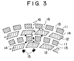
- toothed comb-shaped member is used to represent a comb-shaped member having teeth which are aligned with a slit between adjacent teeth so as to form a comb-like shape, as shown in Fig. 3.
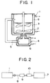
- FIG. 1 is a schematic sectional view showing a mixing through and a slurry mixing unit for use in obtaining a slurry from starting powders, in a device for producing ceramic sintered bodies according to the present invention.
- FIG. 2 is a schematic side view showing a closed line communicated from the mixing trough to a molding machine through a slurry transport pipe, in the device for producing ceramic sintered bodies according to the present invention.
- Fig. 3 is a transversal sectional view showing diagrammatically first and second toothed comb-shaped members which are essentials of the slurry mixing unit according to the present invention.
- dispersibility of the powders is improved by means of causing a high-speed shear flow and/or a high-speed contraction flow in the slurry formed of water and the starting powder (which may contain a sintering aid) with the water as a solvent to deflocculate flocculation of the powder using flow of the slurry itself, causing substantially no grinding of the starting powder rather than by means of the conventional grind mixing with a grinder such as a ball mill.
- a static repulsion can be developed effectively on the surface of the powder by means of using, as a solvent, water having a strong polarity, which contributes to further improvement of the dispersion of the powder.
- no explosion-proof measure is required that is necessary when a flammable organic solvent is used. Accordingly, it is possible to reduce plant costs.
- a powder content of the slurry is as follows: 70-45% by volume of water relative to 30-55% by volume in total of ceramic powder and powder of sintering aids. With a powder content in the slurry of higher than 55% by volume, the water is absorbed strongly by a part of powders because the amount of water is too small. As a result, powders are either in a flocculation containing a larger amount of water than required for achieving an equilibrium state or in powders containing insufficient water to go around, forming only a non-uniform slurry or forming no slurry.
- the slurry can be obtained readily but a dehydration period is prolonged in the wet molding because of an excessive amount of water.
- a larger amount of energy is required to evaporate the water during granulation. Accordingly, it is disadvantageous in an industrial concern.
- the present invention is particularly useful for such high powder content slurries.
- the present invention it is necessary for the present invention to control the particle diameter of the starting powders precisely because the flocculation of the powders is only deflocculated in mixing the slurry and no pulverization with grinding of the powders is performed.
- the uniformity of powder packing is deteriorated when the starting powders contain coarse particles.
- the molded compact is thus more likely to have pores and will be a defective with the pores and the coarse particles left in the sintered body, which is a cause of reduction in strength.
- flocculated particles having the maximum particle diameter larger than the above mentioned value may also vary the powder packing structure and cause the sintered body to be a defective reducing the strength thereof if such particles are present in the slurry.
- the flocculated powders are effectively deflocculated without requiring any substantial grinding of the starting powders and it is possible to obtain a slurry in which the particles are dispersed with the maximum particle diameter equal to or smaller than that of the unmixed starting powders, i.e., a slurry containing no flocculated particles having the maximum particle diameter larger than that of the unmixed starting powders.
- a slurry in the particle dispersed state according to the present invention can pass almost freely through a sieve having a sieve opening of not smaller than the maximum particle diameter of the unmixed starting powders.
- the present invention it is possible in the present invention to prepare the slurry in a given dispersion state with good reproducibility by means of controlling the particle diameter of the starting powders.
- the molded compact having a stable density can be obtained from this slurry.
- the starting powders For silicon nitride for example, particles having the particle diameter of larger than 30 ⁇ m in the sintered body serve as defective, so that it is necessary to control the maximum particle diameter of the starting powders to be equal to or smaller than 30 ⁇ m, and preferably equal to or smaller than several ⁇ m.
- an average particle diameter of the starting powders is equal to or smaller than 3 ⁇ m, preferably equal to or smaller than 2 ⁇ m.
- the slurry thereof is required to be in such a dispersion state that permits to be passed through a sieve having a sieve opening of not larger than 30 ⁇ m which corresponds to the maximum particle diameter.
- the starting powders preferably has the average particle diameter and the maximum particle diameter similar to those in the silicon nitride.
- Si3N4 powder silicon nitride (Si3N4) powder is used as a starting powder.
- Si3N4 powder of which particle diameter is controlled, powder of sintering aids, and water, and other additives such as a binder if necessary, are placed in a mixing trough 1 shown in Fig. 1 and are stirred with stirring blades 2 to form a slurry. Formation of the slurry is more difficult with the smaller particle diameter of the powders and the higher powder content.
- the powders are flocculated significantly at that time of slurry formation, so that a resultant slurry 3 is supplied to a slurry mixing unit 4 disposed in a slurry circulation conduit 5 coupled to the mixing trough 1 to cause a high-speed shear flow and/or a high-speed contraction flow in the slurry 3.
- the flocculation of the powders is deflocculated in the slurry mixing unit 4 and mixed to the dispersion state with no flocculated particles. However, substantially no grinding of the starting powders is caused therein.
- the mixed slurry is returned to the mixing trough 1 through the slurry circulation conduit 5 and is again supplied to the slurry mixing unit 4, which is continued repeatedly.
- the slurry mixing unit 4 may be disposed in the mixing trough 1 as a part of the mixing trough 1.
- a temperature of the slurry 3 at 40°C or lower, and preferably at 35°C or lower by means of providing a water cooling jackets 6 in the mixing trough 1 and the slurry mixing unit 4 to circulate cooling water.
- the slurry at a temperature of higher than 40°C is degenerated, increasing the possibility of adhesion thereof to the mixing trough 1 or of clogging caused in the slurry circulation conduit 5.
- the moldability is deteriorated. While the cause of this is unclear, it may be considered that the reaction between the Si3N4 powder and water proceeds due to an increasing temperature, and the degenerated surface reacts with the binder added or the binder is degenerated.
- increase in an oxygen content as a result of reaction with water varies the sinterability, which will be a cause of variations in density of the sintered bodies.
- the slurry so obtained may be formed into a molded compact in an ordinary manner, for example, by granulating, and then dry pressing or injection molding with an addition of a large amount of plasticisers to the granulated powder.
- wet molding such as casting molding to mold the slurry simultaneously with removing water therefrom.
- a closed line is provided between the mixing and molding stages, where impurities are most likely to be contaminated, by means of coupling the mixing trough 1 with a molding machine 7 through a slurry transport pipe 8. This permits to avoid readily contamination by the impurities and pollution from the production environment.
- foreign matters or impurities introduced in the mixing trough 1 or the slurry mixing unit 4 can be removed by incorporating a magnetic processor 9 and a contaminant filter 10 for removing foreign matters in the course of the slurry transport pipe 8.
- the production device of the type described permits production of the sintered body having excellent properties such as the strength with a minimized the amount of contaminants.
- a preferred embodiment of the slurry mixing unit for use in causing the high-speed shear flow and/or the high-speed contraction flow in the slurry comprises, as diagrammatically shown in transversal section of essentials in Fig. 3, two pairs of first toothed comb-shaped member 11 having a plurality of slits and arranged on a circumference and second toothed comb-shaped member 12 having a plurality of slits and arranged oppositely on another circumference with being away from the first toothed comb-shaped member 11 inwardly at a gap 14 of 0.1-5 mm.
- the second toothed comb-shaped member 12 rotates at a high speed on the circumference relative to the fixed first toothed comb-shaped member 11.
- the slurry supplied to the center of the first and second toothed comb-shaped members 11 and 12 contains a large amount of flocculated coarse particles 15. These flocculated coarse particles 15 are deflocculated by the high-speed contraction flow generated when the slurry is sucked into the gap 14 between the fixed inner first toothed comb-shaped member 11 and the inner second toothed comb-shaped member 12, which is rotated at a high speed, through slits 3 of the latter member.
- the high-speed shear flow is generated in the slurry introduced in the gap 14 between the fixed first toothed comb-shaped member 11 and the second toothed comb-shaped member 12 rotated at a high speed. It is then discharged out of the inner first toothed comb-shaped member 11 through the slit as the deflocculation of the flocculated particles proceeds.
- the slurry discharged out of the slit 13 of the outer fixed first toothed comb-shaped member 11 is a slurry in which the starting powders is dispersed almost in the form of primary particles 16 and the flocculation is almost completely deflocculated. Similar effects can be obtained other than the specific example in Fig.
- a gap 14 between the first toothed comb-shaped member and the second toothed comb-shaped member is in a range of 0.1-5 mm.
- the gap is smaller than 0.1 mm, the flocculated coarse particles tend to be caught.
- a gap of larger than 5 mm interferes effective deflocculation effects on the flocculated particles because the shearing force generated by the high-speed shear flow becomes small.
- a width of the slit in the first and second toothed comb-shaped members is 0.1 mm or larger in order to prevent the flocculated coarse particles from being caught.
- it is desirable that at least one of the toothed comb-shaped members has a slit width of not more than 10 mm because a slit width exceeding 10 mm lowers the deflocculation effects due to the contraction flow.
- the first toothed comb-shaped member and the second toothed comb-shaped member are formed of any one of wear resistant ceramics such as silicon nitride, zirconia, silicon carbide, and cubic boron nitride, or a combination thereof.
- wear resistant ceramics such as silicon nitride, zirconia, silicon carbide, and cubic boron nitride, or a combination thereof.
- These toothed comb-shaped members if made of a metallic material such as stainless steel, are more likely to be worn due to the starting powders in the slurry and, thus, the amount of the contaminants is increased. On the contrary, the amount of the contaminants can be reduced significantly by means of forming them of the wear resistant ceramic(s).
- the wear, resistant ceramic(s) may be used for portions to be contact with the slurry such as the inner wall of the slurry mixing unit or the inner wall of the mixing trough other than the toothed comb-shaped members.
- Y2O3 powder 4.7% by weight of Y2O3 powder, 0.6% by weight of Al2O3 powder, and 3.7% by weight of MgAl2O4 powder were added as sintering aids to 91% by weight of Si3N4 powder to prepare starting powders having an average particle diameter of 0.5 ⁇ m and a maximum particle diameter of 5 ⁇ m as a starting powder mixture.
- the particle diameter of the starting powders was measured for 1 g of the powders having the above mentioned composition by using a laser diffraction particle size distribution meter in which the powders had been dispersed well in 10 cc of an ion exchange water, and then diluted by 1,000 times with an additional ion exchange water.
- the starting powders were placed in the mixing trough 1 of the device shown in Fig. 1, to which an ion exchange water was added such that the powder content became 40% by volume.
- an acrylic binder was added in an amount corresponding to 0.5% by weight of the total amount of powders and then ammonia was added such that pH of a slurry became approximately 9.5.
- the starting powders were mixed with the water to form a slurry by rotating the stirring blades 2 formed of zirconia in the mixing trough 1. The slurry was stirred for 30 minutes.
- the resultant slurry 3 was supplied little by little to the slurry mixing unit 4.
- the powder flocculation were deflocculated by means of causing the high-speed shear flow and the high-speed contraction flow in the slurry 3 in the slurry mixing unit 4. Mixing and deflocculation were repeated while the slurry 3 was circulated between the mixing trough 1 and the slurry mixing unit 4 through the slurry circulation conduit 5.
- the slurry 3 was mixed over different total mixing time of 40 minutes, 1 hour, 3 hours, and 5 hours.
- the slurry mixing unit 4 comprises, as shown in Fig. 3, two pairs of first toothed comb-shaped member 11 of zirconia having a plurality of slits 13 between the adjacent teeth which are arranged on a circumference and second toothed comb-shaped member 12 of zirconia having a plurality of slits between the adjacent teeth which are arranged on another circumference inside the first toothed comb-shaped member 11 at a gap 14 of 2 mm.
- the second toothed comb-shaped members 12 were rotated at 2000 rpm relative to the fixed first toothed comb-shaped members 11.
- a width of the slits 13 between the teeth constituting the respective toothed comb-shaped members were 4 mm and 20 mm for the first toothed comb-shaped member 11 and the second toothed comb-shaped member 12, respectively.
- a temperature of the slurry was controlled at 20-35°C by means of circulating the cooling water through the water cooling jackets 6 of the mixing trough 1 and the slurry mixing unit 4.
- the slurry samples so obtained were taken at a small amount and diluted to the same content as in the above mentioned measurement on the particle diameter of the starting powders to measure the particle diameter of the powders in the slurry.
- a portion of the slurry sample was passed through a nylon sieve (mesh filter) having a sieve opening of 5 ⁇ m to measure a percentage of passing.
- percentage of passing or "passability” is used to mean the proportion (%) of powders which can pass through a sieve relative to the total amount of powders contained in a slurry.
- the slurry was dried and subjected to an element analysis to assess a total amount of metal elements increased after the mixing operation as an amount of contamination by impurities due to the mixing.
- each slurry was casting molded under a pressure of 30 kg/cm2 to produce molded compacts of 100 mm long and wide, and 10 mm thick. Each molded compact was assessed in the density, moldability (time required for molding), and molded state.
- each molded compact was dried and degreased, and was then sintered at 1550°C for 4 hours in a nitrogen gas atmosphere of 1 atm. Subsequently, each compact was subjected to secondary sintering at 1600°C for 1 hour in the nitrogen gas atmosphere of 1000 atm. Bending test pieces of 3 mm x 4 mm x 40 mm were cut out of the resultant sintered bodies according to JIS R1601. The pieces were finished through grinding with a grinding diamond wheel of #800. A four-point bending strength at a room temperature was measured for 15 test pieces for each sample. In addition, Weibull coefficient indicative of the distribution in strength was also obtained.
- an ion exchange water, a binder, and ammonia were added at the same ratio as described above to the starting powders which had been blended at the same ratio as those described above.
- the resultant mixture was mixed by using a ball mill with alumina balls as a grinding medium in which an inner surface of the pot was lined with alumina. Mixing was performed for each mixing time of 40 minutes, 5 hours, 30 hours, 72 hours and 200 hours to form each slurry sample.
- the properties of the resultant slurry sample were measured in the same manner as described above.
- a sintered body was produced using each slurry sample and the strength thereof was measured in the same way.
- Table 1 shows the average and maximum primary particle diameters of powders after mixing and properties of each slurry while Table 2 shows the properties of the molded compact and the sintered body obtained with each slurry sample.
- Table 1 Sample Mixer Mixing time Primary particle diameter of mixed powders Properties of slurry Average ( ⁇ m) Maximum ( ⁇ m) Sieve passability (%) Impurities introduced due to mixing (ppm) 1* Fig.1 40 min. 0.5 5 76 ⁇ 10 2 Fig.1 1 hr. 0.5 5 100 ⁇ 10 3 Fig.1 3 hr. 0.5 5 100 ⁇ 10 4 Fig.1 5 hr.
- the slurry (Samples 2-4) in the dispersion state passable through the sieve having the sieve opening of 5 ⁇ m contains less contaminants, is superior in moldability, and is not fluctuated in density of the molded compact depending the mixing time. Therefore, the resultant sintered bodies have high strength with a minimized variation thereof.
- the comparative examples (Samples 5-9) require a significantly long mixing time to obtain good dispersion state of the slurry.
- the amount of the inclusion of impurities increases extremely with the prolonged mixing time.
- the moldability and the density of the molded compacts are greatly fluctuated depending on the mixing time.
- the resultant sintered bodies are low in strength and the strength is varied widely.
- Example 1 An ion exchange water was added to the starting powders mixture of silicon nitride and sintering aids having the same composition, average particle diameter, and maximum particle diameter as those described in Example 1 such that the powder content became 20, 30, 40, 55, and 60% by volume, respectively.
- the binder and ammonia were added in the same ratio as in Example 1. The mixture was slurried and then mixed over a 5-hour mixing time in the same way as in Example 1, using the device shown in Fig. 1.
- Example 2 molding was performed as in Example 1 by using the resultant slurry samples.
- the resultant molded compacts were assessed in density, moldability (time required for molding), and molded state.
- the results are given in Table 4.
- Table 4 Sample Properties of Molded Compact Density (g/cm3) Moldability (min.) State of molded compact 10* 1.63 15.8 good 11 1.74 4.5 good 12 1.75 3.3 good 13 1.75 2.0 good 14* 1.43 6.0 cavity and crack (NOTE) Samples marked with asterisks (*) in the table are comparative examples.
- "Crack" and "cavity" in the column of the state of the molded compact indicate occurrence of a crack after drying and occurrence of cavity due to insufficient packing, respectively.
- Tables 3 and 4 indicate that defects such as the cavities or the cracks are caused in the resultant molded compact when mixed at a higher powder content than the powder content range according to the present invention because the dispersion state of the powders in the slurry becomes non-uniform due to insufficient amount of solvent as in Sample 14.
- the dispersion state of the slurry and the resultant molded compact are good as in Sample 10.
- the molding time is prolonged due to the larger amount of water to be removed, so that it is not preferable in an industrial viewpoint.
- An ion exchange water was added to the starting powder mixture of silicon nitride and sintering aids having the same composition as in Example 1, an average particle diameter of 1 ⁇ m, and a maximum particle diameter of 15 ⁇ m such that the powder content became 35, 40, 45, 50, and 55% by volume.
- the binder and ammonia were added in the same ratio as in Example 1.
- the mixture was slurred and then mixed over a 5-hour mixing time in the same way as in Example 1, using the device in Fig. 1.
- Example 1 For comparison, the above mentioned Example 1 was repeated to form slurry samples except that the same ball mill as that used in Example 1 for comparison was used in place of the device in Fig. 1 and that the mixing time was 100 hours.
- the average and maximum primary particle diameter after mixing as well as the percentage of passing through the sieve having a sieve opening of 15 ⁇ m, the amount of contaminants, and the viscosity as the properties of the slurry were measured for each resultant slurry as in Example 1. The results are given in Table 5.
- Table 5 Sample Powder content (vol.%) Mixer Primary particle diameter of mixed powders Properties of slurry Ave. ( ⁇ m) Max.
- Example 2 Each resultant slurry sample was assessed in the same manner as in Example 1. As a result, no change was found in average particle diameter and maximum particle diameter in any sample. In addition, these slurry samples were passed through a nylon sieve having a sieve opening of the maximum particle diameter for each sample. All samples exhibited the percentage of passing of 100%.
- each slurry was subjected to molding and sintering in the same manner as in Example 1.
- the four-point bending strength of the resultant sintered body was measured, of which results are given in Table 7.
- Samples 27, 29, and 30 in which the starting powders have a maximum particle diameter of larger than 30 ⁇ m or an average particle diameter of larger than 3 ⁇ m are found that the strength thereof is reduced due to remaining coarse particles or pores, and the variation in strength is wide (Weibull coefficient is small).
- Table 7 Sample 25 26 27 28 29 30 Four-point bending strength (kg/mm2) 153.0 150.4 132.8 140.5 123.0 120.6 Weibull coefficient of four-point bending strength 22.1 21.3 10.8 20.6 14.3 9.5
- Example 9 An ion exchange water was added to the starting powder mixture having the same composition and particle diameter as those in Example 1 such that the powder content became 38% by volume.
- binder was added in an amount corresponding to 0.5% by weight of the total amount of powders.
- ammonia the slurry was adjusted in pH in mixing to the values as set forth in Table 9 and was mixed over 5 hours as in Example 1. During this, change of the slurry with time was observed to measure a time required for apparent slurry formation by stirring. In addition, the viscosity of the slurry after 5-hour mixing was also measured. The results are given in Table 9.
- Samples 34 and 35 having a low pH value require longer time for slurry formation, and the resultant slurry has a high viscosity.
- Sample 38 having a high pH value ammonia was vigorously volatilized from the slurry during mixing.
- the slurry can readily be obtained with Samples 36 and 37 of which pH values were in a range of 8-10, which permits stable mixing resulting in a slurry having a low viscosity and a good dispersibility.
- a slurry was prepared in the same manner as in Example 1, using the device shown in Fig. 1. In this example, it was performed with four different gaps 14 as set forth in Table 10 defined between two pairs of first toothed comb-shaped member 11 and the second toothed comb-shaped member 12 shown in Fig. 3 in the slurry mixing unit 4.
- An inner diameter of the fixed inner first toothed comb-shaped member 11 was 85 mm and an inner diameter of the outer first toothed comb-shaped member 11 was 110 mm.
- the gap 14 was adjusted by means of changing inner and outer diameters of the inner and outer second toothed comb-shaped member 12 to be rotated.
- the composition and particle diameter and powder content of the starting powder mixture and pH and temperature of the slurry were same as those in Example 1.
- the slurry was formed in the mixing trough 1 and the flocculation was deflocculated and mixed in the slurry mixing unit 4 in the same manner as in Example 1. However, the mixing time was 3 hours.
- the viscosity of the resultant slurry was measured.
- an element analysis was made after the slurry was dried to determine a total amount of the increased metal elements, which was assessed as the amount of contaminants. The results are given in Table 10.
- Y2O3 powder 5.5% by weight of Y2O3 powder, and 1.0% by weight of Al2O3 powder were added as sintering aids to 93.5% by weight of ZrO2 powder to prepare a starting powder mixture having an average particle diameter of 0.6 ⁇ m and a maximum particle diameter of 5 ⁇ m.
- the particle diameter of the starting powders was measured for 1 g of the powders having the above mentioned composition using a laser diffraction particle size distribution meter in which the powders had been dispersed well in 10 cc of an ion exchange water, and diluted by 1,000 times with an additional ion exchange water.
- an ion exchange water was added such that the powder content became 40% by volume.
- an acrylic binder was added in amount corresponding to 0.5% by weight of the total amount of powders and then ammonia was added such that pH of a slurry becomes approximately 10.
- a slurry was formed by as in Example 1 and then mixed under conditions of 1 hour, 3 hours, and 5 hours in the same manner as in Example 1.
- an ion exchange water, a binder and ammonia were added in the same ratio to the starting powders blended in the same ratio as those described above by using the same ball mill as that used in Example 1 for comparison in place of the device in Fig. 1. The mixing was performed for 5 hours, 50 hours, and 100 hours.
- the resultant slurry samples were measured for the average and maximum primary particle diameter of the powders after mixing as well as the percentage of passing through a sieve having a sieve opening of 5 ⁇ m, the amount of contaminants, and the viscosity as the properties of the slurry as in Example 1. The results are given in Table 11.
- each slurry sample was casting molded under a pressure of 30 kg/cm2 to produce molded compacts of 100 mm long and wide, and 10 mm thick. Each molded compact was assessed in the density, and molded state. The results are given in Table 11.
- each molded compact was dried and degreased, and was then sintered at 1480°C for 3 hours in vacua. Subsequently, the compact was subjected to secondary sintering at 1350°C for 1 hour in the argon atmosphere of 1000 atm. A four-point bending strength was measured in the same way as in Example 1 and Weibull coefficient indicative of the distribution in strength were also obtained.
- the slurry according to the present invention contains less contaminants, is low in viscosity, and is superior in moldability, permitting formation of the high-density molded compact.
- the sintered bodies obtained therefrom have a high strength with a reduced scattering in the strength.
- Example 1 To the starting powders an ion exchange water was added such that the powder content became 40% by volume.
- an acrylic binder and a polycarboxylic deflocculating agent were added in amounts of 0.5% by weight and 0.5% by weight, respectively, based on the total amount of the powders and then ammonia was added such that pH of a slurry becomes approximately 9.
- a slurry was formed by using the device shown in Fig. 1 as in Example 1 under the same slurry formation conditions as in Example 1 and then mixed under conditions of 1 hour, 3 hours, and 5 hours in the same manner as in Example 1.
- an ion exchange water, a binder, a deflocculating agent and ammonia were added in the same proportions as described above to the starting powders blended in the same ratio as those described above by using the same ball mill as that used in Example 1 for comparison in place of the device in Fig. 1.
- the mixing was performed under conditions of 5 hours, 50 hours, and 100 hours.
- the resultant slurry samples were measured for the average and maximum primary particle diameter of the powders after mixing as well as the percentage of passing through a sieve having a sieve opening of 10 ⁇ m, the amount of contaminants, and the viscosity as the properties of the slurry as in Example 1. The results are given in Table 13.
- each slurry sample was casting molded under a pressure of 30 kg/cm2 to produce molded compacts of 100 mm long and wide, and 10 mm thick. Each molded compact was assessed in the molded state. The results are given in Table 14.
- each molded compact was dried and degreased, and was then sintered at 2000°C for 1 hour in vacua.
- a four-point bending strength was measured in the same way as in Example 1 and Weibull coefficient indicative of the distribution in strength were also obtained.
- the slurry according to the present invention contains less contaminants, is low in viscosity, and is superior in moldability. Accordingly, the sintered bodies obtained from the slurries have a high strength and the strength is less varied.
- Table 14 Sample Properties of molded compact Properties of sintered bodies State of molded compact Four-point bending strength (kg/mm2) Weibull coefficient of four-point bending strength 49 good 81.5 21.8 50 good 85.0 24.5 51 good 84.9 25.2 52* cavity/crack 20.6 4.0 53* crack 45.2 11.8 54* good 58.3 15.1 (NOTE) Samples marked with asterisks (*) in the table are comparative examples. "Crack” and "cavity" in the column of the state of molded compact indicate occurrence of a crack after drying and occurrence of cavity due to insufficient packing, respectively.
- Example 1 To the starting powders, an ion exchange water was added such that the powder content became 40% by volume. In addition, an acrylic binder and a polycarboxylic deflocculating agent were added in an amount of 0.5% by weight for each, based on the total amount of the powders and, then, ammonia was added such that pH of a slurry becomes approximately 9.5.
- a slurry was formed as in Example 1 under the same slurry formation conditions as in Example 1 and, then, mixed under the respective conditions of 1 hour, 3 hours, and 5 hours in the same manner as in Example 1.
- an ion exchange water, a binder, a deflocculating agent and ammonia were added in the above-mentioned ratio to the starting powders blended in the same ratio as those described above by using the same ball mill as that used in Example 1 for comparison in place of the device in FIG. 1.
- the mixing was performed under condition of 5 hours, 50 hours, and 100 hours.
- the resultant slurry samples were measured for the average and maximum primary particle diameters of the powders after mixing as well as the percentage of passing through a sieve having a sieve opening of 5 ⁇ m, the amount of contaminants, and the viscosity as the properties of the slurry, as described in Example 1. The results are given in Table 15.
- each slurry sample was casting molded under a pressure of 30 kg/cm2 to produce molded compacts of 100 mm long and wide, and 10 mm thick. Each molded compact was observed for the molded state. The results are given in Table 16.
- each molded compact was dried and degreased, and was then sintered at 1620°C for 1.5 hours.
- a four-point bending strength was measured in the same way as in Example 1 and Weibull coefficient indicative of the distribution in strength were also obtained.
- the slurry according to the present invention contains less contaminants, is low in viscosity, and is superior in moldability.
- the sintered bodies obtained therefrom have a high strength with a minimized distribution in strength.
- Example 2 An ion exchange water, a binder, and ammonia in the same ratio as in Example 1 were added to the starting powders prepared from silicon nitride and sintering aids having the same composition, average particle diameter, and maximum particle diameter as those in Example 1 to mix them over 5 hours in the same manner as in Example 1 by using the device in FIG. 1 having, in the slurry mixing unit 4, the first and second toothed comb-shaped members 11 and 12 made of each material of silicon nitride, zirconia, silicon carbide, cubic boron nitride, ferrite-based stainless steel, and steel. The amount of contaminants in each of the resultant slurries was measured in the same way as in Example 1.
- each slurry was molded and sintered in the same manner as in Example 1, and the four-point bending strength of each resultant sintered body was measured.
- the measurement results are given in Table 17.
- the material of the toothed comb-shaped members is silicon nitride, zirconia, silicon carbide, or cubic boron nitride, the amount of the contaminants is small, the strength is high, and the variation in strength is insignificant. On the contrary, with stainless steel, in particular, steel, the amount of the contaminants is increased greatly. The strength is low which is widely varied, so that it is not preferable.
- Table 17 Sample Material of toothed comb-shaped members Contamination by impurities (ppm) Properties of Sintered Body Four-point bending strength (kg/mm2) Weibull coefficient of four-point bending strength 61 Silicon nitride ⁇ 10 152.8 22.6 62 Zirconia ⁇ 10 153.9 25.9 63 Silicon carbide 15 150.2 20.0 64 Cubic boron nitride ⁇ 10 153.4 24.6 65 Stainless steel 120 125.8 14.3 66 Steel 410 98.5 9.7
- Example 11 An ion exchange water, a binder, and ammonia in the same ratio as in Example 1 were added to the starting powders of silicon nitride and sintering aids having the same composition, average particle diameter, and maximum particle diameter as those in Example 1 to mix them over 3 hours in the same manner as in Example 1.
- the toothed comb-shaped members used in Example 11 only two cases of toothed comb-shaped members made of ferrite-based stainless steel and steel were used. Thereafter, the pressure casting molding was performed to directly form the molded compact under the same conditions as in Example 1 after passing each slurry through the slurry transport pipe in which the magnetic processor and the contaminant filter shown in FIG. 2 were incorporated.
- Example 18 For comparison, a portion of the slurry before being passed through the slurry transport pipe was used to form a molded compact without post-processing in the same manner as in Example 1. Next, sintered bodies were formed by using each slurry sample in the same manner as in Example 1, and the four-point bending strength of each sintered body was measured. The measurement results are given in Table 18.
- the strength can be improved and the variation in strength can also be improved by performing the post-processing through the slurry transport pipe in which the magnetic processor and the contaminant filter were incorporated.
- Table 18 Sample Material of toothed comb-shaped members Post-processing with slurry transport pipe Properties of sintered body Four-point bending strength (kg/mm2) Weibull coefficient of four-point bending Strength 67 Stainless Steel did 145.6 19.9 68 Stainless Steel didn't 123.8 15.1 69 Steel did 140.5 16.7 70 Steel didn't 96.5 9.0
- the average particle diameter and the maximum particle diameter of the starting powders can be kept intact and the amount of the contaminants is advantageously small. Accordingly, it is possible to effectively obtain a slurry with a highly uniform dispersion of the powders and a superior moldability.
Landscapes
- Chemical & Material Sciences (AREA)
- Engineering & Computer Science (AREA)
- Ceramic Engineering (AREA)
- Manufacturing & Machinery (AREA)
- Materials Engineering (AREA)
- Structural Engineering (AREA)
- Organic Chemistry (AREA)
- Inorganic Chemistry (AREA)
- Chemical Kinetics & Catalysis (AREA)
- Compositions Of Oxide Ceramics (AREA)
- Ceramic Products (AREA)
- Preparation Of Clay, And Manufacture Of Mixtures Containing Clay Or Cement (AREA)
Applications Claiming Priority (6)
| Application Number | Priority Date | Filing Date | Title |
|---|---|---|---|
| JP20282993 | 1993-07-23 | ||
| JP20282993 | 1993-07-23 | ||
| JP202829/93 | 1993-07-23 | ||
| JP15459794 | 1994-07-06 | ||
| JP154597/94 | 1994-07-06 | ||
| JP15459794A JP3154313B2 (ja) | 1993-07-23 | 1994-07-06 | セラミックス焼結体の製造方法及び製造装置 |
Publications (2)
| Publication Number | Publication Date |
|---|---|
| EP0636596A1 true EP0636596A1 (fr) | 1995-02-01 |
| EP0636596B1 EP0636596B1 (fr) | 2000-01-12 |
Family
ID=26482838
Family Applications (1)
| Application Number | Title | Priority Date | Filing Date |
|---|---|---|---|
| EP94111394A Expired - Lifetime EP0636596B1 (fr) | 1993-07-23 | 1994-07-21 | Procédé et dispositif pour la production de corps fritté céramique |
Country Status (4)
| Country | Link |
|---|---|
| US (1) | US5879078A (fr) |
| EP (1) | EP0636596B1 (fr) |
| JP (1) | JP3154313B2 (fr) |
| DE (1) | DE69422554T2 (fr) |
Cited By (3)
| Publication number | Priority date | Publication date | Assignee | Title |
|---|---|---|---|---|
| WO1996035651A1 (fr) * | 1995-05-10 | 1996-11-14 | Saint-Gobain Industrial Ceramics, Inc. | Boues de nitrure de silicium a forte teneur en matiere solide |
| WO2012113672A3 (fr) * | 2011-02-25 | 2013-04-18 | Evonik Degussa Gmbh | Dispositif et procédé pour façonner un matériau à base de sio2 |
| CN112387370A (zh) * | 2020-10-26 | 2021-02-23 | 湖北昌耀新材料股份有限公司 | 一种能提高磷石膏陶粒轻骨料强度的打磨工艺 |
Families Citing this family (8)
| Publication number | Priority date | Publication date | Assignee | Title |
|---|---|---|---|---|
| US5997794A (en) * | 1998-08-18 | 1999-12-07 | Energy Research Corporation | Method of making matrix for carbonate fuel cells |
| US6776954B1 (en) * | 2000-05-31 | 2004-08-17 | Honeywell International Inc. | Recycle methods for water based powder injection molding compounds |
| AU2002212710A1 (en) | 2000-11-27 | 2002-06-03 | K-Tech Devices Corp. | Ceramic resistor and method for manufacture thereof |
| WO2007097004A1 (fr) * | 2006-02-24 | 2007-08-30 | Ibiden Co., Ltd. | Appareil et procede de melangeage a l'etat humide et procede de production de structures en nid d'abeille |
| JP2008127261A (ja) * | 2006-11-22 | 2008-06-05 | Sumitomo Chemical Co Ltd | セラミックス顆粒の製造方法、セラミックス成形体の製造方法およびセラミックス焼結体の製造方法 |
| JP2010037146A (ja) * | 2008-08-05 | 2010-02-18 | Nippon Soken Inc | 分散スラリーの調製方法及び分散スラリー製造装置 |
| US9193105B1 (en) * | 2011-08-31 | 2015-11-24 | Consolidated Nuclear Security, LLC | Casting fine grained, fully dense, strong inorganic materials |
| KR102831854B1 (ko) | 2019-12-19 | 2025-07-10 | 가부시끼가이샤 도꾸야마 | 육방정 질화붕소 분말 및 그의 제조 방법 |
Citations (6)
| Publication number | Priority date | Publication date | Assignee | Title |
|---|---|---|---|---|
| GB774275A (en) * | 1952-03-12 | 1957-05-08 | Peter Willems | Mixing and dispersing device |
| US2945634A (en) * | 1955-05-20 | 1960-07-19 | Henschel Werke Ges Mit Beschra | Machine for mixing and comminuting materials |
| US4126422A (en) * | 1976-04-26 | 1978-11-21 | Corning Glass Works | Method of densifying metal oxides |
| US4243424A (en) * | 1978-11-13 | 1981-01-06 | The Dow Chemical Company | Process for the production of dead burned refractory magnesia |
| US4330525A (en) * | 1978-11-13 | 1982-05-18 | The Dow Chemical Co. | Process for the production of dead burned refractory magnesia |
| DE3306071A1 (de) * | 1983-02-22 | 1984-08-23 | Wilfried Dipl.-Ing. 4930 Detmold Hacheney | Vorrichtung zum herstellen hochwertiger feststoff-fluessigkeits-gemische |
Family Cites Families (5)
| Publication number | Priority date | Publication date | Assignee | Title |
|---|---|---|---|---|
| US2692124A (en) * | 1952-09-05 | 1954-10-19 | Mendoza Fausto Celorio | Machine for kneading dough |
| US4007921A (en) * | 1976-01-19 | 1977-02-15 | The Dow Chemical Company | Apparatus for mixing dry particles with a liquid |
| US4395130A (en) * | 1981-04-01 | 1983-07-26 | Oleh Kutowy | Interconnected pumping mechanism |
| US5335992A (en) * | 1993-03-15 | 1994-08-09 | Holl Richard A | Methods and apparatus for the mixing and dispersion of flowable materials |
| US5590960A (en) * | 1993-11-04 | 1997-01-07 | E. I. Du Pont De Nemours And Company | One tank paint makeup process using a recirculation loop with liquid injection |
-
1994
- 1994-07-06 JP JP15459794A patent/JP3154313B2/ja not_active Expired - Fee Related
- 1994-07-21 DE DE69422554T patent/DE69422554T2/de not_active Expired - Lifetime
- 1994-07-21 EP EP94111394A patent/EP0636596B1/fr not_active Expired - Lifetime
-
1995
- 1995-04-19 US US08/425,813 patent/US5879078A/en not_active Expired - Lifetime
Patent Citations (6)
| Publication number | Priority date | Publication date | Assignee | Title |
|---|---|---|---|---|
| GB774275A (en) * | 1952-03-12 | 1957-05-08 | Peter Willems | Mixing and dispersing device |
| US2945634A (en) * | 1955-05-20 | 1960-07-19 | Henschel Werke Ges Mit Beschra | Machine for mixing and comminuting materials |
| US4126422A (en) * | 1976-04-26 | 1978-11-21 | Corning Glass Works | Method of densifying metal oxides |
| US4243424A (en) * | 1978-11-13 | 1981-01-06 | The Dow Chemical Company | Process for the production of dead burned refractory magnesia |
| US4330525A (en) * | 1978-11-13 | 1982-05-18 | The Dow Chemical Co. | Process for the production of dead burned refractory magnesia |
| DE3306071A1 (de) * | 1983-02-22 | 1984-08-23 | Wilfried Dipl.-Ing. 4930 Detmold Hacheney | Vorrichtung zum herstellen hochwertiger feststoff-fluessigkeits-gemische |
Cited By (5)
| Publication number | Priority date | Publication date | Assignee | Title |
|---|---|---|---|---|
| WO1996035651A1 (fr) * | 1995-05-10 | 1996-11-14 | Saint-Gobain Industrial Ceramics, Inc. | Boues de nitrure de silicium a forte teneur en matiere solide |
| US5696041A (en) * | 1995-05-10 | 1997-12-09 | Saint-Gobain/Norton Industrial Ceramics Corp. | High solids silicon nitride aqueous slurries |
| WO2012113672A3 (fr) * | 2011-02-25 | 2013-04-18 | Evonik Degussa Gmbh | Dispositif et procédé pour façonner un matériau à base de sio2 |
| CN112387370A (zh) * | 2020-10-26 | 2021-02-23 | 湖北昌耀新材料股份有限公司 | 一种能提高磷石膏陶粒轻骨料强度的打磨工艺 |
| CN112387370B (zh) * | 2020-10-26 | 2022-02-18 | 湖北昌耀新材料股份有限公司 | 一种能提高磷石膏陶粒轻骨料强度的打磨工艺 |
Also Published As
| Publication number | Publication date |
|---|---|
| EP0636596B1 (fr) | 2000-01-12 |
| JPH0782033A (ja) | 1995-03-28 |
| JP3154313B2 (ja) | 2001-04-09 |
| DE69422554T2 (de) | 2000-07-13 |
| DE69422554D1 (de) | 2000-02-17 |
| US5879078A (en) | 1999-03-09 |
Similar Documents
| Publication | Publication Date | Title |
|---|---|---|
| EP0094591B1 (fr) | Corps frittés polycrystallins pratiquement sans pores d'alpha carbure de silicium, de carbure de bore, et de carbone, et procédé de fabrication | |
| Mutsuddy et al. | Ceramic injection molding | |
| EP0272066B1 (fr) | Corps céramiques frittés et leur procédé de fabrication | |
| KR101996695B1 (ko) | 조밀한 SiC계 세라믹 제품의 제조 방법 | |
| JP2722182B2 (ja) | 三様式の細孔構成を有する多孔性SiCのベアリング材料及びその製造方法 | |
| US5879078A (en) | Device for producing ceramic sintered body | |
| KR100492290B1 (ko) | 아이티오소결체의제조방법 | |
| EP0268721B2 (fr) | Composition en nitrure de silicium pulvérulent renforcé par des trichites en carbure de silicium et son utilisation pour la fabrication de pièces frittées | |
| US4764491A (en) | Low temperature sintering of yttria stabilized zirconia with lanthana borate additions | |
| JPH01230478A (ja) | 均質窒化珪素焼結体およびその製造方法 | |
| EP0786441A1 (fr) | Corps fritté alumine-zircone, sa préparation et son utilisation dans un broyeur à percussion | |
| JPH06183848A (ja) | ウイスカー補強セラミック体の製造方法 | |
| US5401450A (en) | β-silicon nitride sintered body and method of producing same | |
| JPH0380749B2 (fr) | ||
| DE60307777T2 (de) | Werkzeugeinsatz und zugehöriges Herstellungsverfahren | |
| US4650498A (en) | Abrasion resistant silicon nitride based articles | |
| DE3942666A1 (de) | Verfahren zur herstellung keramischer gegenstaende | |
| US5320989A (en) | Boron nitride-containing bodies and method of making the same | |
| US4557244A (en) | Method of machine cutting silicon metal particulates with Si3 N4 | |
| EP1332816A2 (fr) | Corps composite fritté conducteur de nitrure de silicium et procédé pour sa fabrication | |
| JP3237965B2 (ja) | 窒化アルミニウム粉末の製造方法 | |
| JP4576007B2 (ja) | 粉砕・分散用メディアとその製造方法 | |
| DE60307743T2 (de) | Gesintertes Siliziumnitrid, Schneidplättchen, abriebfester Teil, Schneidwerkzeug und Verfahren zur Herstellung von gesintertem Siliziumnitrid | |
| JP2000226264A (ja) | 炭素・セラミックス複合成形体の製造方法 | |
| Nogueira et al. | Fabrication of engineering ceramics by injection moulding a suspension with optimum powder properties: Part I Processing and microstructure |
Legal Events
| Date | Code | Title | Description |
|---|---|---|---|
| PUAI | Public reference made under article 153(3) epc to a published international application that has entered the european phase |
Free format text: ORIGINAL CODE: 0009012 |
|
| 17P | Request for examination filed |
Effective date: 19940818 |
|
| AK | Designated contracting states |
Kind code of ref document: A1 Designated state(s): DE FR GB IT NL SE |
|
| 17Q | First examination report despatched |
Effective date: 19950410 |
|
| GRAG | Despatch of communication of intention to grant |
Free format text: ORIGINAL CODE: EPIDOS AGRA |
|
| GRAG | Despatch of communication of intention to grant |
Free format text: ORIGINAL CODE: EPIDOS AGRA |
|
| GRAH | Despatch of communication of intention to grant a patent |
Free format text: ORIGINAL CODE: EPIDOS IGRA |
|
| GRAH | Despatch of communication of intention to grant a patent |
Free format text: ORIGINAL CODE: EPIDOS IGRA |
|
| GRAA | (expected) grant |
Free format text: ORIGINAL CODE: 0009210 |
|
| AK | Designated contracting states |
Kind code of ref document: B1 Designated state(s): DE FR GB IT NL SE |
|
| ITF | It: translation for a ep patent filed | ||
| REF | Corresponds to: |
Ref document number: 69422554 Country of ref document: DE Date of ref document: 20000217 |
|
| ET | Fr: translation filed | ||
| PLBE | No opposition filed within time limit |
Free format text: ORIGINAL CODE: 0009261 |
|
| STAA | Information on the status of an ep patent application or granted ep patent |
Free format text: STATUS: NO OPPOSITION FILED WITHIN TIME LIMIT |
|
| 26N | No opposition filed | ||
| REG | Reference to a national code |
Ref country code: GB Ref legal event code: IF02 |
|
| PGFP | Annual fee paid to national office [announced via postgrant information from national office to epo] |
Ref country code: NL Payment date: 20040704 Year of fee payment: 11 |
|
| PGFP | Annual fee paid to national office [announced via postgrant information from national office to epo] |
Ref country code: SE Payment date: 20040706 Year of fee payment: 11 |
|
| PGFP | Annual fee paid to national office [announced via postgrant information from national office to epo] |
Ref country code: FR Payment date: 20040708 Year of fee payment: 11 |
|
| PGFP | Annual fee paid to national office [announced via postgrant information from national office to epo] |
Ref country code: GB Payment date: 20040721 Year of fee payment: 11 |
|
| PG25 | Lapsed in a contracting state [announced via postgrant information from national office to epo] |
Ref country code: IT Free format text: LAPSE BECAUSE OF NON-PAYMENT OF DUE FEES;WARNING: LAPSES OF ITALIAN PATENTS WITH EFFECTIVE DATE BEFORE 2007 MAY HAVE OCCURRED AT ANY TIME BEFORE 2007. THE CORRECT EFFECTIVE DATE MAY BE DIFFERENT FROM THE ONE RECORDED. Effective date: 20050721 Ref country code: GB Free format text: LAPSE BECAUSE OF NON-PAYMENT OF DUE FEES Effective date: 20050721 |
|
| PG25 | Lapsed in a contracting state [announced via postgrant information from national office to epo] |
Ref country code: SE Free format text: LAPSE BECAUSE OF NON-PAYMENT OF DUE FEES Effective date: 20050722 |
|
| PG25 | Lapsed in a contracting state [announced via postgrant information from national office to epo] |
Ref country code: NL Free format text: LAPSE BECAUSE OF NON-PAYMENT OF DUE FEES Effective date: 20060201 |
|
| EUG | Se: european patent has lapsed | ||
| GBPC | Gb: european patent ceased through non-payment of renewal fee |
Effective date: 20050721 |
|
| PG25 | Lapsed in a contracting state [announced via postgrant information from national office to epo] |
Ref country code: FR Free format text: LAPSE BECAUSE OF NON-PAYMENT OF DUE FEES Effective date: 20060331 |
|
| NLV4 | Nl: lapsed or anulled due to non-payment of the annual fee |
Effective date: 20060201 |
|
| REG | Reference to a national code |
Ref country code: FR Ref legal event code: ST Effective date: 20060331 |
|
| PGFP | Annual fee paid to national office [announced via postgrant information from national office to epo] |
Ref country code: DE Payment date: 20090716 Year of fee payment: 16 |
|
| PG25 | Lapsed in a contracting state [announced via postgrant information from national office to epo] |
Ref country code: DE Free format text: LAPSE BECAUSE OF THE APPLICANT RENOUNCES Effective date: 20100605 |