EP0636697A1 - Appareil pour la granulation à l'eau du laitier - Google Patents
Appareil pour la granulation à l'eau du laitier Download PDFInfo
- Publication number
- EP0636697A1 EP0636697A1 EP19940109982 EP94109982A EP0636697A1 EP 0636697 A1 EP0636697 A1 EP 0636697A1 EP 19940109982 EP19940109982 EP 19940109982 EP 94109982 A EP94109982 A EP 94109982A EP 0636697 A1 EP0636697 A1 EP 0636697A1
- Authority
- EP
- European Patent Office
- Prior art keywords
- water
- launder
- discharging
- receiving
- slag
- Prior art date
- Legal status (The legal status is an assumption and is not a legal conclusion. Google has not performed a legal analysis and makes no representation as to the accuracy of the status listed.)
- Withdrawn
Links
- 239000002893 slag Substances 0.000 title claims abstract description 47
- 238000007599 discharging Methods 0.000 claims abstract description 60
- XLYOFNOQVPJJNP-UHFFFAOYSA-N water Substances O XLYOFNOQVPJJNP-UHFFFAOYSA-N 0.000 claims abstract description 44
- 238000000638 solvent extraction Methods 0.000 claims abstract description 13
- 239000008187 granular material Substances 0.000 claims abstract description 5
- 238000011144 upstream manufacturing Methods 0.000 claims description 16
- 238000007689 inspection Methods 0.000 claims description 12
- 239000000498 cooling water Substances 0.000 claims description 8
- 238000003723 Smelting Methods 0.000 claims description 6
- 238000001816 cooling Methods 0.000 claims description 2
- 238000005469 granulation Methods 0.000 description 21
- 230000003179 granulation Effects 0.000 description 12
- 238000004880 explosion Methods 0.000 description 5
- UQSXHKLRYXJYBZ-UHFFFAOYSA-N Iron oxide Chemical compound [Fe]=O UQSXHKLRYXJYBZ-UHFFFAOYSA-N 0.000 description 4
- 229910001220 stainless steel Inorganic materials 0.000 description 3
- 239000010935 stainless steel Substances 0.000 description 3
- VYPSYNLAJGMNEJ-UHFFFAOYSA-N Silicium dioxide Chemical compound O=[Si]=O VYPSYNLAJGMNEJ-UHFFFAOYSA-N 0.000 description 2
- 238000004891 communication Methods 0.000 description 2
- 239000012530 fluid Substances 0.000 description 2
- 239000011521 glass Substances 0.000 description 2
- 230000000284 resting effect Effects 0.000 description 2
- RYGMFSIKBFXOCR-UHFFFAOYSA-N Copper Chemical compound [Cu] RYGMFSIKBFXOCR-UHFFFAOYSA-N 0.000 description 1
- BRPQOXSCLDDYGP-UHFFFAOYSA-N calcium oxide Chemical compound [O-2].[Ca+2] BRPQOXSCLDDYGP-UHFFFAOYSA-N 0.000 description 1
- 239000000292 calcium oxide Substances 0.000 description 1
- ODINCKMPIJJUCX-UHFFFAOYSA-N calcium oxide Inorganic materials [Ca]=O ODINCKMPIJJUCX-UHFFFAOYSA-N 0.000 description 1
- 238000010276 construction Methods 0.000 description 1
- 229910052802 copper Inorganic materials 0.000 description 1
- 239000010949 copper Substances 0.000 description 1
- 230000000694 effects Effects 0.000 description 1
- 238000010438 heat treatment Methods 0.000 description 1
- 239000000463 material Substances 0.000 description 1
- 229910052751 metal Inorganic materials 0.000 description 1
- 239000002184 metal Substances 0.000 description 1
- 150000002739 metals Chemical class 0.000 description 1
- 238000000034 method Methods 0.000 description 1
- 238000012986 modification Methods 0.000 description 1
- 230000004048 modification Effects 0.000 description 1
- 238000010791 quenching Methods 0.000 description 1
- 230000000171 quenching effect Effects 0.000 description 1
- 238000000926 separation method Methods 0.000 description 1
- 239000000377 silicon dioxide Substances 0.000 description 1
- 235000012239 silicon dioxide Nutrition 0.000 description 1
Images




Classifications
-
- C—CHEMISTRY; METALLURGY
- C21—METALLURGY OF IRON
- C21B—MANUFACTURE OF IRON OR STEEL
- C21B3/00—General features in the manufacture of pig-iron
- C21B3/04—Recovery of by-products, e.g. slag
- C21B3/06—Treatment of liquid slag
- C21B3/08—Cooling slag
-
- C—CHEMISTRY; METALLURGY
- C21—METALLURGY OF IRON
- C21B—MANUFACTURE OF IRON OR STEEL
- C21B3/00—General features in the manufacture of pig-iron
- C21B3/04—Recovery of by-products, e.g. slag
- C21B3/06—Treatment of liquid slag
-
- C—CHEMISTRY; METALLURGY
- C22—METALLURGY; FERROUS OR NON-FERROUS ALLOYS; TREATMENT OF ALLOYS OR NON-FERROUS METALS
- C22B—PRODUCTION AND REFINING OF METALS; PRETREATMENT OF RAW MATERIALS
- C22B1/00—Preliminary treatment of ores or scrap
- C22B1/14—Agglomerating; Briquetting; Binding; Granulating
- C22B1/24—Binding; Briquetting ; Granulating
-
- C—CHEMISTRY; METALLURGY
- C22—METALLURGY; FERROUS OR NON-FERROUS ALLOYS; TREATMENT OF ALLOYS OR NON-FERROUS METALS
- C22B—PRODUCTION AND REFINING OF METALS; PRETREATMENT OF RAW MATERIALS
- C22B7/00—Working up raw materials other than ores, e.g. scrap, to produce non-ferrous metals and compounds thereof; Methods of a general interest or applied to the winning of more than two metals
- C22B7/04—Working-up slag
-
- C—CHEMISTRY; METALLURGY
- C21—METALLURGY OF IRON
- C21B—MANUFACTURE OF IRON OR STEEL
- C21B2400/00—Treatment of slags originating from iron or steel processes
- C21B2400/02—Physical or chemical treatment of slags
- C21B2400/022—Methods of cooling or quenching molten slag
- C21B2400/024—Methods of cooling or quenching molten slag with the direct use of steam or liquid coolants, e.g. water
-
- C—CHEMISTRY; METALLURGY
- C21—METALLURGY OF IRON
- C21B—MANUFACTURE OF IRON OR STEEL
- C21B2400/00—Treatment of slags originating from iron or steel processes
- C21B2400/05—Apparatus features
- C21B2400/062—Jet nozzles or pressurised fluids for cooling, fragmenting or atomising slag
-
- Y—GENERAL TAGGING OF NEW TECHNOLOGICAL DEVELOPMENTS; GENERAL TAGGING OF CROSS-SECTIONAL TECHNOLOGIES SPANNING OVER SEVERAL SECTIONS OF THE IPC; TECHNICAL SUBJECTS COVERED BY FORMER USPC CROSS-REFERENCE ART COLLECTIONS [XRACs] AND DIGESTS
- Y02—TECHNOLOGIES OR APPLICATIONS FOR MITIGATION OR ADAPTATION AGAINST CLIMATE CHANGE
- Y02P—CLIMATE CHANGE MITIGATION TECHNOLOGIES IN THE PRODUCTION OR PROCESSING OF GOODS
- Y02P10/00—Technologies related to metal processing
- Y02P10/20—Recycling
Definitions
- the present invention pertains to an apparatus for water-granulating slag produced during smelting and/or converting operations of nonferrous metals.
- high-temperature slag which may contain, as principal components, iron oxide and calcium oxide, or iron oxide and silicon dioxide, is produced in a metallurgical furnace such as a converter in the dry copper smelting process. After the separation from matte, slag of this kind is crushed into granules by bringing it into contact with a large amount of water to effect rapid quenching. This operation is, in general, called "water-granulation” or "granulation”.
- the conventional granulation apparatus includes a discharging launder 1 for discharging slag produced during smelting and/or converting operations; a receiving launder 2 arranged below the downstream end 1a of the discharging launder 1 so as to extend in a discharging direction of the slag as indicated by the arrow P in Fig. 1; and a water-jetting device 3 for jetting granulating water towards the slag, being discharged from the discharging launder 1 to the receiving launder 2.
- the water-jetting device 3 is constructed to have a large number of elongated water nozzles 3a (see Fig.
- the granulation apparatus further includes a burner 4 for heating a zone proximate to the discharging end 1a of the discharging launder 1 and an explosion-proof hood 5 for covering such a zone to prevent slag from being scattered in case of the occurrence of a phreatic explosion.
- a great amount of granulating water is supplied into the water nozzles 3a via the conduit 3c and the tubular member 3b.
- the granulating water thus supplied is jetted out from the nozzles 3a at a high jetting rate in a direction in which the receiving launder 2 extends, and contacts the high temperature slag, falling from the discharging end 1a of the discharging launder 1.
- the slag is rapidly quenched and crushed into granules which have a size of the order of several millimeters.
- the water nozzles 3a are of a rectangular tubular shape having a thickness t (see Fig. 2), the granulating water jetted therefrom passes a zone somewhat displaced inwardly from the inner surface of the receiving member 2, and hence it becomes difficult for the water to contact the inner surfaces of the receiving launder 2, especially the upper portions thereof. As a result, the slag contacts and adheres to the inner surfaces of the receiving launder 2 without being granulated by the water. If water contacts the lumps of slag adhering to the receiving member, phreatic explosions may occur.
- an apparatus for water-granulating slag comprising: a receiving device having an upwardly directed opening for receiving slag discharged during smelting and/or converting operations, the receiving device having opposite side plates to define widthwise space therebetween; and a water-jetting device attached to the receiving device for jetting granulating water to the slag, being discharged into the receiving device, to water-granulate the slag, wherein the water-jetting device includes a plurality of partitioning plates arranged in the receiving device so as to span the widthwise space between the side plates thereof and spaced from each other so as to define a plurality of water outlets, and a water-supplying unit attached to the receiving device for supplying the granulating water into the water outlets, whereby the granulating water supplied from the water-supplying unit is jetted from the water outlets against the slag.
- the receiving device may include a receiving launder having upstream and downstream ends and inclined downwardly from the upstream end to the downstream end, and wherein the partitioning plates are disposed at the upstream end of the receiving launder to permit the granulating water to be jetted from the upstream end towards the downstream end.
- the water-granulating apparatus further includes a discharging launder for discharging the slag into the receiving launder.
- the discharging launder has a discharging outlet which is arranged above the upstream end of the receiving launder such that the discharging outlet is slightly shifted downstream from the upstream end of the receiving launder.
- the receiving launder has an inner width greater than the discharging launder, and the opposite side plates thereof may be formed so as to be inclined outwardly in an upward direction.
- the discharging launder may have a terminal end defining the discharging outlet.
- an explosion-proof hood is arranged adjacent to the receiving launder and the discharging launder for surrounding a zone adjacent to the discharging outlet of the discharging launder, whereby the slag, being discharged from the discharging launder into the receiving launder, is prevented from being scattered around in case of a phreatic explosion.
- the aforesaid explosion-proof hood may include a horizontal upper wall having an openable inspection hole formed therethrough and a scaffold provided thereon for access to the inspection hole.
- An aperture may be formed through the side wall of the explosion-proof hood in order to enable the operator to carry out the removing operation of accretion adhering to the discharging outlet of the discharging launder therethrough.
- a cooling unit may further be provided in order to supply cooling water along the inner wall surfaces of the hood.
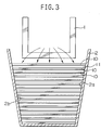
- a water-granulation apparatus for slag in accordance with a first embodiment of the present invention differs from the conventional apparatus only in the structure as depicted in Fig. 3, and hence Fig. 1 is hereinafter used in order to specify the remaining construction of the apparatus.
- the receiving launder (receiving device) 2 includes upstream and downstream ends, and is inclined downwardly from the upstream end to the downstream end. As specifically seen from Fig. 3, the receiving launder 2 has opposite side plates 2a and 2b defining widthwise space therebetween and sloping outwardly in an upward direction such that it has an inner width greater than the discharging launder 1.
- the water-jetting device 3 includes a plurality of partitioning plates 10 instead of the water nozzles 3a.
- the partitioning plates 10 are arranged in the receiving launder 2 at its upstream end so as to span the widthwise space between the opposing side plates 2a and 2b thereof, with the opposite ends of a respective partitioning plate being welded to the inner surfaces of the side plates of the receiving launder 2, and are spaced from each other so as to define a plurality of water outlets 11 of a constant width between respective adjacent partitioning plates 10. Furthermore, as is the case with the conventional apparatus, a tubular member 3b, to which a water conduit 3a is connected, is connected to the upstream side of the partitioning plates 10. In the foregoing, it is preferable that the partitioning plates 10 as well as the receiving launder 2 be formed of stainless steel.
- granulating water is supplied into the water outlets 11 via the conduit 3c and the tubular member 3b.
- the granulating water thus supplied is jetted out from the water outlets 11, defined between the respective adjacent partitioning plates 10, in a direction in which the receiving launder 2 extends, and contacts the high temperature slag, being discharged from the discharging end 1a of the discharging launder 1 towards the receiving launder 2.
- the slag is rapidly quenched and water-granulated.
- the partitioning plates 10 defining elongated water outlets 11 are utilized instead of water nozzles of a tubular shape, the granulating water, jetted out from the water outlets 11, immediately comes into contact with the side walls 2a and 2b of the receiving launder 2.
- the granulating water is positively jetted even against the zone proximate to the upper end of the receiving launder 2, i.e., the region where the slag remains ungranulated in the conventional apparatus, to avoid direct contact of the slag to the receiving launder 2, and the slag can be completely granulated without adhering to the receiving launder 2. Accordingly, phreatic explosions can be prevented from occurring.
- Figs. 4 to 6 depict a modified granulation apparatus in accordance with another embodiment of the invention. More specifically, during smelting and/or converting operations, slag may adhere to the discharging end of the discharging launder 1, being cooled and grown into solidified lumps after a prescribed duration. These solidified lumps of slag, i.e., accretion, should be removed by the operator. In addition, it is naturally required for the operator to inspect the inside of the water-granulation apparatus. Accordingly, the granulation apparatus is modified to facilitate the above removing and inspection operations.
- the modified apparatus includes an explosion-proof hood 12 having a hood body 13 surrounding the discharging end of the discharging launder 1 and the receiving launder 2, and a tubular portion 14 of a rectangular cross-section extending upwards from the forward portion of the hood body 13, below which the discharging launder 1 is not located.
- the exhaust gas produced during water-granulation is discharged through the tubular portion 14.
- the hood body 13 is defined by a front vertical wall 13a, a rear vertical wall 13b, an upper horizontal wall 13c or roof, and a pair of side vertical walls 13d and 13e lying between the front and rear walls 13a and 13b.
- the discharging launder 1 is inserted through the rear wall 13b thereof and terminates in the hood body 13, whereas the receiving launder 2 is inserted through the rear and front walls 13b and 13a thereof.
- the tubular portion 14 is defined by a front wall 14a flush with that of the hood body 13, a rear wall 14b extending upwards from the upper horizontal wall 13c thereof, and side walls 14c and 14d lying between the front and rear walls 14a and 14b and being flush with the side walls of the hood body 13.
- a cooling water conduit 15 having a great number of nozzles 16 provided thereon is disposed along the inner surfaces of the side walls 13d and 13e and the front wall 13a of the hood body 13, and a unit (not shown) for supplying cooling water is connected to the conduit 15.
- a unit (not shown) for supplying cooling water is connected to the conduit 15.
- high pressure cooling water is supplied into the conduit 15, and is jetted, like a shower, through the nozzles 16 against the inner surfaces of the hood walls.
- the cooling water jetted against and falling along the hood walls is gathered by the catchment member 17 into the receiving launder 2.
- an inspection hole 18 is formed through the upper horizontal wall 13c of the explosion-proof hood 12, which wall is located above the discharging launder 1, and a cover lid 19 for covering the inspection hole 18 is releasably attached thereto.
- an aperture 20 of a predetermined cross-section which is used for the operation of a removing unit 21 of accretion adhering to the discharging launder 1, is formed through the portion of the side wall 13e of the hood body 13 proximate to the terminating end of the discharging launder 1, and a cover 22 for closing the aperture 20 is attached thereto for sliding movement.
- first access foothold or scaffold 23 and a second access foothold 24 are mounted adjacent to the side walls 13d and 13e of the hood 12, respectively.
- the first access foothold 23 is formed so as to have a height close to that of the inspection hole 18, in order to permit the operator to inspect the inside of the granulation apparatus easily through the inspection hole 18.
- the removing unit 21 is mounted on the second access foothold 24, and includes a base 25 mounted thereon, a pneumatic cylinder device 26 supported on the base 25 with its cylinder rod being extensibly directed to the aperture 22 of the hood 12, and a chipper 27 mounted on the forward end of the cylinder rod of the cylinder device 26.
- the cover 22 is slided into a closed position in which the aperture 20 is closed.
- the cover 22 is slided into an open position in which the aperture 20 is opened.
- the pneumatic cylinder device 26 is activated to extend its rod to bring the chipper 27 through the aperture 22 into the hood 12 to hit the accretion adhering to the end of the discharging launder 1.
- the slag, being discharged from the discharging launder 1 is granulated by the high pressure granulating water jetted from the water-jetting device 3, and is received by the receiving launder 2.
- the explosion-proof hood 12 which covers the discharging end of the discharging launder 1, molten slag is prevented from being scattered outside.
- molten slag may contact the inner surfaces of the hood walls.
- cooling water is supplied from the conduit 15 and is falling along the inner surfaces of the hood walls, the slag thus contacting thereat is cooled and solidified, and is gathered by the stainless steel catchment member 17 into the receiving launder 2. Therefore, the slag is certainly prevented from adhering to the hood walls.
- the inside of the granulation apparatus as well as the removal operation of the accretion can be inspected easily and safely.
- the terminal end of the discharging launder 1 defines a discharging outlet
- the discharging launder may be constructed so as to have an outlet at a position shifted from the terminal end.
- the cover lid 19 closing the inspection hole 18 may be formed of a heat resistant glass material so as to enable safe inspection even during the operation of the granulation. If the cooling water is also jetted upwards against the inside of the glass cover, the cover is maintained clean, so that visibility will not be lost.
- a burner may be provided so as to extend through the inspection hole into the hood in order to heat the terminal end of the discharging launder 1.
Landscapes
- Engineering & Computer Science (AREA)
- Chemical & Material Sciences (AREA)
- Manufacturing & Machinery (AREA)
- Materials Engineering (AREA)
- Metallurgy (AREA)
- Organic Chemistry (AREA)
- General Life Sciences & Earth Sciences (AREA)
- Environmental & Geological Engineering (AREA)
- Life Sciences & Earth Sciences (AREA)
- Geology (AREA)
- Mechanical Engineering (AREA)
- Geochemistry & Mineralogy (AREA)
- Furnace Details (AREA)
- Disintegrating Or Milling (AREA)
- Glanulating (AREA)
- Gasification And Melting Of Waste (AREA)
Applications Claiming Priority (4)
| Application Number | Priority Date | Filing Date | Title |
|---|---|---|---|
| JP187147/93 | 1993-06-30 | ||
| JP18714793A JP3246098B2 (ja) | 1993-06-30 | 1993-06-30 | 製錬炉におけるカラミの水砕装置 |
| JP5223734A JPH0783577A (ja) | 1993-09-08 | 1993-09-08 | カラミ水砕装置の防爆フード |
| JP223734/93 | 1993-09-08 |
Publications (1)
| Publication Number | Publication Date |
|---|---|
| EP0636697A1 true EP0636697A1 (fr) | 1995-02-01 |
Family
ID=26504178
Family Applications (1)
| Application Number | Title | Priority Date | Filing Date |
|---|---|---|---|
| EP19940109982 Withdrawn EP0636697A1 (fr) | 1993-06-30 | 1994-06-28 | Appareil pour la granulation à l'eau du laitier |
Country Status (7)
| Country | Link |
|---|---|
| US (1) | US5441205A (fr) |
| EP (1) | EP0636697A1 (fr) |
| KR (1) | KR100205773B1 (fr) |
| CN (1) | CN1103484A (fr) |
| AU (1) | AU672698B2 (fr) |
| CA (1) | CA2127017A1 (fr) |
| FI (1) | FI943102A7 (fr) |
Cited By (1)
| Publication number | Priority date | Publication date | Assignee | Title |
|---|---|---|---|---|
| WO1997020624A1 (fr) * | 1995-12-07 | 1997-06-12 | Elkem Asa | Dispositif de granulation de metaux et de laitier en fusion |
Families Citing this family (12)
| Publication number | Priority date | Publication date | Assignee | Title |
|---|---|---|---|---|
| AT400140B (de) * | 1993-12-03 | 1995-10-25 | Holderbank Financ Glarus | Verfahren zum granulieren und zerkleinern von schmelzflüssigem material und mahlgut sowie einrichtung zur durchführung dieses verfahrens |
| US6000242A (en) * | 1996-05-31 | 1999-12-14 | Kennecott Holdings Corporation | Apparatus for and process of water granulating matte or slag |
| AT405511B (de) * | 1997-10-29 | 1999-09-27 | Holderbank Financ Glarus | Verfahren zum granulieren und zerkleinern von schmelzflüssigem material sowie vorrichtung zur durchführung dieses verfahrens |
| ES2237647T3 (es) * | 2002-11-25 | 2005-08-01 | Paul Wurth S.A. | Cabezal de pulverizacion para un aparato de granulacion. |
| AT412650B (de) * | 2003-09-25 | 2005-05-25 | Voest Alpine Ind Anlagen | Verfahren und anlage zum granulieren von schlacke |
| US8550384B2 (en) * | 2006-02-17 | 2013-10-08 | Nitta Construction, Inc. | Dust control system and method for a straw blower |
| JP4498410B2 (ja) * | 2007-12-28 | 2010-07-07 | パンパシフィック・カッパー株式会社 | 自溶炉の点検孔用水冷ジャケット構造体 |
| CN102417938A (zh) * | 2011-11-17 | 2012-04-18 | 中冶华天工程技术有限公司 | 用于钢渣热泼的处理装置 |
| CN109321744B (zh) * | 2017-11-13 | 2024-09-13 | 中冶长天国际工程有限责任公司 | 一种混合机强化制粒装置 |
| CN110628971B (zh) * | 2019-11-01 | 2021-11-19 | 鞍钢集团工程技术有限公司 | 一种节能环保型水冲渣方法及装置 |
| CN111578717A (zh) * | 2020-06-02 | 2020-08-25 | 沈阳铝镁设计研究院有限公司 | 一种新型罐式煅烧炉防棚料冷却水套 |
| CN115198041B (zh) * | 2022-07-08 | 2023-10-17 | 中国科学院力学研究所 | 一种用于转盘离心粒化制粉的粒径控制系统、方法及应用 |
Citations (3)
| Publication number | Priority date | Publication date | Assignee | Title |
|---|---|---|---|---|
| FR2284677A1 (fr) * | 1974-05-17 | 1976-04-09 | Babcock Moxey Ltd | Transport et evacuation de laitier de haut fourneau |
| EP0043605A1 (fr) * | 1980-07-04 | 1982-01-13 | Paul Wurth S.A. | Procédé et installation de granulation de laitier |
| EP0082279A1 (fr) * | 1981-11-18 | 1983-06-29 | Paul Wurth S.A. | Procédé et installation de granulation de laitier |
Family Cites Families (5)
| Publication number | Priority date | Publication date | Assignee | Title |
|---|---|---|---|---|
| US3615329A (en) * | 1969-03-18 | 1971-10-26 | American Smelting Refining | A recirculatory system for the granulation of molten slag |
| SU1426956A1 (ru) * | 1984-12-28 | 1988-09-30 | Государственный Союзный Институт По Проектированию Металлургических Заводов "Гипромез" | Установка дл гранул ции металлургического расплава |
| DE3807720A1 (de) * | 1988-03-09 | 1989-09-21 | Norddeutsche Affinerie | Verfahren und vorrichtung zum granulieren fluessiger schlacken |
| JPH04302993A (ja) * | 1991-03-30 | 1992-10-26 | Mitsubishi Materials Corp | 製錬炉におけるカラミの水砕装置 |
| JPH04302994A (ja) * | 1991-03-30 | 1992-10-26 | Mitsubishi Materials Corp | 製錬炉におけるカラミの水砕装置 |
-
1994
- 1994-06-27 AU AU66001/94A patent/AU672698B2/en not_active Ceased
- 1994-06-27 US US08/266,469 patent/US5441205A/en not_active Expired - Fee Related
- 1994-06-28 EP EP19940109982 patent/EP0636697A1/fr not_active Withdrawn
- 1994-06-28 FI FI943102A patent/FI943102A7/fi unknown
- 1994-06-29 CA CA 2127017 patent/CA2127017A1/fr not_active Abandoned
- 1994-06-30 KR KR1019940015602A patent/KR100205773B1/ko not_active Expired - Fee Related
- 1994-06-30 CN CN94107696A patent/CN1103484A/zh active Pending
Patent Citations (3)
| Publication number | Priority date | Publication date | Assignee | Title |
|---|---|---|---|---|
| FR2284677A1 (fr) * | 1974-05-17 | 1976-04-09 | Babcock Moxey Ltd | Transport et evacuation de laitier de haut fourneau |
| EP0043605A1 (fr) * | 1980-07-04 | 1982-01-13 | Paul Wurth S.A. | Procédé et installation de granulation de laitier |
| EP0082279A1 (fr) * | 1981-11-18 | 1983-06-29 | Paul Wurth S.A. | Procédé et installation de granulation de laitier |
Cited By (1)
| Publication number | Priority date | Publication date | Assignee | Title |
|---|---|---|---|---|
| WO1997020624A1 (fr) * | 1995-12-07 | 1997-06-12 | Elkem Asa | Dispositif de granulation de metaux et de laitier en fusion |
Also Published As
| Publication number | Publication date |
|---|---|
| KR950000893A (ko) | 1995-01-03 |
| AU6600194A (en) | 1995-01-12 |
| AU672698B2 (en) | 1996-10-10 |
| FI943102A0 (fi) | 1994-06-28 |
| CN1103484A (zh) | 1995-06-07 |
| CA2127017A1 (fr) | 1994-12-31 |
| KR100205773B1 (ko) | 1999-07-01 |
| FI943102A7 (fi) | 1994-12-31 |
| US5441205A (en) | 1995-08-15 |
Similar Documents
| Publication | Publication Date | Title |
|---|---|---|
| US5441205A (en) | Apparatus for water-granulating slag | |
| EP1512764B1 (fr) | Pompe à métal liquide et four utilisant cette pompe | |
| US4423514A (en) | Continuously fed electric furnace for melting scrap iron | |
| JP2012102998A (ja) | 直接製錬装置 | |
| KR100507883B1 (ko) | 용융 재료의 입상화 장치 및 방법 | |
| US6893607B2 (en) | Elevated discharge gas lift bubble pump and furnace for use therewith | |
| CA2613851C (fr) | Procede et appareil de test des caracteristiques d'une fonte dans un four | |
| CZ284796B6 (cs) | Plnicí zařízení pro přívod tekutého kovu do elektrické pece | |
| JP3534671B2 (ja) | 溶融炉の出滓口開口装置 | |
| CN216073885U (zh) | 出铁口的砌筑固定装置 | |
| JP4159138B2 (ja) | 自溶炉のアップテイク出側水平連結部用水冷ジャケット | |
| JPH0783577A (ja) | カラミ水砕装置の防爆フード | |
| SE517485C2 (sv) | Sätt vid separering av värdefull metall från en smältblanding, samt anordning härför | |
| KR100903639B1 (ko) | 고로의 출선구 분출물 차단장치 | |
| JPS61276685A (ja) | 非鉄冶金炉の立上り煙道出口部におけるアクリシヨンの除去装置 | |
| US5164146A (en) | Foundry furnace having outlet flow passage | |
| JP2522081Y2 (ja) | スラグキャッチャー | |
| KR19980061380U (ko) | 출선구면 이물제거장치 | |
| JP2000210522A (ja) | 連続式溶融炉の排ガスの含有ダスト低減方法及びその装置 | |
| KR20030043266A (ko) | 대탕도에서 와류억제형 내화물 블럭장치 | |
| JPH04302993A (ja) | 製錬炉におけるカラミの水砕装置 | |
| JPH1030884A (ja) | 坩堝炉型アルミニウム溶解装置 | |
| JPH07276039A (ja) | 溶融金属注入ノズルの洗浄ノズル | |
| RU2033430C1 (ru) | Устройство для непрерывной плавки материалов в расплаве | |
| JPS6018430Y2 (ja) | 製錬炉のサイフォン出口部の構造 |
Legal Events
| Date | Code | Title | Description |
|---|---|---|---|
| PUAI | Public reference made under article 153(3) epc to a published international application that has entered the european phase |
Free format text: ORIGINAL CODE: 0009012 |
|
| AK | Designated contracting states |
Kind code of ref document: A1 Designated state(s): BE DE ES GB PT SE |
|
| 17P | Request for examination filed |
Effective date: 19950324 |
|
| STAA | Information on the status of an ep patent application or granted ep patent |
Free format text: STATUS: THE APPLICATION HAS BEEN WITHDRAWN |
|
| 18W | Application withdrawn |
Withdrawal date: 19970314 |