EP0636931A1 - Methode zur Herstellung eines Substrats mit darauf in einer Fenster/Rahmen-Struktur aufgetragenen Filme - Google Patents
Methode zur Herstellung eines Substrats mit darauf in einer Fenster/Rahmen-Struktur aufgetragenen Filme Download PDFInfo
- Publication number
- EP0636931A1 EP0636931A1 EP94111050A EP94111050A EP0636931A1 EP 0636931 A1 EP0636931 A1 EP 0636931A1 EP 94111050 A EP94111050 A EP 94111050A EP 94111050 A EP94111050 A EP 94111050A EP 0636931 A1 EP0636931 A1 EP 0636931A1
- Authority
- EP
- European Patent Office
- Prior art keywords
- light
- film
- substrate
- photoresist film
- window
- Prior art date
- Legal status (The legal status is an assumption and is not a legal conclusion. Google has not performed a legal analysis and makes no representation as to the accuracy of the status listed.)
- Granted
Links
Images


Classifications
-
- G—PHYSICS
- G03—PHOTOGRAPHY; CINEMATOGRAPHY; ANALOGOUS TECHNIQUES USING WAVES OTHER THAN OPTICAL WAVES; ELECTROGRAPHY; HOLOGRAPHY
- G03F—PHOTOMECHANICAL PRODUCTION OF TEXTURED OR PATTERNED SURFACES, e.g. FOR PRINTING, FOR PROCESSING OF SEMICONDUCTOR DEVICES; MATERIALS THEREFOR; ORIGINALS THEREFOR; APPARATUS SPECIALLY ADAPTED THEREFOR
- G03F7/00—Photomechanical, e.g. photolithographic, production of textured or patterned surfaces, e.g. printing surfaces; Materials therefor, e.g. comprising photoresists; Apparatus specially adapted therefor
- G03F7/0005—Production of optical devices or components in so far as characterised by the lithographic processes or materials used therefor
- G03F7/0007—Filters, e.g. additive colour filters; Components for display devices
Definitions
- the present invention relates to a method for manufacturing a substrate having on the surface thereof window-shaped coating films and a frame-shaped, functional coating film having light-screening properties at the regions not occupied with the window-shaped coating films.
- the method of the present invention is particularly useful for producing a color filter used in a color liquid crystal display (LCD), which has window-shaped, colored coating films and a frame-shaped, functional film having a function of screening unnecessary lights or achieving other desirable properties.
- This method is particularly useful for production of a color filter, which is used in a matrix type color display formed using a thin film transistor (TFT) and a color filter.
- TFT thin film transistor
- Liquid crystal displays have so far been used for goods with a small-sized display such as the so-called pocket-sized television.
- the size of liquid crystal displays has rapidly been enlarged in recent years.
- the image quality of liquid crystal displays has also been improved by the development from TN liquid crystals to STN liquid crystals and active driving elements exemplified by TFT, which has enabled the commercialization of goods with a liquid crystal display having as high image quality as cathode-ray tubes.
- TFT active driving elements exemplified by TFT
- Various studies have been conducted for improving the image quality and productivity of the color displays using TFT. Of these studies, the method for forming a light screening film called a black matrix that prevents light leakage toward TFT and improves the image quality (apparent contrast) and the shape of the light screening film are of great concern.
- a method for forming a functional coating film as a black matrix in the gaps of stripe-form colored coating films which comprises foaming stripe-form colored coating films on a plurality of parallel stripe-form conductive circuits arranged on a transparent substrate by an electro-deposition method; coating a negative photoresist composition capable of giving a functional coating film on the whole surface of the substrate so as to cover the stripe-form colored coating films, followed by forming the photoresist film; exposing the photoresist film to light from the opposite side of the photoresist-carrying surface of the substrate so that the stripe-form colored coating films function as a mask; and eliminating the uncured photoresist film (JP-A-62-247331).
- JP-A-62-247331 enables formation of a functional coating film between the stripe-form colored coating films with high precision; however, this method has a problem that a functional coating film is difficult to be formed in the transverse direction of the stripe-form colored coating films to obtain a lattice form.
- the present invention provides a method for manufacturing a substrate having electrically conductive circuits on the surface thereof, window-shaped coating films on the circuits and a frame-shaped, functional coating film at the regions not occupied with the window-shaped coating films, which comprises the steps of:
- Fig. 1 is a cross-sectional schematic view illustrating the products formed through respective steps of the method of the present invention.
- (I) is a transparent substrate having a plurality of electrically conductive circuits;
- (II) is an intermediate product obtained through step (a);
- (III) is an intermediate product obtained through steps (b), (c) and (d);
- (IV) is an intermediate product obtained through step (e);
- (V) is an intermediate product obtained through step (f); and
- (VI) is a final product obtained through steps (g), (h) and (i).
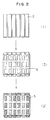
- Fig. 2 is a schematic plan view exemplifying respective patterns of the conductive circuits, the frame-shaped coating film and the window-shaped coating films.
- FIG. 2 (I) exemplifies a pattern of the conductive circuits, (III) a pattern of the frame-shaped photoresist film obtained after elimination of those in the window-shaped parts in step (c), and (IV) a pattern of the window-shaped coating film obtained through step (e).
- Fig. 3 is another schematic plan view exemplifying respective patterns of the conductive circuits and intermediate products.
- FIG. 3 (I) exemplifies a pattern of the conductive circuits, (III) a pattern of the photoresist film after elimination of those in both the window-shaped parts and the parts adjacent to the left and right sides of the window-shaped parts in step (c), and (IV) a pattern of the coating film obtained through step (e).
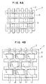
- Fig. 4 is a schematic plan view exemplifying respective patterns of the conductive circuits and the photomask usable in the present invention.
- Fig. 4A the conductive circuits are patterned in a parallel stripe-form, and the photomask are patterned so as to eliminate both the photoresist films in the window-shaped parts on the conductive circuits and those in the parts adjacent to the left and right sides of the window-shaped parts
- Fig. 4B the conductive circuits in a modified parallel stripe-form, and the photomask so as to eliminate the photo-resist film in the window-shaped parts.
- 1 is a transparent substrate
- 2 is an electrically conductive circuit
- 3 is a photoresist coating film
- 4 is a window-shaped vacant hole
- 5 is a window-shaped coating film
- 6 is a frame-shaped coating film
- 7 is a photomask
- 8 is a transparent part of the photomask
- 9 is a light-screening part of the photomask
- 11 is a coating film (red) formed in the window-shaped vacant hole
- 12 is a coating film (green) formed in the window-shaped vacant hole
- 13 is a coating film (blue) formed in the window-shaped vacant hole.
- the transparent substrate which can be used in the present invention includes glass boards, plastic boards and the like.
- the electrically conductive circuits formed on the substrate are prepared from a transparent conductive material such as ITO film (tin-doped indium oxide film), NESA film (antimony-doped tin oxide film) and the like.
- the pattern of the electrically conductive circuits is usually a parallel arrangement of stripes.
- stripe involves not only a longitudinally extended straight line as shown in Fig. 4A but also a line picturing a convexity or concavity from the left side to the right side as shown in Fig. 4B. These stripes can be produced in a conventional manner.
- Step (a) of the present invention is a step of coating the transparent substrate having electrically conductive circuits on the surface thereof with a negative or positive photoresist composition to cover the whole circuits-carrying surface of the substrate, followed by forming a negative or positive photoresist film.
- Examples of the positive photoresist composition usable in step (a) include a composition containing a novolac type phenolic resin and an esterified product of o-quinonediazide, and the like.
- Commercially available positive photoresist compositions are OFPR-800 (trade name, manufactured by Tokyo Ohka Co., Ltd.), PF-7400 (trade name, manufactured by Sumitomo Chemical Co., Ltd.), FH-2030 (trade name, manufactured by Fuji Hant Electronics Technology Co., Ltd.), etc.
- the negative photoresist composition usable in step (a) includes a composition containing an acrylate resin and a photo-polymerization initiator such as benzophenone compounds, anthraquinone compounds and the like, etc.
- a photo-polymerization initiator such as benzophenone compounds, anthraquinone compounds and the like, etc.
- Commercially available negative photoresist compositions are OMR-83 (trade name, manufactured by Tokyo Ohka Co., Ltd.).
- the spin coating method is recommendable because of high fidelity and high precision.
- a solvent e.g. non-reactive solvent such as ethyl cellosolve acetate etc.
- the total amount of the solvent is particularly preferable to adjust the total amount of the solvent to 5 to 40 parts by weight per 100 parts by weight of the photoresist composition.
- the whirler in two stages in a manner such that the photoresist composition is spread on a substrate at 100-400 rpm in the first stage, and thickness of the photoresist composition is made even at 800-5,000 rpm in the second stage.
- the negative or positive photoresist composition coated on the substrate having conductive circuits is preferably heat-treated at 60°-100°C for 5-60 minutes, thereby forming the photoresist film.
- the resin in the negative or positive photoresist composition is preliminarily cured, and the adhesion of the photoresist film to the substrate having conductive circuits is improved.
- Step (b) of the present invention is a step of superposing, on the surface of the photoresist film formed through step (a), a photomask having a pattern designed so as to give the photoresist film in a desired shape prescribed in the following step (c), and exposing the thus masked photoresist film to light.
- FIGs. 4A and 4B Schematic plan views of some examples of the photomask and the ground electrically conductive circuits are shown in Figs. 4A and 4B.
- the photomask patterns shown in Figs. 4A and 4B are examples which can give a coating film not covering the window-shaped parts and the parts adjacent to left and right sides thereof but covering the other parts in the following step (c).
- the photomask used in step (b) has any of the following patterns:
- the film is a positive photoresist film
- the photoresist film under the light-screening part of the mask is cured by exposure and remains after development as a part insoluble in developing solution, while the photoresist film located under the transparent parts of the mask is decomposed and eliminated after development.
- the film is a negative photoresist film, a reverse phenomenon takes place.
- step (b) lights of various wavelength ranges can be used depending on the kind of the positive or negative photoresist film. Generally speaking, lights of UV region are desirable.
- the light source apparatuses using super-high pressure mercury lamp, metal halide lamp and the like can be used. From the viewpoint of accuracy of patterning, those apparatuses which have a mirror type of parallel light structure are preferred.
- the conditions of exposure vary depending on the light source and the kind of photoresist film.
- the light exposure is usually in the range of 10-500 mJ/cm2.
- a decomposition reaction progresses, whereby the resist becomes soluble in the developing solutions mentioned later.
- the light exposure is usually in the range of 10-500 mJ/cm2.
- no curing reaction progresses, so that such regions remain soluble in the developing solutions mentioned later.
- Step (c) of the present invention is a step of subjecting the resulting substrate formed through steps (a) and (b) to development, eliminating the photoresist film in the window-shaped parts on the electrically conductive circuits or both the photoresist film in the window-shaped parts on the electrically conductive circuits and that in the parts adjacent to one or both of the left and right sides of the window-shaped parts and leaving the photoresist film in the other parts.
- the agent used for the development is appropriately selected depending on the kind of the negative or positive photoresist film.
- examples thereof are aqueous alkaline solutions of caustic soda, sodium carbonate, quaternary ammonium salts, organic amines or the like, and organic solvents such as esters, ketones, alcohols, aromatic hydrocarbons, chlorinated hydrocarbons and the like.
- the elimination can be effected by dipping or showering the substrate in or with the developing agent for a period ranging from 5 seconds to about 3 minutes. Subsequently, the resulting substrate is thoroughly rinsed with city water, deionized water or the like.
- Step (d) of the present invention is a step of subjecting the photoresist film left in step (c) to heat-treatment, second exposure to light or no treatment.
- the heat treatment can be carried out for the purpose of suppressing the reaction between the positive or negative photoresist film formed in step (c) and the electro-deposition coating films formed in the following step (e), which reaction would take place in the course of optional heat-treatment of the electro-deposition coating films in step (e), and for the purpose of facilitating the elimination of the positive or negative photoresist film in step (f).
- the heat treatment can be prevented defects such that the positive or negative photoresist film remains in the neighborhood of electro-deposition coating films even after the elimination procedure in step (f), the electro-deposition coating films are easy to peel, and the desired functional coating film is damaged.
- the heat treatment is preferably carried out at 150°-240°C for 0.5-2 hours, and more preferably at 200°-220°C for about one hour.
- Second exposure to light can be carried out for the purpose of facilitating the elimination of the photoresist film after forming an electro-deposition coating film on the window-shaped parts in the subsequent step, particularly when the photoresist composition used in step (a) is positive.
- the positive photoresist film is photo-degraded and becomes readily soluble in the developing agent such as aqueous alkaline solutions and the like.
- the light exposure in this second exposure treatment preferably falls within the range of 100-400 mJ/cm2, although it may vary depending upon the kind of positive photoresist.
- step (d) is heat-treatment or second exposure to light.
- the treatment of this step (d) is preferably heat treatment.
- the treatment of this step (d) is preferably heat treatment or no treatment.
- step (d) When the photoresist composition used in step (a) is a positive photoresist composition, the treatment of this step (d) is preferably second exposure to light.
- Step (e) of the present invention is a step of subjecting the substrate formed through steps (a) to (d) in this order to electro-deposition using the circuits on the substrate as one electrode, forming electro-deposition coating films at the window-shaped parts on the circuits, the electro-deposition coating films being capable of screening light emitted in the following step (h).
- a resin material (binder) used in the electro-deposition includes, for example, maleinated oil type, acrylic type, polyester type, polybutadiene type and polyolefin type resin materials. These resin materials may be used either singly or in the form of mixture.
- an electro-depositing solution is usually prepared by dispersing a binder and other ingredients in water and diluting the resulting dispersion.
- the electro-depositing solution not only aqueous electro-depositing solutions but also non-aqueous electro-depositing solutions using an organic solvents are usable.
- a transparent substrate formed through the above-mentioned steps (a) to (d) in this order is introduced into a bath containing the electro-depositing solution.
- the conductive circuits on the substrate are used as positive electrode, and a corrosion-resistant, electrically conductive material (e.g. stainless steel or the like) is used as a counter electrode, and then a direct current voltage is applied.
- electro-deposition coating films are selectively formed in the window-shaped parts on the conductive circuits. No electro-deposition coating film is formed in the parts where the photoresist film exists and in the parts where the conductive circuits do not exist.
- the thickness of the electro-deposition coating films can be controlled by changing the conditions of electro-deposition. Usually, the period of the electro-deposition is from about 1 second to about 3 minutes at a voltage of 10-300 V. After formation of electro-deposition coating films, the coating films are thoroughly washed to remove unnecessary substances therefrom. If desired, the coating films are heat-treated at 90°-280°C for 10-120 minutes in order to enhance its strength.
- the lower limit of the temperature is preferably 100°C
- the upper limit of the temperature is preferably 150°C
- the longer limit of the period is preferably 60 minutes.
- Step (f) of the present invention is a step of eliminating the photoresist film having been subjected to heat-treatment, second exposure to light or no treatment in step (d) and leaving the electro-deposition coating films formed in step (e).
- a method for eliminating the photoresist film is known in the field of printed circuit forming technique [for example, Circuit Technology, Vol. 4, No. 4 (1989), p. 197; "Printed Circuit Boards", Sentangijutsu Shuusei, published by Keiei System Kenkyusho (Feb. 10, 1987), p. 308].
- the elimination of the photoresist film can be carried out by contacting the photoresist film with an appropriate dissolving agent.
- the dissolving agent is selected in accordance with the kinds of the photoresist film to be eliminated and electro-deposition coating film.
- Examples thereof are an aqueous alkaline solution of caustic soda, sodium carbonate, quaternary ammonium salts, organic amines or the like and an organic solvent such as esters, ketones, alcohols, ethers, chlorinated hydrocarbons and the like.
- the elimination of the photoresist film can be effected by the method of dipping or showering for a period of 30 seconds to about 20 minutes. A rubbing means such as brush, woven fabric and the like may be used. Thereafter, the thus treated substrate may be rinsed thoroughly with organic solvent, water or the like.
- the electro-deposition coating film is baked by a heat treatment at 100°-280°C for 5-120 minutes.
- the shorter limit of the time period is preferably 10 minutes, and the longer limit of the time period is preferably 60 minutes.
- Step (g) of the present invention is a step of coating the substrate formed through the steps (a) to (f) in this order with a negative photoresist composition capable of giving a functional coating film to cover the whole conductive circuits-carrying surface of the substrate, followed by forming a functional coating film.
- the coating film formed in this step has a function such as a black matrix of color filter for use in LCD.
- the coating can be carried out by a method capable of giving a uniform coating film, such as spin coating method, roll coating method, screen printing method, offset printing method, dip coating method and the like.
- Preferred negative photoresist compositions include the so-called UV-curable photoresist composition.
- the main ingredient thereof includes, for example, acryl, urethane or epoxy resin, synthetic rubber, polyvinyl alcohols, gums or gelatin. These ingredients may be used either singly or in the form of mixture.
- the compositions thus prepared are commercially available as photo-curable paints, inks and negative resists. Into these compositions, a reactive diluent, a reaction initiator, a photo sensitizer and the like may optionally be incorporated.
- additives may be added thereto.
- an appropriate pigment or light-screening agent may be added.
- an appropriate adhesion-improving material may be added.
- the composition may be diluted to an appropriate viscosity or an appropriate solid content in order to improve the workability, by the use of an appropriate organic solvent in the case of organic solvent-dilution type compositions or by the use of water in the case of water-dilution type compositions.
- the substrate coated with the negative photoresist composition is preferably heat-treated at 60°-120°C for 1-30 minutes to form the functional coating film.
- Step (h) of the present invention is a step of exposing the substrate formed through steps (a) to (g) in this order to light emitted from the opposite side of the conductive circuit-carrying surface of the substrate.
- lights of various wavelength ranges may be used depending on the kind of the negative photoresist. Generally speaking, lights of the UV region are preferred.
- the light source apparatuses using super-high pressure mercury lamp, metal halide lamp or the like can be used.
- the conditions of exposure vary depending on the light source and the kind of negative photoresist, the light exposure is usually within the range of 100-2,000 mJ/cm2 and the time period of exposure is usually within the range of 0.1-60 seconds. In the area exposed to light, a crosslinking reaction progresses whereby the functional coating film becomes insoluble and cures.
- Step (i) of the present invention is a step of eliminating from the functional coating film the uncured parts which have not been exposed to light in step (h).
- the elimination is carried out by contacting the functional coating film with an appropriate dissolving agent, such as a developing solution, and thereby dissolving out the uncured parts of the functional coating film.
- an appropriate dissolving agent such as a developing solution
- the agent is appropriately selected in accordance with the kind of negative photoresist film. Examples thereof are aqueous alkaline solutions of caustic soda, sodium carbonate, quaternary ammonium salts, organic amines or the like and organic solvents such as esters, ketones, alcohols, chlorinated hydrocarbons and the like.
- the dissolution of the uncured photoresist film may be carried out by the method of dipping or showering the substrate in or with the agent for a time period of 30 seconds to about 5 minutes.
- the thus treated substrate is thoroughly washed with water, organic solvents or the like.
- the washed substrate may optionally be heat-treated at 10°-280°C and preferably at 100°-280°C, for a period of 10-120 minutes and preferably for 10-12 minutes.
- the window-shaped, colored electro-deposition coating film and a frame-shaped, functional film having a function of black matrix are formed on a transparent substrate having electrically conductive circuits on its surface by the method of the present invention, and subsequently an overcoat film (protecting film) is formed thereon as occasion demands.
- the material for the overcoat film includes, for example, epoxy type, polyimide type and acrylate type resins.
- the overcoat film is formed by applying such a resin by means of spin coater, roll coater or the like, and thereafter thermally baking the resin.
- Stripe-form ITO circuits (sheet resistance: 15 ⁇ / ⁇ ) each having a width of 80 ⁇ m were formed in parallel and linearly on a glass substrate having a thickness of 1.1 mm, at intervals of 20 ⁇ m (100 ⁇ m pitch).
- a positive photoresist film having a film thickness of 1.5 ⁇ m was formed by adding 20 parts by weight of ethyl cellosolve acetate to 100 parts by weight of a positive photoresist composition (trade name: FH2030, manufactured by Fuji Hant Electronics Technology Co.) to obtain a mixture, coating the whole surface of the transparent substrate obtained in (1) with the mixture obtained above by spin coating method in two stages, namely firstly at 200 rpm/5 seconds and secondly at 1,000 rpm/20 seconds, and heat-treating the resulting coat at 90°C for 30 minutes.
- This procedure illustrates step (a) of the present invention.
- a lattice-wise patterned photomask having light-screening window-shaped parts of one window size of 60 ⁇ m x 200 ⁇ m was aligned with the ground transparent conductive circuit pattern (lines/spaces: 80 ⁇ m/20 ⁇ m) so as to locate the window-parts on the circuit line.
- the gap between the photomask and the photoresist film was 30 ⁇ m.
- the resulting product was exposed to light at a light exposure of 100 mJ/cm2 with Proximity Exposing Machine (MAP-1200, manufactured by Dainippon Kaken Co.) using super-high pressure mercury lamp as light source.
- MAP-1200 Proximity Exposing Machine
- the substrate obtained in (4) having a lattice-form, frame-shaped positive photoresist film was heat-treated in an oven at 220°C for one hour. This procedure illustrates step (d) of the present invention.
- electro-deposition was carried out in order of red, green and blue coatings.
- the electro-deposition was carried out at 50-80 V for a period of 10-20 seconds, which conditions were varied depending on the color. Then, the resulting electro-deposited films were thoroughly washed with water and heat-treated at 260°C for one hour.
- red-, green- and blue-colored films each having a thickness of 1.2 ⁇ m were formed in the prescribed order in the window-shaped pits carrying no positive photoresist film. These films had properties of screening UV light used in (9) described below. This procedure illustrates step (e) of the present invention.
- the transparent substrate obtained by the above-mentioned steps was immersed in 5% by weight caustic soda solution heated to 40°C for 15 minutes, and then the positive photoresist film on the substrate was brushed while showering deionized water to eliminate and peel off the positive photoresist film only. Then, the resulting product was thoroughly washed, air-dried and heat-treated at 200°C for 30 minutes. This procedure illustrates step (f) of the present invention.
- a coating material for black mask (negative photoresist, manufactured by Shinto-Chemitron Co.) was coated by the screen printing method on the whole surface of the substrate obtained in (7). After the coating, the coating film was heat-treated at 100°C for 10 minutes. The film thus formed had a thickness of about 8 ⁇ m. This procedure illustrates step (g) of the present invention.
- the substrate obtained in (8) was exposed to UV light from the opposite side of the conductive circuits-carrying surface at a distance of 10 cm for a period of 10 seconds.
- the light exposure was 1,800 mJ/cm2.
- the main wavelengths of the UV light used herein were 313 nm and 365 nm.
- the procedure illustrates step (h) of the present invention.
- the substrate obtained in (9) was then immersed in ethyl cellosolve acetate for 2 minutes, while applying ultrasonic wave thereto, whereby the coating film of the unexposed parts [the parts obstructed from exposure due to the existence of light-screening film formed in (6)] was eliminated. Then, the resulting product was immersed in an ethyl cellosolve acetate washing liquor for 30 seconds, and thereafter immersed in isopropyl alcohol and deionized water successively each for a period of 30 seconds. Then, the resulting product was heated and the remaining films were cured at 230°C for 30 minutes.
- Fig. 2 shows the pattern of the thus obtained window-shaped, color films and the lattice-form, frame-shaped functional film.
- stripe-form ITO circuits (sheet resistance: 15 ⁇ / ⁇ ) each having a width of 80 ⁇ m were formed in parallel and linearly at intervals of 20 ⁇ m (100 ⁇ m pitch).
- a positive photoresist film having a film thickness of 1.5 ⁇ m was formed by adding 20 parts by weight of ethyl cellosolve acetate to 100 parts by weight of a positive photoresist composition (trade name: FH2030, manufactured by Fuji Hant Electronics Technology Co.) to obtain a mixture, coating the whole surface of the transparent substrate obtained in (1) with the mixture obtained above by spin coating method in two stages, namely first at 200 rpm/5 seconds and secondly at 1,000 rpm/20 seconds, and heat-treating the resulting coat at 90°C for 30 minutes.
- This procedure illustrates step (a) of the present invention.
- a photomask with a pattern of alternately pictured light-screening lines and transparent spaces (lines/spaces: 100 ⁇ m/200 ⁇ m) was aligned with the ground parallel, stripe-form, transparent, electrically conductive circuits (lines/spaces: 80 ⁇ m/20 ⁇ m) so that the lines and spaces of the photomask were placed perpendicularly to the longitudinal direction of the conductive circuits.
- the gap between the photomask and the photoresist film was 30 ⁇ m.
- step (b) of the present invention illustrates step (b) of the present invention.
- step (c) of the present invention illustrates step (c) of the present invention.
- the substrate obtained in (4) having linear positive photoresist films was heat-treated in an oven at 220°C for one hour. This procedure illustrates step (d) of the present invention.
- electro-deposition was carried out in order of red, green and blue coatings.
- the electro-deposition was carried out at 50-80 V for a period of 10-20 seconds, which conditions were varied depending on the color. Then, the resulting electro-deposited films were thoroughly washed with water and heat-treated at 260°C for one hour.
- red-, green- and blue-colored films each having a thickness of 1.2 ⁇ m were formed in the prescribed order in the window-shaped pits carrying no positive photoresist film. These films had properties of screening UV light used in (9) described below. This procedure illustrates step (e) of the present invention.
- the transparent substrate obtained by the above-mentioned steps was immersed in 5% by weight caustic soda solution heated to 40°C for 15 minutes, and then the positive photoresist films on the substrate was brushed while showering deionized water to eliminate and peel off the positive photoresist films only. Then, the resulting product was thoroughly washed, air-dried and heat-treated at 200°C for 30 minutes. This procedure illustrates step (f) of the present invention.
- a coating material for black mask (negative photoresist, manufactured by Shinto-Chemitron Co.) was coated by the screen printing method on the whole surface of the substrate obtained in (7). After the coating, the coating film was heat-treated at 100°C for 10 minutes. The film thus formed had a thickness of about 8 ⁇ m. This procedure illustrates step (g) of the present invention.
- the substrate obtained in (8) was exposed to UV light of 80 W from the opposite side of the conductive circuits-carrying surface at a distance of 10 cm for a period of 10 seconds.
- the light exposure was 1,800 mJ/cm2.
- the main wavelengths of the UV light used herein were 313 nm and 365 nm. This procedure illustrates step (h) of the present invention.
- the substrate obtained in (9) was then immersed in ethyl cellosolve acetate for 2 minutes, while applying ultrasonic wave thereto, whereby the coating film of the unexposed parts [the parts obstructed from exposure due to the existence of light-screening film formed in (6)] was eliminated. Then, the resulting product was immersed in an ethyl cellosolve acetate washing liquor for 30 seconds, and thereafter immersed in isopropyl alcohol and deionized water successively each for a period of 30 seconds. Then, the resulting product was heated and the remaining films were cured at 230°C for 30 minutes.
- Fig. 3 shows the pattern of the thus obtained window-shaped, color films and the lattice-form, frame-shaped functional film.
- Stripe-form ITO circuits (sheet resistance: 15 ⁇ / ⁇ ) each having a width of 80 ⁇ m were formed in parallel and linearly on a glass substrate having a thickness of 1.1 mm, at intervals of 20 ⁇ m (100 ⁇ m pitch).
- a positive photoresist film having a film thickness of 1.5 ⁇ m was formed by adding 20 parts by weight of ethyl cellosolve acetate to 100 parts by weight of a positive photoresist composition (tradename: FH2030, manufactured by Fuji Hant Electronics Technology Co.) to obtain a mixture, coating the whole surface of the transparent substrate obtained in (1) with the mixture obtained above by spin coating method in two stages, namely firstly at 200 rpm/5 seconds and secondly at 1,000 rpm/20 seconds, and heat-treating the resulting coat at 90°C for 30 minutes.
- This procedure illustrates step (a) of the present invention.
- a photomask with a pattern of alternately pictured light-screening lines and transparent spaces (lines/spaces: 100 ⁇ m/200 ⁇ m) was aligned with the ground parallel, stripe-form, transparent, electrically conductive circuits (lines/spaces: 80 ⁇ m/20 ⁇ m) so that the lines and spaces of the photomask were placed perpendicularly to the longitudinal direction of the conductive circuits.
- the gap between the photomask and the photoresist film was 30 ⁇ m.
- step (b) of the present invention illustrates step (b) of the present invention.
- step (c) of the present invention illustrates step (c) of the present invention.
- electro-deposition was carried out in order of red, green and blue coatings.
- the electro-deposition was carried out at 50-80 V for a period of 10-20 seconds, which conditions were varied depending on the color. Then, the resulting electro-deposited films were thoroughly washed with water and heat-treated at 120°C for one hour.
- red-, green- and blue-colored films each having a thickness of 1.2 ⁇ m were formed in the prescribed order in the window-shaped pits carrying no positive photoresist film. These films had properties of screening UV light used in (8) described below. This procedure illustrates step (e) of the present invention.
- the transparent substrate obtained by the above-mentioned steps was immersed in a stripping solution (tradename: Stripper #10, manufactured by Tokyo Ohka Kogyo Co.) for 5 minutes to eliminate and peel off the positive photoresist films only. Thereafter, the resulting product was thoroughly washed, air-dried and heat-treated at 270°C for 60 minutes.
- Stripper #10 manufactured by Tokyo Ohka Kogyo Co.
- a coating material for black mask (negative photoresist, manufactured by Shinto-Chemitron Co.) was coated by the screen printing method on the whole surface of the substrate obtained in (6). After the coating, the coating film was heat-treated at 100°C for 10 minutes. The film thus formed had a thickness of about 8 ⁇ m.
- This procedure illustrates step (g) of the present invention.
- the substrate obtained in (7) was exposed to UV light of 80 W from the opposite side of the conductive circuits-carrying surface at a distance of 10 cm for a period of 10 seconds.
- the light exposure was 1,800 mJ/cm2.
- the main wavelengths of the UV light used herein were 313 nm and 365 nm. This procedure illustrates step (h) of the present invention.
- the substrate obtained in (8) was then immersed in ethyl cellosolve acetate for 2 minutes, while applying ultrasonic wave thereto, whereby the coating film of the unexposed parts [the parts obstructed from exposure due to the existence of light-screening film formed in (5)] was eliminated. Then, the resulting product was immersed in an ethyl cellosolve acetate washing liquor for 30 seconds, and thereafter immersed in isopropyl alcohol and deionized water successively each for a period of 30 seconds. Then, the resulting product was heated and the remaining films were cured at 230°C for 30 minutes.
- Fig. 3 shows the pattern of the thus obtained window-shaped, color films and the lattice-form, frame-shaped functional film.
- Stripe-form ITO circuits (sheet resistance: 15 ⁇ / ⁇ ) each having a width of 80 ⁇ m were formed in parallel and linearly on a glass substrate having a thickness of 1.1 mm, at intervals of 20 ⁇ m (100 ⁇ m pitch).
- a positive photoresist film having a film thickness of 1.5 ⁇ m was formed by adding 20 parts by weight of ethyl cellosolve acetate to 100 parts by weight of a positive photoresist composition (tradename: FH2030, manufactured by Fuji Hant Electronics Technology Co.) to obtain a mixture, coating the whole surface of the transparent substrate obtained in (1) with the mixture obtained above by spin coating method in two stages, namely firstly at 200 rpm/5 seconds and secondly at 1,000 rpm/20 seconds, and heat-treating the resulting coat at 90°C for 30 minutes.
- This procedure illustrates step (a) of the present invention.
- a lattice-wise patterned photomask having light-screening window-shaped parts of one window size of 60 ⁇ m x 200 ⁇ m was aligned with the ground transparent conductive circuits (lines/spaces: 80 ⁇ m/20 ⁇ m) so as to locate the window-parts on the circuit line.
- the gap between the photomask and the photoresist film was 30 ⁇ m.
- the resulting product was exposed to light at a light exposure of 100 mJ/cm2 with Proximity Exposing Machine (MAP-1200, manufactured by Dainippon Kaken Co.) using super-high pressure mercury lamp as light source. This procedure illustrates step (b) of the present invention.
- MAP-1200 Proximity Exposing Machine
- step (c) of the present invention illustrates step (c) of the present invention.
- the substrate obtained in (4) having a lattice-form, frame-shaped positive photoresist film was exposed to light again at a light exposure of 200 mJ/cm2 with Proximity Exposing Machine (MAP-1200, manufactured by Dainippon Kaken Co.) using super-high pressure mercury lamp as light source.
- MAP-1200 Proximity Exposing Machine
- This procedure illustrates step (d) of the present invention.
- electro-deposition was carried out in order of red, green and blue coatings.
- the electro-deposition was carried out at 50-80 V for a period of 10-20 seconds, which conditions were varied depending on the color. Then, the resulting electro-deposited films were thoroughly washed with water and heat-treated at 120°C for 10 minutes.
- red-, green- and blue-colored films each having a thickness of 1.2 ⁇ m were formed in the prescribed order in the window-shaped pits carrying no positive photoresist film. These films had properties of screening UV light used in (9) described below. This procedure illustrates step (e) of the present invention.
- the transparent substrate obtained by the above-mentioned steps was immersed in 5% by weight caustic soda solution at room temperature for 10 minutes, and then the positive photoresist film on the substrate was brushed while showering deionized water to eliminate and peel off the positive photoresist film only. Then, the resulting product was thoroughly washed, air-dried and heat-treated at 260°C for one hour. This procedure illustrates step (f) of the present invention.
- a coating material for black mask (negative photoresist, manufactured by Shinto-Chemitron Co.) was coated by the screen printing method on the whole surface of the substrate obtained in (7). After the coating, the coating film was heat-treated at 100°C for 10 minutes. The film thus formed had a thickness of about 8 ⁇ m. This procedure illustrates step (g) of the present invention.
- the substrate obtained in (8) was exposed to UV light of 80 W from the opposite side of the conductive circuits-carrying surface at a distance of 10 cm for a period of 10 seconds.
- the main wavelengths of the UV light used herein were 313 nm and 365 nm. This procedure illustrates step (h) of the present invention.
- the substrate obtained in (9) was then immersed in ethyl cellosolve acetate for 2 minutes, while applying ultrasonic wave thereto, whereby the coating film of the unexposed parts [the parts obstructed from exposure due to the existence of light-screening film formed in (6)] was eliminated. Then, the resulting product was immersed in an ethyl cellosolve acetate washing liquor for 30 seconds, and thereafter immersed in isopropyl alcohol and deionized water successively each for a period of 30 seconds. Then, the resulting product was heated and the remaining films were cured at 230°C for 30 minutes.
- Fig. 2 shows the pattern of the thus obtained window-shaped, color films and the lattice-form, frame-shaped functional film.
- the method of the present invention there can be formed, on a transparent substrate having a plurality of electrically conductive circuits on a surface thereof, window-shaped, coating films located on the electrically conductive circuits and a frame-shaped, coating film having light-screening properties or other desirable functions at the regions not occupied with the window-shaped coating films with high precision.
- a coating film with fine patterns in which each window-shaped part has a width of less than 100 ⁇ m can be formed with high precision.
- the method of the present invention is suitable for producing, for example, a color filter for use in LCD well prevented from the leakage of light, excellent in clearance of color parts and quite excellent in optical properties, and particularly suitable for producing the color filters used in matrix type color display using TFT and color filters.
Landscapes
- Physics & Mathematics (AREA)
- General Physics & Mathematics (AREA)
- Optical Filters (AREA)
- Exposure And Positioning Against Photoresist Photosensitive Materials (AREA)
- Liquid Crystal (AREA)
- Photosensitive Polymer And Photoresist Processing (AREA)
Applications Claiming Priority (8)
| Application Number | Priority Date | Filing Date | Title |
|---|---|---|---|
| JP18379593A JPH0735919A (ja) | 1993-07-26 | 1993-07-26 | 機能性塗膜等を形成する方法 |
| JP5183794A JPH0735918A (ja) | 1993-07-26 | 1993-07-26 | 基板上に窓部の塗膜と枠部の機能性塗膜を形成する方法 |
| JP183794/93 | 1993-07-26 | ||
| JP183795/93 | 1993-07-26 | ||
| JP18475593A JPH0743516A (ja) | 1993-07-27 | 1993-07-27 | 枠部の機能性塗膜等を形成する方法 |
| JP18475493A JPH0743515A (ja) | 1993-07-27 | 1993-07-27 | 窓部の塗膜と枠部の塗膜を形成する方法 |
| JP184754/93 | 1993-07-27 | ||
| JP184755/93 | 1993-07-27 |
Publications (2)
| Publication Number | Publication Date |
|---|---|
| EP0636931A1 true EP0636931A1 (de) | 1995-02-01 |
| EP0636931B1 EP0636931B1 (de) | 1997-06-04 |
Family
ID=27475127
Family Applications (1)
| Application Number | Title | Priority Date | Filing Date |
|---|---|---|---|
| EP94111050A Expired - Lifetime EP0636931B1 (de) | 1993-07-26 | 1994-07-15 | Methode zur Herstellung eines Substrats mit darauf in einer Fenster/Rahmen-Struktur aufgetragenen Filmen |
Country Status (6)
| Country | Link |
|---|---|
| US (1) | US5578403A (de) |
| EP (1) | EP0636931B1 (de) |
| KR (1) | KR950004439A (de) |
| DE (1) | DE69403576T2 (de) |
| FI (1) | FI943498A7 (de) |
| TW (1) | TW297105B (de) |
Cited By (1)
| Publication number | Priority date | Publication date | Assignee | Title |
|---|---|---|---|---|
| US5681675A (en) * | 1994-05-18 | 1997-10-28 | Kabushiki Kaisha Toshiba | Fabricating method of liquid crystal display apparatus |
Families Citing this family (6)
| Publication number | Priority date | Publication date | Assignee | Title |
|---|---|---|---|---|
| JPH08179302A (ja) * | 1994-12-22 | 1996-07-12 | Seiko Instr Inc | 多色液晶表示装置の製造方法 |
| US5725976A (en) * | 1996-01-30 | 1998-03-10 | Sumitomo Chemical Company, Limited | Method for manufacture of a color filter |
| JP2000017490A (ja) * | 1998-06-29 | 2000-01-18 | Sony Corp | ポリイミド複合電着膜の形成方法 |
| US8017531B2 (en) * | 2001-09-18 | 2011-09-13 | Elkcorp | Composite material |
| US7067236B2 (en) * | 2002-07-19 | 2006-06-27 | Canon Kabushiki Kaisha | Method of manufacturing member pattern, method of manufacturing wiring structure, method of manufacturing electron source, and method of manufacturing image display device |
| US20120121822A1 (en) * | 2010-11-12 | 2012-05-17 | Kai-Ti Yang | Manufacture method for thin film frame layer of display panel |
Citations (2)
| Publication number | Priority date | Publication date | Assignee | Title |
|---|---|---|---|---|
| EP0243121A2 (de) * | 1986-04-21 | 1987-10-28 | Shinto Paint Co., Ltd. | Verfahren zum Herstellen von funktionellen Filmen auf dünnem durchsichtigem elektrisch leitendem Muster, sowie seine Abstände |
| EP0450840A2 (de) * | 1990-04-02 | 1991-10-09 | Seiko Epson Corporation | Verfahren zur Herstellung eines Farbfilters |
Family Cites Families (6)
| Publication number | Priority date | Publication date | Assignee | Title |
|---|---|---|---|---|
| US4311773A (en) * | 1979-02-28 | 1982-01-19 | Hitachi, Ltd. | Method of producing color filters |
| JPS6033506A (ja) * | 1983-08-04 | 1985-02-20 | Seiko Instr & Electronics Ltd | カラ−固体撮像素子の製造方法 |
| JPS62160421A (ja) * | 1986-01-08 | 1987-07-16 | Shinto Paint Co Ltd | 微細な導電性回路の間に機能性塗膜を形成する方法 |
| JP2669826B2 (ja) * | 1987-07-17 | 1997-10-29 | 日本ペイント株式会社 | 着色表示装置の製造方法 |
| US4767723A (en) * | 1987-10-30 | 1988-08-30 | International Business Machines Corporation | Process for making self-aligning thin film transistors |
| JPH0792574B2 (ja) * | 1988-12-21 | 1995-10-09 | インターナショナル・ビジネス・マシーンズ・コーポレーション | 液晶表示装置およびその製造方法 |
-
1994
- 1994-07-12 US US08/273,755 patent/US5578403A/en not_active Expired - Fee Related
- 1994-07-15 DE DE69403576T patent/DE69403576T2/de not_active Expired - Fee Related
- 1994-07-15 EP EP94111050A patent/EP0636931B1/de not_active Expired - Lifetime
- 1994-07-25 TW TW083106787A patent/TW297105B/zh active
- 1994-07-25 FI FI943498A patent/FI943498A7/fi unknown
- 1994-07-26 KR KR1019940018048A patent/KR950004439A/ko not_active Withdrawn
Patent Citations (3)
| Publication number | Priority date | Publication date | Assignee | Title |
|---|---|---|---|---|
| EP0243121A2 (de) * | 1986-04-21 | 1987-10-28 | Shinto Paint Co., Ltd. | Verfahren zum Herstellen von funktionellen Filmen auf dünnem durchsichtigem elektrisch leitendem Muster, sowie seine Abstände |
| JPS62247331A (ja) * | 1986-04-21 | 1987-10-28 | Shinto Paint Co Ltd | 微細な透明導電性回路パタ−ン上およびその間隙に機能性薄膜を形成する方法 |
| EP0450840A2 (de) * | 1990-04-02 | 1991-10-09 | Seiko Epson Corporation | Verfahren zur Herstellung eines Farbfilters |
Cited By (3)
| Publication number | Priority date | Publication date | Assignee | Title |
|---|---|---|---|---|
| US5681675A (en) * | 1994-05-18 | 1997-10-28 | Kabushiki Kaisha Toshiba | Fabricating method of liquid crystal display apparatus |
| US6043857A (en) * | 1994-05-18 | 2000-03-28 | Kabushiki Kaisha Toshiba | Liquid crystal display apparatus |
| US6120943A (en) * | 1994-05-18 | 2000-09-19 | Kabushiki Kaisha Toshiba | Fabricating method of liquid crystal display apparatus |
Also Published As
| Publication number | Publication date |
|---|---|
| DE69403576T2 (de) | 1997-09-18 |
| DE69403576D1 (de) | 1997-07-10 |
| FI943498A0 (fi) | 1994-07-25 |
| EP0636931B1 (de) | 1997-06-04 |
| KR950004439A (ko) | 1995-02-18 |
| US5578403A (en) | 1996-11-26 |
| FI943498A7 (fi) | 1995-01-27 |
| TW297105B (de) | 1997-02-01 |
Similar Documents
| Publication | Publication Date | Title |
|---|---|---|
| US5503952A (en) | Method for manufacture of color filter and liquid crystal display | |
| KR100338428B1 (ko) | 차광층을가진기판의형성방법,차광층을가진기판,흑백표시박막트랜지스터(tft)어레이기판용대향전극기판및흑백표시액정디스플레이장치 | |
| EP0243121B1 (de) | Verfahren zum Herstellen von funktionellen Filmen auf dünnem durchsichtigem elektrisch leitendem Muster, sowie seine Abstände | |
| DE69121161T2 (de) | Farbfilter | |
| US5214541A (en) | Method for producing color filter | |
| US5561011A (en) | Method for manufacturing a substrate having window-shaped coating films and frame-shaped coating film on the surface thereof | |
| US5399449A (en) | Method for producing color filter wherein the voltage used to electrodeposit the colored layers is decreased with each subsequent electrodeposition step | |
| US5578403A (en) | Method for manufacture of a substrate having window-shaped and frame-shaped coating films on the surface thereof | |
| US5503732A (en) | Method for manufacturing a substrate having window-shaped and frame-shaped coating films on the surface thereof | |
| US5641595A (en) | Manufacture of color filters by incremental exposure method | |
| KR100309894B1 (ko) | 기능성도막을형성하는방법 | |
| JPH07301793A (ja) | カラーフィルターおよび液晶表示装置の製造方法 | |
| JPH0743515A (ja) | 窓部の塗膜と枠部の塗膜を形成する方法 | |
| JPH06130379A (ja) | 微細な導電性回路の間に格子状の機能性塗膜を形成する方法 | |
| JPH0735919A (ja) | 機能性塗膜等を形成する方法 | |
| JPH0735918A (ja) | 基板上に窓部の塗膜と枠部の機能性塗膜を形成する方法 | |
| JPH08220339A (ja) | カラ−フィルタ−、それを使用したカラ−液晶表示装置およびその製造法 | |
| JPH0784116A (ja) | 機能性塗膜を形成する方法 | |
| JPH07261018A (ja) | カラーフィルターおよび液晶表示装置の製造法 | |
| JPH07325210A (ja) | カラーフィルターおよび液晶表示装置の製造方法 | |
| JPH0743516A (ja) | 枠部の機能性塗膜等を形成する方法 | |
| JPH07318721A (ja) | カラーフィルターおよび液晶表示装置の製造方法 | |
| JPH04335320A (ja) | カラー表示装置の製造方法 | |
| JPH095729A (ja) | 液晶表示素子の製造方法 | |
| JPH07261016A (ja) | カラーフィルターおよび液晶表示装置を製造する方法 |
Legal Events
| Date | Code | Title | Description |
|---|---|---|---|
| PUAI | Public reference made under article 153(3) epc to a published international application that has entered the european phase |
Free format text: ORIGINAL CODE: 0009012 |
|
| AK | Designated contracting states |
Kind code of ref document: A1 Designated state(s): CH DE FR GB LI NL SE |
|
| 17P | Request for examination filed |
Effective date: 19950714 |
|
| 17Q | First examination report despatched |
Effective date: 19951020 |
|
| GRAG | Despatch of communication of intention to grant |
Free format text: ORIGINAL CODE: EPIDOS AGRA |
|
| GRAH | Despatch of communication of intention to grant a patent |
Free format text: ORIGINAL CODE: EPIDOS IGRA |
|
| GRAH | Despatch of communication of intention to grant a patent |
Free format text: ORIGINAL CODE: EPIDOS IGRA |
|
| GRAH | Despatch of communication of intention to grant a patent |
Free format text: ORIGINAL CODE: EPIDOS IGRA |
|
| GRAA | (expected) grant |
Free format text: ORIGINAL CODE: 0009210 |
|
| RAP1 | Party data changed (applicant data changed or rights of an application transferred) |
Owner name: SUMITOMO CHEMICAL COMPANY, LIMITED |
|
| AK | Designated contracting states |
Kind code of ref document: B1 Designated state(s): CH DE FR GB LI NL SE |
|
| REG | Reference to a national code |
Ref country code: CH Ref legal event code: NV Representative=s name: A. BRAUN, BRAUN, HERITIER, ESCHMANN AG PATENTANWAE Ref country code: CH Ref legal event code: EP |
|
| PGFP | Annual fee paid to national office [announced via postgrant information from national office to epo] |
Ref country code: CH Payment date: 19970623 Year of fee payment: 4 |
|
| REF | Corresponds to: |
Ref document number: 69403576 Country of ref document: DE Date of ref document: 19970710 |
|
| ET | Fr: translation filed | ||
| PGFP | Annual fee paid to national office [announced via postgrant information from national office to epo] |
Ref country code: FR Payment date: 19970730 Year of fee payment: 4 |
|
| PG25 | Lapsed in a contracting state [announced via postgrant information from national office to epo] |
Ref country code: SE Effective date: 19970904 |
|
| PGFP | Annual fee paid to national office [announced via postgrant information from national office to epo] |
Ref country code: DE Payment date: 19970930 Year of fee payment: 4 |
|
| PLBE | No opposition filed within time limit |
Free format text: ORIGINAL CODE: 0009261 |
|
| STAA | Information on the status of an ep patent application or granted ep patent |
Free format text: STATUS: NO OPPOSITION FILED WITHIN TIME LIMIT |
|
| 26N | No opposition filed | ||
| PG25 | Lapsed in a contracting state [announced via postgrant information from national office to epo] |
Ref country code: GB Free format text: LAPSE BECAUSE OF NON-PAYMENT OF DUE FEES Effective date: 19980715 |
|
| PG25 | Lapsed in a contracting state [announced via postgrant information from national office to epo] |
Ref country code: LI Free format text: LAPSE BECAUSE OF NON-PAYMENT OF DUE FEES Effective date: 19980731 Ref country code: CH Free format text: LAPSE BECAUSE OF NON-PAYMENT OF DUE FEES Effective date: 19980731 |
|
| PG25 | Lapsed in a contracting state [announced via postgrant information from national office to epo] |
Ref country code: NL Free format text: LAPSE BECAUSE OF NON-PAYMENT OF DUE FEES Effective date: 19990201 |
|
| GBPC | Gb: european patent ceased through non-payment of renewal fee |
Effective date: 19980715 |
|
| REG | Reference to a national code |
Ref country code: CH Ref legal event code: PL |
|
| PG25 | Lapsed in a contracting state [announced via postgrant information from national office to epo] |
Ref country code: FR Free format text: LAPSE BECAUSE OF NON-PAYMENT OF DUE FEES Effective date: 19990331 |
|
| NLV4 | Nl: lapsed or anulled due to non-payment of the annual fee |
Effective date: 19990201 |
|
| PG25 | Lapsed in a contracting state [announced via postgrant information from national office to epo] |
Ref country code: DE Free format text: LAPSE BECAUSE OF NON-PAYMENT OF DUE FEES Effective date: 19990501 |
|
| REG | Reference to a national code |
Ref country code: FR Ref legal event code: ST |