EP0637169A2 - Zeichensignalanzeige für einen Camcorder - Google Patents
Zeichensignalanzeige für einen Camcorder Download PDFInfo
- Publication number
- EP0637169A2 EP0637169A2 EP94305576A EP94305576A EP0637169A2 EP 0637169 A2 EP0637169 A2 EP 0637169A2 EP 94305576 A EP94305576 A EP 94305576A EP 94305576 A EP94305576 A EP 94305576A EP 0637169 A2 EP0637169 A2 EP 0637169A2
- Authority
- EP
- European Patent Office
- Prior art keywords
- signal
- video signal
- character
- external
- synchronous
- Prior art date
- Legal status (The legal status is an assumption and is not a legal conclusion. Google has not performed a legal analysis and makes no representation as to the accuracy of the status listed.)
- Granted
Links
Images


Classifications
-
- H—ELECTRICITY
- H04—ELECTRIC COMMUNICATION TECHNIQUE
- H04N—PICTORIAL COMMUNICATION, e.g. TELEVISION
- H04N5/00—Details of television systems
- H04N5/222—Studio circuitry; Studio devices; Studio equipment
- H04N5/262—Studio circuits, e.g. for mixing, switching-over, change of character of image, other special effects ; Cameras specially adapted for the electronic generation of special effects
-
- H—ELECTRICITY
- H04—ELECTRIC COMMUNICATION TECHNIQUE
- H04N—PICTORIAL COMMUNICATION, e.g. TELEVISION
- H04N23/00—Cameras or camera modules comprising electronic image sensors; Control thereof
- H04N23/60—Control of cameras or camera modules
- H04N23/63—Control of cameras or camera modules by using electronic viewfinders
-
- H—ELECTRICITY
- H04—ELECTRIC COMMUNICATION TECHNIQUE
- H04N—PICTORIAL COMMUNICATION, e.g. TELEVISION
- H04N23/00—Cameras or camera modules comprising electronic image sensors; Control thereof
- H04N23/60—Control of cameras or camera modules
- H04N23/667—Camera operation mode switching, e.g. between still and video, sport and normal or high- and low-resolution modes
-
- H—ELECTRICITY
- H04—ELECTRIC COMMUNICATION TECHNIQUE
- H04N—PICTORIAL COMMUNICATION, e.g. TELEVISION
- H04N5/00—Details of television systems
- H04N5/04—Synchronising
- H04N5/06—Generation of synchronising signals
-
- H—ELECTRICITY
- H04—ELECTRIC COMMUNICATION TECHNIQUE
- H04N—PICTORIAL COMMUNICATION, e.g. TELEVISION
- H04N5/00—Details of television systems
- H04N5/44—Receiver circuitry for the reception of television signals according to analogue transmission standards
- H04N5/445—Receiver circuitry for the reception of television signals according to analogue transmission standards for displaying additional information
- H04N5/44504—Circuit details of the additional information generator, e.g. details of the character or graphics signal generator, overlay mixing circuits
-
- H—ELECTRICITY
- H04—ELECTRIC COMMUNICATION TECHNIQUE
- H04N—PICTORIAL COMMUNICATION, e.g. TELEVISION
- H04N21/00—Selective content distribution, e.g. interactive television or video on demand [VOD]
- H04N21/40—Client devices specifically adapted for the reception of or interaction with content, e.g. set-top-box [STB]; Operations thereof
- H04N21/47—End-user applications
-
- H—ELECTRICITY
- H04—ELECTRIC COMMUNICATION TECHNIQUE
- H04N—PICTORIAL COMMUNICATION, e.g. TELEVISION
- H04N5/00—Details of television systems
- H04N5/76—Television signal recording
- H04N5/765—Interface circuits between an apparatus for recording and another apparatus
- H04N5/775—Interface circuits between an apparatus for recording and another apparatus between a recording apparatus and a television receiver
Definitions
- the present invention relates to a character signal display for a camcorder.
- a user can confirm the operational status of the equipment currently being used by displaying characters onto such display devices as a monitor or an electronic view finder, or select a function using the displayed characters.
- a function that displays characters onto a screen of a display device is called an "on screen display” (OSD).
- OSD on screen display
- the OSD function is widely applied to such devices as a television or camera-recorder (camcorder) for displaying the image pictures.
- a vertical and a horizontal synchronous signal are employed so as to display the character data for OSD onto an exact location of a screen.
- the vertical and horizontal locations of the character data are determined by the vertical and the horizontal synchronous signals.
- Figure 1 is a block diagram showing a conventional camcorder character signal display which performs the conventional OSD function.
- a camera portion 10 is connected to a first character combiner portion 20 which also is connected to a first input terminal of a selector 31 of a recorder/reproducer 30.
- An external video signal input terminal 3 is connected to a second input terminal of selector 31.
- Recorder/reproducer 30 includes a selector 31, a recorder 32 connected to an output terminal of selector 31, a reproducer 33, a first control switch 34 whose first select contact is connected to an output terminal of recorder 32 and whose second select contact is connected to an input terminal of reproducer 33 and whose output terminal is connected to a head 35, a second control switch 36 whose first select contact is connected to an output terminal of selector 31 and whose second select contact is connected to an output terminal of reproducer 33, a second character combiner 37 connected to an output terminal of second control switch 36, and a composite synchronous signal separator 38 connected to an output terminal of second character combiner 37.
- a third character combiner 40 is connected between second character combiner 37 and an electronic view finder 80.
- a micro-computer 60 is connected to selector 31, select contacts of first and second control switches 34 and 36 and to a data input terminal of a character signal generator 70.
- First to third output terminals of character signal generator 70 are respectively connected to first to third character combiners 20, 37 and 40, and also are connected to an output terminal of vertical and horizontal synchronous signals of a synchronous signal separator 90.
- One input of synchronous signal separator 90 is connected to the output of composite synchronous signal separator 38, while another input is connected to an output terminal of a synchronous signal generator 95.
- the camcorder can be roughly divided into a camera portion 10, a VCR portion and a view finder portion 80.
- Recorder/reproducer 30, third character combiner 40, micro-computer 60 and character signal generator 70 belong to the VCR portion.
- Camera portion 10 converts an optical information into an electrical video signal which then is input to first character combiner 20.
- An object information input via a lens 11a is converted into an electrical video signal in a charge coupled device (CCD) 13 through an optical low-pass filter (LPF) 12 for preventing interference among the pixels of CCD 13.
- a preprocessor 14 an output of CCD 13 is correlated- double-sampled (CDS) and automatically gain controlled (AGC).
- CDS correlated- double-sampled
- AGC automatically gain controlled
- a gamma correction is performed so as to correct a video signal colour with respect to the automatically gain controlled output in preprocessor 14.
- an output of preprocessor 14 is converted into a digital signal.
- a synchronous signal generator provided to digital signal processor (DSP) 16
- DSP digital signal processor
- a synchronous signal is generated, and the video signal output from A/D converter 15 is divided into a luminance signal and a chrominance signal.
- D/A digital to analogue
- DSP 16 has a timing generator so that timings of CCD 13, preprocessor 14 and A/D converter 15 can be controlled and so that a vertical driver 19 for driving CCD 13 can be properly controlled by the generated synchronous signal (Vsync).
- the output of camera 10 shown in Figure 1 is a composite video signal in which an image signal and synchronous signals are combined.
- first character combiner 20 the composite video signal and the first character data signal output from character signal generator 70 are combined.
- the first character data signal is used during recording, for example, the character data indicates recording conditions such as a date or a place. Thus, a user can recognise specific recording conditions by confirming the first character data.
- An output signal of first character combiner 20 is input to a first input terminal of selector 31, while an external video signal is input to a second input terminal of selector 31 via external video signal input terminal 3.
- the external video signal source may for instance be a video cassette recorder, camcorder or television.
- selector 31 either the input external video signal or a camera video signal is selected in accordance with an internal/external input select signal (Int/Ext) output from micro-computer 60.
- the selected signal is applied to recorder 32 or to a first select contact of second control switch 36.
- first control switch 34 an output signal of recorder 32 is recorded via head 35 or the signal reproduced by head 35 is provided to reproducer 33, in accordance with a record/reproduction mode control signal CTL1.
- second control switch 36 an output signal of selector 31 or an output signal of reproducer 33 is switched by reproduction/non-reproduction mode control signal CTL2 output from micro-computer 60.
- second character combiner 37 the second character data generated from character signal generator 70 is combined with the video signal switched by second control switch 36, so as to be output to a monitor (not shown) and third character combiner 40, as well as to the composite synchronous signal separator 38 which in turn separates a composite synchronous signal loaded onto the composite video signal from second character combiner 37 for output to synchronous signal separator 90.
- the second character data generated by character signal generator 70 is displayed onto a monitor, and is a data concerned with a channel number and volume level.
- third character combiner 40 the video signal output from second character combiner 34 and the third character data generated from character generator 70 for OSD of electronic view finder 80 are combined.
- the third character data is for display onto electronic view finder 80 and is data recording camcorder operating conditions, such as charge state etc.
- the video signal output from third character combiner 40 shown in Figure 1 is displayed onto display means 89, such as a CRT, through first and second amplifiers 81 and 82.
- AFC automatic frequency controller
- a flyback transformer 88 the vertical and horizontal deflections of display means 89 are controlled in accordance with the vertical synchronous signal (V sync ) and the horizontal synchronous signal (H sync ) output from vertical synchronous signal oscillator 84 and horizontal synchronous signal oscillator 86 so that an output of second video amplifier 82 can be displayed onto a correct location of a CRT.
- V sync vertical synchronous signal
- H sync horizontal synchronous signal
- character signal generator 70 shown in Figure 1 generates first, second and third data for character combiner 20 which combines recording character data, for second character combiner 37 which combines OSD character data for monitor display, and for third character combiner 40 which combines OSD character data for electronic view finder 80, respectively, under the control of micro-computer 60.
- a synchronous signal is needed for displaying the character data onto a screen.
- the vertical and horizontal synchronous signals V sync and H sync are input to character signal generator 70, to thereby establish the location of the displayed character data.
- Procedures for providing a synchronous signal to the conventional character signal generator 70 can be explained as follows, with respect to two types of video signal input conditions.
- the conventional character display device described above is constituted by synchronous signal separator 90 and synchronous signal generator 95 for supplying character signal generator 70 with a synchronous signal when no external video signal is input, an additional cost is required.
- Synchronous signal generator 95 when the synchronous signal of synchronous signal generator 95 is divided into vertical and horizontal synchronous signals and supplied to character signal generator 70, the supplied synchronous signals are erratic, which disturbs the character data display.
- Synchronous signal generator 95 generates a synchronous signal at regular intervals, however, the input video signal has an irregular horizontal and vertical synchronous signal, because when the video signal reproduced in an external VCR is input, the horizontal and vertical synchronous signals loaded onto the video signal may have been reproduced under such conditions as a poor video tape or irregular capstan motor operation. Accordingly, the video signal combined with the video signal and the character data cannot be displayed onto the correct location of a monitor or an electronic view finder, and as a result, the displayed characters are not sharp.
- a character signal display for a camcorder which utilizes a synchronous signal supplied by a camera portion and view finder as a synchronous signal for displaying character data when no external video signal is supplied.
- a character signal display for a camcorder which selects either an input camera video signal or an external video signal depending on a mode control signal and utilizes a synchronous signal already present and loaded onto the selected signal for character display.
- the character signal display comprises: a camera portion for converting optical information of a photographed object into an electrical video signal and combining the video signal with the synchronous signal generated by a provided synchronous signal generator; a view finder for displaying the character signal by employing the synchronous signal separated from the camera video signal of the camera portion or from an external video signal applied via an external input terminal; external input determining means for sensing whether the external video signal is input to the external input terminal; selection control means for performing a selection control on the camera video signal or an external video signal so as to output in accordance with the mode control signal, and for performing a selection control on the camera video signal so as to output if the external video signal is not input; and character signal generating means for generating a character signal to a predetermined location by employing the synchronous signal loaded onto the video signal selected by the selection control means and the synchronous signal separated by the view finder.
- the character signal display may comprise : a camera portion for converting the optical information of the photographed object into an electrical video signal and combining said video signal with the synchronous signal generated by the synchronous signal generator provided; a view finder for displaying the character signal by employing the horizontal and vertical synchronous signals separated from the video signal output via said camera portion; external input determining means for sensing whether the video signal is input from an external input terminal; selection means for selecting said camera video signal or the external video signal depending on a mode control signal, and for selecting said camera video signal if the external video signal is not input; a micro-computer for separating a vertical synchronous signal from the composite synchronous signal loaded onto the video signal selected by said selection means, and for outputting a selection control signal for selecting said camera video signal or an external video signal depending on a mode control signal to said selection means; character signal generating means for generating the character signal to a predetermined location, based on the vertical and horizontal synchronous signals respectively supplied from said micro-computer and view-finder; and character signal combining means for combining the character signal
- said character signal display may comprise : external input determining means for sensing whether the external video signal is input to an external input terminal; selection control means for selectively controlling said camera video signal or said external video signal so as to generate an output in accordance with said mode control signal, and for performing a selection control on said camera video signal so as to output it if the external video signal is not input; a view finder for displaying a character signal by employing the synchronous signal separated from the video signal output via said selection control means; and character signal generating means for generating a character signal to a predetermined location by employing the synchronous signal separated by said view finder.
- a character signal display for a camcorder which includes a camera portion for converting optical information of a photographed object into an electrical video signal and a view finder for displaying the character signal according to the vertical and horizontal synchronous signals separated from the video signal output via said camera portion, said character signal display comprising: external input determining means for sensing whether the external video signal is input from an external input terminal; selection control means for selectively controlling said camera video signal or an external video signal so as to output in accordance with the mode control signal, and for performing a selection control on said camera video signal so as to output if the external video signal is not input; character signal generating means for generating a character signal to a predetermined location by employing the vertical and horizontal synchronous signals separated by said view finder if the external video signal is not input; and character signal combining means for combining the character signal generated by said character signal generating means with said camera video signal output via said selection control means or with an external video signal.
- said view finder comprises an AFC circuit so that the horizontal synchronous signal separated from the signal loaded onto the video signal output via said camera portion can be corrected.
- said character signal combining means comprises: first character combining means for combining record data generated by said character signal generating means and the camera video signal output from said camera portion; second character combining means for combining external display data generated by said character signal generating means and the video signal selected by said selecting means; and third character combining means for combining view finder display data generated by said character signal generating means and the video signal output via said second character combining means.
- said external input determining means comprises: a comparator for comparing the direct current level of the external video signal input to said external input terminal and a reference signal level; and switching means for outputting the switching signal as an input detection signal to said micro-computer according to the comparison result of said comparator.
- Figure 4 is a block diagram showing an embodiment of a character signal display of a camcorder in accordance with the invention.
- external input determiner 50 for sensing whether the external video signal is input is connected between external video signal input terminal 3 and micro-computer 60.
- the image introduced via the lens of camera portion 10 is output as an electrical video signal.
- the video signal is a composite video signal wherein the video signal for image and the synchronous signal are combined.
- the synchronous signal is generated by a synchronous signal generator within camera portion 10.
- electronic view finder 80 also includes oscillators 84 and 86 to supply the synchronous signal. Accordingly, the horizontal synchronous signal output from oscillator 86 is used so as to display the video signal correctly in electronic view finder 80.
- electronic view finder 80 internally produces the synchronous signal by a method in which the frequency of the synchronous signal is controlled automatically, by a comparison of the synchronous signal of an output video signal and the synchronous signal produced therein.
- the correct synchronous signal can be obtained.
- a camera video signal output from camera portion 10 is selected and input by selector 31. Then, the vertical synchronous signal is supplied to character signal generator 70 by employing the synchronous signal separated from the camera video signal, while the horizontal synchronous signal output from electronic view finder 80 is supplied to character signal generator 70.
- Figure 5 is a detailed circuit diagram showing the external input determiner 50 shown in Figure 4 and constituted as follows.
- a voltage comparator 500 is constituted by an operational amplifier OP1 and a transistor Q1 whose base is connected to an output terminal of amplifier OP1, and whose emitter is grounded, in an "open collector" configuration.
- Resistors R1 & R2 and R3 & R4 are serially connected to power voltage V cc input terminal, with resistors R2 and R4 each being grounded.
- the common node between resistors R1 and R2 is connected to the inverting input of operational amplifier OP1, while the common node between resistors R3 and R4 is connected to the non inverted input of operational amplifier OP1.
- External video signal input terminal 3 is connected to one end of a capacitor C1 whose other end is connected to the common node of resistors R1 and R2.
- a resistor R5 and a capacitor C2 are connected in series, the common node of R5 and C2 forming an output terminal, the other terminal of R5 being connected to power voltage V cc input terminal, and the other terminal of capacitor C2 being grounded.
- the collector of transistor Q1 is connected between to the common node of resistor R5 and capacitor C2, which forms output terminal 5 for the generation of an external input detection signal Vout.
- Figures 6A to Figures 6C are waveform diagrams showing the operation of the external input determiner 50 shown in Figure 5.
- V1 is an external video signal applied to the inverting input of operational amplifier OP1
- V2 is a reference voltage of voltage comparator 500 applied at the non inverting input of operational amplifier OP1
- V3 is an output signal of voltage comparator 500
- Vout is an external input detection signal.
- An external video signal V1 is not applied to the inverting input of operational amplifier OP1 when there is no external input video signal (the "no signal section” shown in Figure 6A). Then, a video signal or a synchronous signal does not exist in the camcorder to thereby keep a pedestal level. Since the potential of the pedestal level is higher than the reference voltage V2 of voltage comparator 500, output signal V3 of operational amplifier OP1 is inverted so as to be output as a "low” signal (the "no signal section” shown in Figure 6B).
- transistor Q1 having a low signal applied at its base is turned off, and the power voltage (Vcc) is output via resistor R5 and output terminal 5.
- external input detection signal Vout is turned “high” (the “no signal section” shown in Figure 6C).
- an external input detection signal is output according to the operation of external input determiner 50.
- micro-computer 60 outputs an input selection control signal to selector 31 according to the external input detection signal, so as to select the camera video signal or external video signal.
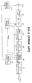
- Figure 7 is a block diagram showing another embodiment of the character signal display for a camcorder.
- the composite video signal generated by camera portion 10 is selected by selector 31, and the synchronous signal is separated from the selected camera video signal. Then, a vertical synchronous signal is separated from the synchronous signal by micro-computer 60 so as to output to character signal generator 70.
- the horizontal and vertical synchronous signal input of character signal generator 70 are connected to the horizontal and vertical synchronous oscillator within electronic view finder 80.
- the character display location is controlled by employing the horizontal and vertical synchronous signals generated by electronic view finder 80.
- the apparatus described may be adapted for use in any device incorporating a camcorder character display.
- the horizontal and/or vertical synchronous signals generated from a camera portion and view finder are utilized without using an additional synchronous signal separator and synchronous signal generator.
- the manufacturing cost can be cut down, and the character data can be exactly displayed onto the monitor and the view finder.
Landscapes
- Engineering & Computer Science (AREA)
- Multimedia (AREA)
- Signal Processing (AREA)
- Computer Graphics (AREA)
- Studio Circuits (AREA)
- Synchronizing For Television (AREA)
Applications Claiming Priority (4)
| Application Number | Priority Date | Filing Date | Title |
|---|---|---|---|
| KR93014810A KR970005713B1 (en) | 1992-07-31 | 1993-07-31 | Process for correcting warped surface of plastic encapsulated semiconductor device |
| KR1481093 | 1993-07-31 | ||
| KR2019940017905U KR0139947Y1 (ko) | 1993-07-31 | 1994-07-19 | 캠코더의 문자신호 표시장치 |
| KR1790594 | 1994-07-19 |
Publications (3)
| Publication Number | Publication Date |
|---|---|
| EP0637169A2 true EP0637169A2 (de) | 1995-02-01 |
| EP0637169A3 EP0637169A3 (de) | 1996-06-12 |
| EP0637169B1 EP0637169B1 (de) | 2000-03-15 |
Family
ID=26629815
Family Applications (1)
| Application Number | Title | Priority Date | Filing Date |
|---|---|---|---|
| EP94305576A Expired - Lifetime EP0637169B1 (de) | 1993-07-31 | 1994-07-28 | Zeichensignalanzeige für einen Camcorder |
Country Status (5)
| Country | Link |
|---|---|
| US (1) | US5502487A (de) |
| EP (1) | EP0637169B1 (de) |
| JP (1) | JPH07154693A (de) |
| KR (1) | KR0139947Y1 (de) |
| DE (1) | DE69423395T2 (de) |
Cited By (3)
| Publication number | Priority date | Publication date | Assignee | Title |
|---|---|---|---|---|
| EP0794664A3 (de) * | 1996-03-05 | 1999-02-24 | Sony Corporation | Videokamera mit Aufzeichung/Wiedergabe und Steuerung davon |
| US5956461A (en) * | 1995-10-31 | 1999-09-21 | Hitachi, Ltd. | Camcorder and controller |
| DE19643853C2 (de) * | 1995-10-31 | 2002-01-24 | Matsushita Electric Industrial Co Ltd | Vorrichtung zur Verarbeitung von Videosignalen |
Families Citing this family (6)
| Publication number | Priority date | Publication date | Assignee | Title |
|---|---|---|---|---|
| JP3392967B2 (ja) * | 1994-12-27 | 2003-03-31 | ペンタックス株式会社 | スチルビデオカメラ |
| JPH08223472A (ja) * | 1995-02-15 | 1996-08-30 | Techno Kapura:Kk | ビデオ信号の出力方法、画像処理用カメラおよびそれを用いた画像処理システム |
| WO1996028930A1 (en) * | 1995-03-10 | 1996-09-19 | Hitachi, Ltd. | Image pickup device and its signal processor |
| US6044198A (en) * | 1995-10-27 | 2000-03-28 | Matsushita Electric Industrial Co., Ltd. | Digital signal recording/reproducing device with editor |
| KR100873437B1 (ko) * | 2002-11-28 | 2008-12-11 | 삼성전자주식회사 | Pip화면을 이용한 듀얼모드 신호처리장치 |
| JP2006047412A (ja) * | 2004-07-30 | 2006-02-16 | Sanyo Electric Co Ltd | インターフェース装置及び同期調整方法 |
Family Cites Families (5)
| Publication number | Priority date | Publication date | Assignee | Title |
|---|---|---|---|---|
| US4325080A (en) * | 1979-04-24 | 1982-04-13 | Olympus Optical Co., Ltd. | Apparatus for displaying video track number in viewfinder of video camera |
| JPS6016777A (ja) * | 1983-07-08 | 1985-01-28 | Victor Co Of Japan Ltd | 文字信号発生装置 |
| JP2899023B2 (ja) * | 1989-09-28 | 1999-06-02 | キヤノン株式会社 | ビデオシステム |
| CA2061700C (en) * | 1991-02-20 | 1999-01-12 | Makoto Hasegawa | Video signal synthesizing system for synthesizing system's own signal and external signal |
| EP0547899A1 (de) * | 1991-12-18 | 1993-06-23 | Sony Corporation | Anzeige von abnormalen Zuständen einer Videokamera oder eines Videobandaufzeichnungsgerätes |
-
1994
- 1994-07-19 KR KR2019940017905U patent/KR0139947Y1/ko not_active Expired - Fee Related
- 1994-07-28 EP EP94305576A patent/EP0637169B1/de not_active Expired - Lifetime
- 1994-07-28 DE DE69423395T patent/DE69423395T2/de not_active Expired - Lifetime
- 1994-08-01 US US08/283,805 patent/US5502487A/en not_active Expired - Lifetime
- 1994-08-01 JP JP6180264A patent/JPH07154693A/ja active Pending
Cited By (5)
| Publication number | Priority date | Publication date | Assignee | Title |
|---|---|---|---|---|
| US5956461A (en) * | 1995-10-31 | 1999-09-21 | Hitachi, Ltd. | Camcorder and controller |
| DE19643888C2 (de) * | 1995-10-31 | 2001-02-08 | Hitachi Ltd | Integral mit einer Kamera und einer Zoomlinse versehener Videokassettenrekorder |
| DE19643853C2 (de) * | 1995-10-31 | 2002-01-24 | Matsushita Electric Industrial Co Ltd | Vorrichtung zur Verarbeitung von Videosignalen |
| EP0794664A3 (de) * | 1996-03-05 | 1999-02-24 | Sony Corporation | Videokamera mit Aufzeichung/Wiedergabe und Steuerung davon |
| US5949957A (en) * | 1996-03-05 | 1999-09-07 | Sony Corporation | Video camera having storage medium-equipped recorder-reproducer and control method thereof |
Also Published As
| Publication number | Publication date |
|---|---|
| KR950005059U (ko) | 1995-02-18 |
| DE69423395T2 (de) | 2000-07-27 |
| KR0139947Y1 (ko) | 1999-05-01 |
| JPH07154693A (ja) | 1995-06-16 |
| EP0637169B1 (de) | 2000-03-15 |
| EP0637169A3 (de) | 1996-06-12 |
| US5502487A (en) | 1996-03-26 |
| DE69423395D1 (de) | 2000-04-20 |
Similar Documents
| Publication | Publication Date | Title |
|---|---|---|
| EP0533092B1 (de) | Videokamera mit umschaltbarem Bildseitenverhältnis | |
| KR920004563B1 (ko) | 영상 재생 장치에 의해 유입된 전류를 변화시키는 장치 | |
| EP0637169B1 (de) | Zeichensignalanzeige für einen Camcorder | |
| US4774580A (en) | Video signal control apparatus | |
| JPH04271685A (ja) | 同期信号復元回路 | |
| JP2651012B2 (ja) | テレビジョン受像機 | |
| US20050068424A1 (en) | Image pickup apparatus and control unit therefor | |
| EP0218291B1 (de) | Fernsehkamera mit elektronischem Sucher | |
| JPH029512B2 (de) | ||
| KR100211797B1 (ko) | 비디오 신호 전환회로 및 방법 | |
| JP3683969B2 (ja) | マルチメディアテレビ受像装置 | |
| JPH06141252A (ja) | モニタ装置 | |
| JP2846870B2 (ja) | クランプ回路 | |
| JPH0748833B2 (ja) | 画像合成装置 | |
| JPH05274787A (ja) | 自動利得制御回路 | |
| US20020075410A1 (en) | On-screen display apparatus | |
| JPH0132449Y2 (de) | ||
| KR970004922Y1 (ko) | 세캄 컬러신호의 게이트 펄스 자동 조절회로 | |
| KR200156374Y1 (ko) | 비디오일체형 카메라의 온스크린표시(osd)용 수평.수직안정 기준신호 입력회로 | |
| JP2719466B2 (ja) | 撮像システム | |
| JPH0728773Y2 (ja) | ブラウン管のビームブランキング回路 | |
| KR19990074944A (ko) | 아날로그 비디오캠코더와 퍼스널컴퓨터간 인터페이싱을 위한장치 | |
| JPH1079951A (ja) | カメラ装置 | |
| JPH05308585A (ja) | 水平同期信号検出回路 | |
| JPH1042159A (ja) | テレビジョン受像機及び受像管の制御方法 |
Legal Events
| Date | Code | Title | Description |
|---|---|---|---|
| PUAI | Public reference made under article 153(3) epc to a published international application that has entered the european phase |
Free format text: ORIGINAL CODE: 0009012 |
|
| AK | Designated contracting states |
Kind code of ref document: A2 Designated state(s): DE FR GB |
|
| PUAL | Search report despatched |
Free format text: ORIGINAL CODE: 0009013 |
|
| AK | Designated contracting states |
Kind code of ref document: A3 Designated state(s): DK FR GB |
|
| 17P | Request for examination filed |
Effective date: 19961118 |
|
| 17Q | First examination report despatched |
Effective date: 19980709 |
|
| GRAG | Despatch of communication of intention to grant |
Free format text: ORIGINAL CODE: EPIDOS AGRA |
|
| RBV | Designated contracting states (corrected) |
Designated state(s): DE FR GB |
|
| GRAG | Despatch of communication of intention to grant |
Free format text: ORIGINAL CODE: EPIDOS AGRA |
|
| GRAH | Despatch of communication of intention to grant a patent |
Free format text: ORIGINAL CODE: EPIDOS IGRA |
|
| GRAH | Despatch of communication of intention to grant a patent |
Free format text: ORIGINAL CODE: EPIDOS IGRA |
|
| GRAA | (expected) grant |
Free format text: ORIGINAL CODE: 0009210 |
|
| AK | Designated contracting states |
Kind code of ref document: B1 Designated state(s): DE FR GB |
|
| REF | Corresponds to: |
Ref document number: 69423395 Country of ref document: DE Date of ref document: 20000420 |
|
| ET | Fr: translation filed | ||
| PLBE | No opposition filed within time limit |
Free format text: ORIGINAL CODE: 0009261 |
|
| STAA | Information on the status of an ep patent application or granted ep patent |
Free format text: STATUS: NO OPPOSITION FILED WITHIN TIME LIMIT |
|
| 26N | No opposition filed | ||
| REG | Reference to a national code |
Ref country code: GB Ref legal event code: IF02 |
|
| PGFP | Annual fee paid to national office [announced via postgrant information from national office to epo] |
Ref country code: DE Payment date: 20130702 Year of fee payment: 20 |
|
| PGFP | Annual fee paid to national office [announced via postgrant information from national office to epo] |
Ref country code: GB Payment date: 20130703 Year of fee payment: 20 Ref country code: FR Payment date: 20130726 Year of fee payment: 20 |
|
| REG | Reference to a national code |
Ref country code: DE Ref legal event code: R071 Ref document number: 69423395 Country of ref document: DE |
|
| REG | Reference to a national code |
Ref country code: GB Ref legal event code: PE20 Expiry date: 20140727 |
|
| PG25 | Lapsed in a contracting state [announced via postgrant information from national office to epo] |
Ref country code: DE Free format text: LAPSE BECAUSE OF EXPIRATION OF PROTECTION Effective date: 20140729 |
|
| PG25 | Lapsed in a contracting state [announced via postgrant information from national office to epo] |
Ref country code: GB Free format text: LAPSE BECAUSE OF EXPIRATION OF PROTECTION Effective date: 20140727 |